
Abstract
The aim of this work is to study the operation and performance characteristics of medium consistency pump in different conditions, and a sonar flowmeter and monitoring system are used in the experimental set up. The head, efficiency, gas fraction, and max flow rate were studied under different pulp concentrations 7.52%, 9.3%, and 12.1%; at speeds 960, 1140, and 1500 r/min; and degas vacuum degree. The dimensionless analysis is applied to pulp pumping. The experimental results show that pump head and efficiency decrease with the increase in the pulp concentration at constant flow rate. Vacuum degree has significant effect on pump performance. Medium consistency pump can pump pulp concentration at 7.52% without vacuum, but pump head and efficiency decrease obviously with the increase in the flow rate. With increase in vacuum degree, pump head increases and gas fraction decreases at pump outlet. Head increases with the increase in rotation speed. The higher rotation speed leads to the lower vacuum degree, which indicates that enhancing speed improves gas–liquid separation. With the increase in concentration of the gas fraction, the degas vacuum degree increases. The max flow rate decreases with the increase in concentration and increases with the increase in rotation speed.
Introduction
The papermaking industry used more low consistency centrifugal pump to transport low concentration pulp suspension (<7%) at present. Medium consistency (MC) technology was first developed in the Northern Europe in 1970s, and MC pump was one of the important equipments to pump the pulp slurries at 7%–20% mass concentration (Cm), which is useful to greatly reduce the number of pulp pump, simplify the entire pulping process, and reduce water consumption and wastewater discharge. 1 MC pump is becoming popular with papermaking process.
MC pulp suspension is a gas–liquid–solid three-phase non-Newtonian fluid and the physical characteristics are very complex2,3. It is hard to use the numerical calculation method for predicting MC pump performance. The effect of import bubble on the performance of a centrifugal pump is studied by Murakami and Minemura, 4 and it was found that the increase in gas will lead to decrease in the head. Gullichsen and Harkonen 5 and Kamyr in 1981 studied that one and split two structures of consistency pulp pump were experimentally tested to study the transport properties of the pulp density of 12% and water pump; the results showed that the accumulation of gas in the pump flow caused by a large performance is the reason for the decline. Pressure difference of pump suction hole and pulp pump is the main reason impacting gas–liquid separation, and the relationship between gas volume at pump inlet and gas–liquid separation is not obvious.
The flow models at different flow conditions were investigated, and the MC pump performance at different consistencies and vacuum was studied by S Cao and R Oba 6 in 1996. In 1998, Cao and Oba 7 experimentally tested the performance of MC pulp pump with a vacuum pump, and the result showed that the characteristic of MC pump performance is determined by vacuum degree, and vacuum pressure increases with the increase in pulp consistency. B Erickson, 8 in 2000, discussed the importance of MC pump designed by ITT in pulp transport system. Using MC pump had obvious effect on energy saving and reduction of water. In 2003, V Rejio 9 introduced the Sulzer production of pulp pump medium consistency equipment (MCE), which has high performance with pulp consistency at 14%–16% and at temperature 95°C, but the details of experimental test data were unpublished. Pulp and Paper Laboratory of South China University of Technology designed an MC pulp pump MCP in 2003, and experiment was studied. 10 In 2007, H Li et al. 11 established an MC pump test system, and the performance with consistency at 11% was tested. HF Zhuang, 12 in 2012, investigated the effects of different speeds and vacuum pressure on the consistency pulp performance, and the result showed that increase in the pump speed and the degree of vacuum can improve MC pump performance. In 2014, XD Ma13,14 analyzed the hydraulic structure of MC pump and built-in pump performance test platform to study the change in different pulp concentrations, the impeller exit width, and degree of vacuum in the operating characteristics of pump.
However, there is lack of relevant consistency pulp pump design theory. In order to obtain a reference theoretical guidance, the performance test of MC pump still needs further study. Therefore, this article will use the sonar flow measurement system to set up MC pump test platform. The rate of gas was obtained under different conditions of the pulp, and then the pump performance curve was studied. The effects of concentration, degree of vacuum, and speed on pump characteristic were revealed; this study provided guidance and reference for MC pump design theory and operation.
Experimental setup and test scheme
Structure of MC pump
The MC pump structure is shown in Figure 1. As compared with general centrifugal pump, a special device, turbulence generator with fluid consistency pulp, was installed in front of impeller. There was amount of gas in MC pulp. The gas was needed to be degased, or MC pump disabled transportation because of gas gathering in impeller and then clogging of the flow channel. The gas in pulp was first separated while pulp flows through turbulence generator and gathered in impeller inlet, and then gas flowed through the vent holes on impeller. With back of impeller blades separating, gas moved into the vacuum chamber, and last gas was degassed at suction hole. The parameters are shown in Table 1.
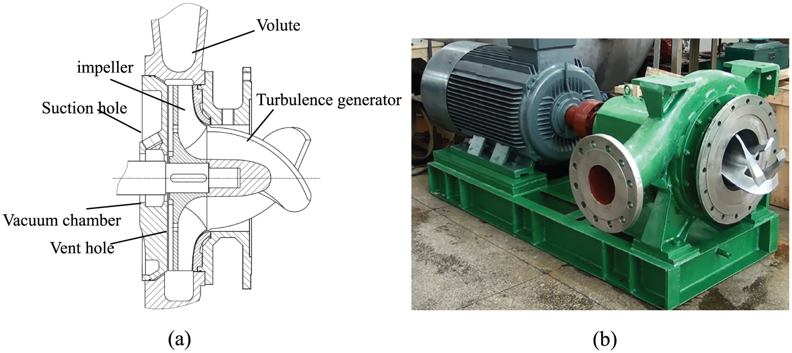
(a, b) Structure of medium consistency pulp pump.
Design parameters of MC pump.

Experimental setup layout
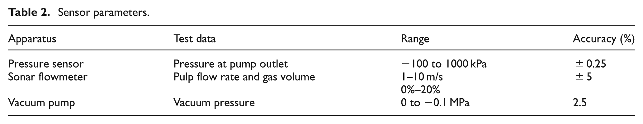
Due to the specialty of pulp, external performance of pulp pump is very different with general centrifugal pump, therefore a particular test system was designed in Figure 2. The experiment set up consists of a MC pump, a frequency conversion motor, a vacuum pump, a ball valve, a vacuum manometer, a pressure sensor, a sonar flowmeter, a slide valve, and a tank. The MC pump is driven by a four-pole induction motor, and the speed of induction motor is controlled by an inverter to realize different rotational speeds. The vacuum pressure is controlled by ball valve. The pulp flow rate is measured by sonar flowmeter. The pressure signal is acquired by pressure sensor. The parameters of sensor are shown in Table 2.

Schematic diagram of testing.
Sensor parameters.
The sonar flowmeter, SONARtrac®VF/GVF-100, consists of volume flow rate and gas volume fraction, as shown in Figure 3. As compared with a general electro-magnetic flowmeter, the sonar flowmeter does not have direct contact with pulp flow, hence the data are prevented from liner inside pipe, fouling impact. The sonar flowmeter is interposed to MC pump discharge piping; using sonar measurement principle, we can measure flow rate and gas rate directly, which has no pressure limit, no wear, and no signal attenuation characteristics.
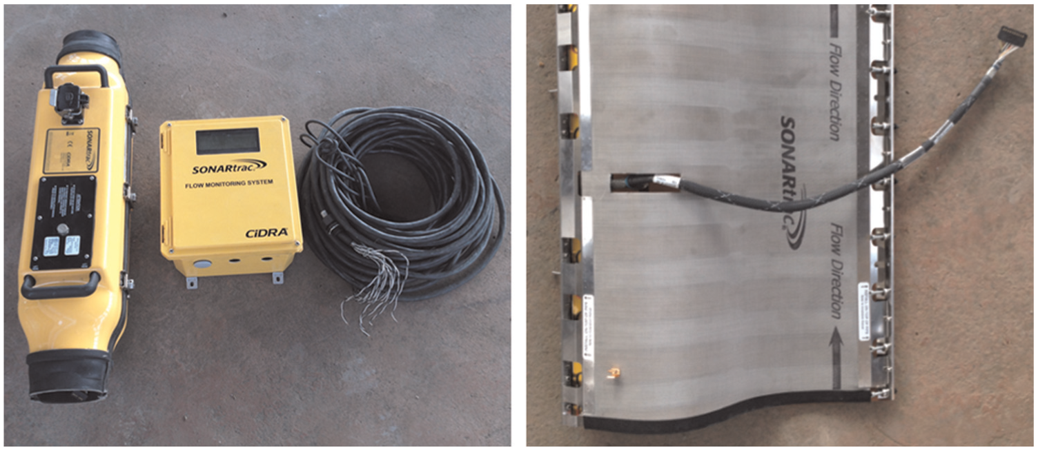
Sonar flowmeter.
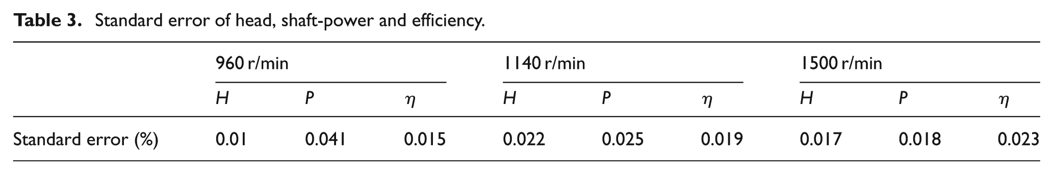
The standard errors of head, shaft-power, and efficiency at different rotational speed are shown in Table 3. The maximal standard errors of H, P, and η are 0.022, 0.041, and 0.023, respectively. However, the MC pulp is complex fluid, and the flow rate can only be measured by sonar flowmeter, hence the flow rate accuracy needs to improve.
Standard error of head, shaft-power and efficiency.
Test scheme
For studying the effects of consistency, vacuum pressure, and speed on performance of MC pump, kraft liner paper pulp at concentrations 7.52%, 9.3%, and 12.1% was used. The vacuum pressure was changed from −15 to −40 kPa. The vacuum pressure was adjusted at different concentrations, speed, and flow rate during experiment. The speeds 960, 140, and 1500 r/min were controlled by a frequency inverter. The head, efficiency, and gas volume fraction were investigated at different consistency pulp, speed, flow rate, and vacuum pressure. Three experimental data were recorded at every condition, and the mean value was calculated.
The forms of different concentration pulp are shown in Figure 4. The pulp acts as solid when the concentration is 12.1%, as shown in Figure 4(a). As water contains in the structure of fiber network, MC pulp does not have flow properties. With the decrease in the concentration, pulp slurry contains more water (see Figure 4(d)), hence it has a strong flow characteristics. The pulp physical properties are shown in Table 4.

The different consistency pulp: (a) Cm = 12.1%, (b) Cm = 9.3%, (c) Cm = 7.52%, and (d) Cm = 5.13%.
Pulp physical properties.

Figure 5 shows the relationship between the shear stress and shear rate. When the shear stress was in the turbulent regime, the shear stress increased linearly. The shear stress increased with shear rate and pulp consistency.
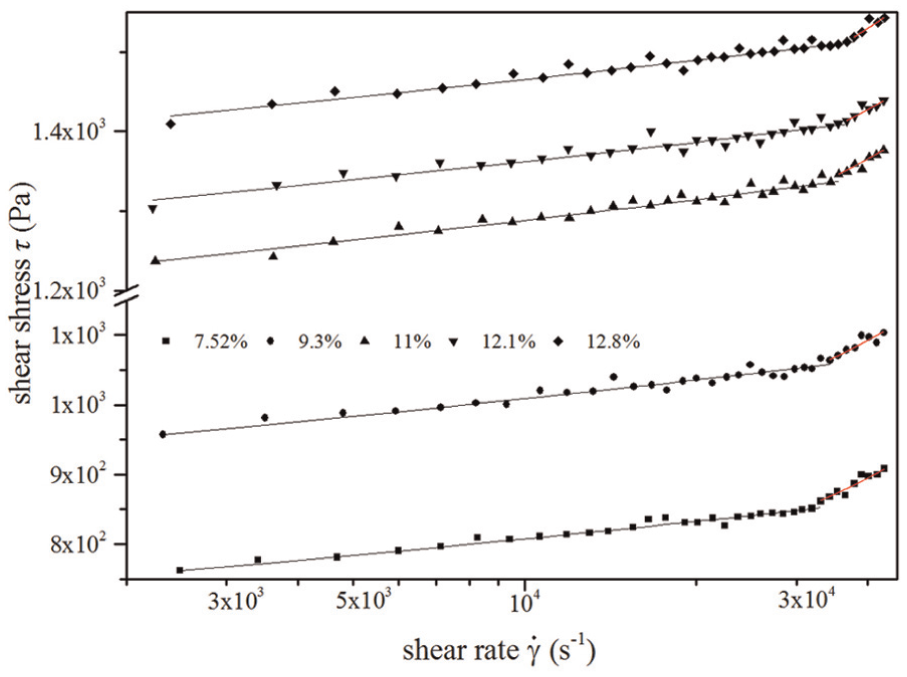
Shear stress versus shear rate of kraft liner paper pulp and several mass concentrations.
Experimental results
The performance curves of MC pump with pumping water are shown in Figure 6. The pump efficiency, η, can be expressed as

where ρ is the density of pulp, g is the gravity, Q is the flow rate, H is pump head, and P is the input power.
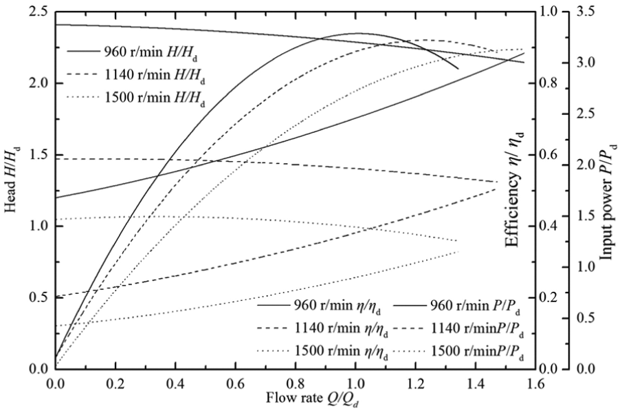
Performance curves with pumping water at different speeds.
The head curves decrease slightly with the increase in flow rate, and the maximum efficiency is about 60%. With increase in speed, head increases, and the maximum efficiency deviates to large flow.
Influence of pulp concentration
Figure 7 shows performance curves of different concentration pulp, and the performance comparison of MC pump at speed 960, 1140, and 1500 r/min is shown in Figure 7(a)–(c). In Figure 7, the vacuum pressure reaches critical pressure when a little pulp flows out. At pulp concentration 7.52%, MC pump head decreases slightly when compared with pumping water, but the head decreases obviously with the increase in concentration. The efficiency decreases with the decrease in concentration. At critical pressure, the gas fraction at pump outlet is <1%. With the increase in flow rate, the gas fraction of pulp at pump outlet increases.

Performance curves of different concentration pulp: (a) n = 960 r/min, (b) n = 1140 r/min, and (c) n = 1500 r/min.
Effect of vacuum pressure
The performance curves of MC pump at different vacuum pressures are shown in Figure 8. The pulp is discharged from vacuum pump at critical vacuum pressure, which results in a waste pulp. With the increase in vacuum pressure, the head increases and the gas fraction at MC pump outlet decreases. When flow rate is <100 m3/h flow rate, the head decreases slightly, and with the flow rate continued to increase, the gas volume increases, as a result, head decreases sharply. When the vacuum degree is −33 kPa, efficiency is higher than that at critical vacuum pressure, indicating that there is an optimal vacuum value. The MC pump can work without vacuum condition, but with the increase in flow rate, performance significantly deteriorates, and head and efficiency drop significantly. From Figure 8(b), as a result of no vacuum, large amount of gas blocks impeller passage when pulp concentration is at 12.1%, so MC pump quickly loses transmission capacity. With the increase in vacuum pressure, the maximum flow rate increases.

Performance curves of different vacuum pressure: (a) Cm = 7.52%, n = 960 r/min and (b) Cm = 12.1%, n = 1140 r/min.
Performance curves at different speeds
The performance characteristics at different speeds are shown in Figure 9, and concentration Cm at 9.3% and 12.1% is shown in Figure 9(a) and (b), respectively. With the increase in rotational speed, head increases and efficiency has no obvious change. As a result of increasing speed, centrifugal force increases, hence the gas in MC pulp is easily separated. Increasing rotational speed improves gas–liquid separation and rate of gas containing at pump outlet decreases as a result.

Performance curves at different speeds: (a) Cm = 9.3% and (b) Cm = 12.1%.
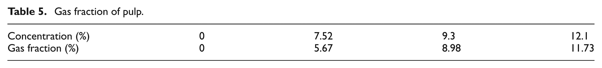
Without vacuum pump, the gas fraction is acquired by sonar flowmeter, as shown in Table 5. The gas fraction increases with the increase in pulp concentration, which coincide with the literature. 15
Gas fraction of pulp.
Head ratio and efficiency ratio
The dimensionless analysis is applied to experimental comparison. At the same flow rate, head ratio, RH, and efficiency ratio, RE, are expressed as follows

where Hs and Es are head and efficiency of pumping pulp, and HW and EW are head and efficiency of pumping water. At a flow rate 300, 450, and 500 m3/h and different concentrations, RH–n curves are shown in Figure 10. The RH tends to 1, which indicates that pumping at 7.52% pulp compared with water head has no significance on decreasing trend. The RH rises at flow rate 300 m3/h and speed 1140 r/min as a result of pulp fiber reducing flow loss. With the increase in rotational speed, RH increases at pulp concentration 9.3%, but RH decreases when the concentration is at 12.1%. At flow rate 450 m3/h and 500 m3/h conditions, increasing of pumping difficult increases with Pulp concentration, which makes the head ratio falling.

Head ratio at different flow rates: (a) Q = 300 m3/h, (b) Q = 450 m3/h, and (c) Q = 500 m3/h.
Figure 11 shows that the efficiency ratio, RE, changes with rotational speed at different flow rates and pulp concentrations. All RE is <1, which shows that pumping pulp decreases when compared with water efficiency, and the efficiency ratio decreases with the increase in pulp concentration. At flow rate 300 m3/h, the RE of pulp concentration 7.52% decreases with the increase in speed, as shown in Figure 11(a). At flow rates 450 and 500 m3/h and concentration 9.3%, the efficiency ratio decreased with the increase in speed. When pulp concentration is up to 12.1%, the efficiency ratio decreases first and then increases with the increase in speed.

Efficiency ratio at different flow rates: (a) Q = 300 m3/h, (b) Q = 450 m3/h, and (c) Q = 500 m3/h.
Effects of speed on vacuum pressure and gas fraction
The vacuum pressure and gas fraction are shown in Figure 12 at rotational speed 960, 1140, and 1500 r/min. The concentrations used in Figure 12(a) and (b) are 7.52%, 9.3% and 12.1%. The vacuum pressure and gas fraction increase with the increase in flow rate, and the gas fraction is <1%. At the same pulp concentration, vacuum pressure decreases with the increase in rotational speed, which indicates that increasing rotational speed can improve gas–liquid separation and reduce the suction vacuum pressure.

Vacuum pressure and gas fraction at different speeds: (a) Cm = 7.52%, (b) Cm = 9.3%, and (c) Cm = 12.1%.
Vacuum pressure at different concentrations and rotational speed
During experiment, the vacuum pressure degree is adjusted according to the flow rate for guaranteeing the normal operation of MC pump, and the parameters are shown in Table 6. At the same speed, vacuum pressure increases with the increase in pulp concentration. Vacuum pressure decreases with the decrease in speed.
Vacuum pressure at different concentrations and rotational speed.

Max flow rate
Figure 13 shows MC pump performance without vacuum pump, and the maximum flow rate at concentrations 9.3% and 12.1% is shown in Table 7. Without vacuum pump, the head of MC pump decreases with the increase in flow rate. The MC pump works normally without vacuum pump when the pulp concentration is at 7.52%. With the increase in pulp consistency, the gas in MC pulp increases and the gas blocks impeller channel, hence MC pump stops working, as shown in Figure 13(b) and (c). The maximum flow rate decreases with the increase in pulp concentration, but it increases with the increase in rotational speed, as shown in Table 7.

Max flow rate without vacuum pump: (a) Cm = 7.52%, (b) Cm = 9.3%, and (c) Cm = 12.1%.
Max flow rate without vacuum pump.

Conclusion
In this article, experimental set up of an MC pump is built. The operation performance is studied under different conditions. The head, efficiency, gas fraction, and max flow rate are investigated at different pulp concentrations, vacuum pressure, and rotational speeds. With the increase in concentration, the head and efficiency decrease obviously. With the increase in flow rate, the gas fraction of pulp at pump outlet increases. When the vacuum is −33 kPa, efficiency is higher than that at critical vacuum pressure, indicating there is an optimal vacuum value.
In conclusion, it is sensible to mention that MC pump can work without vacuum condition, but with the increase in flow rate, performance significantly deteriorates, and head and efficiency drop significantly. With the increase in rotational speed, head increases and efficiency has no obvious change. As a result of increase in speed, centrifugal force increases, so the gas in MC pulp is more easily separated. Increasing rotational speed improves gas–liquid separation. The maximum flow rate decreases with the increase in pulp concentration, hence rotational speed increases.
Footnotes
Appendix 1
Academic Editor: Ramoshweu Lebelo
Declaration of conflicting interests
The author(s) declared no potential conflicts of interest with respect to the research, authorship, and/or publication of this article.
Funding
The author(s) disclosed receipt of the following financial support for the research, authorship, and/or publication of this article: The support of Sichuan province department of education (Grant No. 17ZA0363), the Key Project of Xihua University (Grant No. Z1620408), Open Fund of Key Laboratory of Fluid and Power Machinery, Ministry of Education, Xihua University (Grant No. szjj2016-001) and National Natural Science Foundation of China (Grant No 51379179) is gratefully acknowledged. Thanks to my professor, Li Hong, and our research group for helping me.