
Abstract
Deep sea oil resources worldwide possess great potential for exploration; however, multiphase medium technology requires urgent development. The multiphase pump has achieved great success as one of the most advanced machinery in underwater oil and gas exploration. Tip clearance is inevitable between the rotating and stationary components of the multiphase pump. In this study, tip clearance sizes of 0.0, 0.2, 0.5, and 0.8 mm are selected to investigate the effect of tip clearance on energy performance and flow characteristics of a multiphase pump. Results show that pressure rises decrease by 10.72%, 24.96%, and 41.39% with gas volume fraction = 0% under different tip clearance sizes, while the pressure rises decrease by 17.10%, 25.35%, and 38.11% with gas volume fraction = 10%. The dominant frequencies and maximum amplitudes of pressure fluctuation rise with the increase in tip clearance. The entrainment effect between the tip leakage flow and main flow in the impeller strengthens with the increase in tip clearance size; the induced vortex area and leakage flow rate also increase.
Introduction
With rapid economic and industrial development, unprecedented changes have been brought to human life. Increasing production efficiency and reducing environmental pollution in energy development have become important issues. Countries urgently need to explore offshore oil resources because oil reserves have a huge impact on oil supply, which has become a major research focus for oil production. However, oil, seawater, and natural gas coexist at various stages of crude oil production, which imposes requirements on the transport performance of the pump. The oil–gas multiphase system with the multiphase pump as the core is a new technology for the transportation of crude oil on sea and land. In comparison with the traditional single-phase transportation of oil and gas, the multiphase pump has a simple structure that is easy to operate, saves investment costs, and improves exploration efficiency for oil fields. The technology has achieved great economic benefits in the development of underwater and offshore oil fields and received extensive attention in the field of oil and gas exploration at home and abroad. 1 Multiphase pumps can efficiently separate oil and natural gas, which is important in the production of oil and natural gas in the petroleum industry. However, the multiphase flow has different gas volume fractions (GVFs), which lead to a considerable decline in the efficiency and head of the multiphase pump. 2 Moreover, the torque of the multiphase pump greatly fluctuates, and the operation is extremely unstable, which results in mechanical failure in severe cases.
A certain gap is necessary between the blade and the shroud of the multiphase pump to ensure the relative movement between the impeller and the shroud. This gap is called tip clearance. Part of the fluid passes through the tip clearance under the pressure difference of the pressure and suction sides and leads to the tip leakage vortex with energy loss. The tip leakage vortex is an important source of unstable flow inside the pump, causing hydraulic friction loss inside the impeller, which results in the decline of energy performance. Inducing cavitation, vibration noise, and cavitation damage, which seriously affects safe pump operation, is easy.3,4 In addition, the impeller is susceptible to factors, such as machining distortion and working wear, which cause the change in tip clearance size, resulting in complicated tip leakage flow. Therefore, studying the influence of tip clearance on hydraulic performance and internal flow characteristics is of great scientific and engineering value.
Experimental observation based on high-speed photography and particle image velocimetry (PIV) technology is an important method for studying tip leakage flow. High-speed photography has achieved good results in capturing tip clearance vortex.5,6 It is used to study the leakage flow structure and transient evolution at the tip region 7 and measure the turbulent flow characteristics of the flow field. The flow mechanism and energy characteristics of a pump are consequently explored, 8 which show that tip leakage flow is formed when water passes through the tip clearance under the action of pressure difference and is mixed with the mainstream. High-speed photography can also provide detailed data on the instantaneous change in tip clearance flow and evolution of tip leakage vortex. 9 Observations based on a series of high-resolution images of PIV are obtained, and results show that the transient structure of the tip leakage vortex in the tip clearance is composed of small unsteady vortices. 10 Gas distribution and flow characteristics are also observed with the application of PIV. 11 Furthermore, exploration and analysis of the interaction between the tip clearance leakage flow and the passage swirling are conducted, and results reveal the influence of tip leakage flow on the secondary flow. In addition, other technologies have been applied in the study of tip clearance. Three-dimensional digital PIV 12 is used to measure the flow characteristics of the tip leakage flow and compare the measurements at different flow rates. Results display the average position of the tip leakage vortex and the instability of flow pattern. Laser Doppler velocimetry 13 is also used to conduct experimental analysis and shows that three vortex structures are formed near the tip. The tip clearance vortex plays a dominant role in the flow field, the separation vortex at the leading edge develops along the blade suction side and disappears in the rear region of the passage, and the swirling strength of tip leakage vortex is relatively weak.
Although the internal structure and development process of tip leakage flow can be observed via experimental techniques, the cost is high and the equipment inside the impeller is difficult to install. Therefore, many scholars have conducted numerical simulations of unsteady flow. In comparison with traditional experimental methods, a numerical simulation of multiphase flow has the advantages of low cost and repeatability, and it can predict the details of the flow field that are difficult to measure in experiments. The multiphase flow simulation employs the Euler–Lagrange14–16 and Euler–Euler methods,17–19 and can match well with advanced turbulence models such as large eddy simulation.20–22 Calculations using the Euler–Euler method is not limited by the GVF, and the computational resource cost is relatively low. 23 Interphase forces in the multiphase flow include drag, turbulent dispersion, virtual mass, and lift forces; 24 thus, simulation using the Euler–Euler method can reproduce the flow characteristics of a multiphase flow. 25 Research reveals that hydraulic resistance greatly influences the characteristics of multiphase flow, and the simulation result with the Euler–Euler method is more precise than that with the Euler–Lagrange method. 26 Therefore, the virtual mass force and resistance should also be considered to simulate fluctuation cycle accurately. 27
Numerical research on the effect of tip clearance on pressure fluctuation 28 has compared the dominant frequency and maximum fluctuation amplitude under different tip clearance sizes. Results show that the increase in tip clearance remarkably exacerbates pump performance degradation. Meanwhile, research on energy performance29,30 reports that the effects of the impeller inlet and the flow passage on the pressure fluctuation are limited within a certain tip clearance. To verify this problem, a study on the effect of tip clearance on pressure fluctuation 31 has been conducted. Results show that the presence of tip clearances amplifies the dominant frequency of pressure fluctuation in the impeller region, whereas the influence of the diffuser on the pressure fluctuation is not evident. Numerical results have also revealed how tip leakage flow interferes with the mainstream because tip clearance changes, 32 as well as the special flow patterns, under designed and non-designed conditions. 33 The detailed flow field and streamline distribution in numerical simulation also find that the tip leakage flow will replace the wake and results in a strong leakage backflow; 34 thus, the wall boundary layer is thickened and forms the passage vortex. The presence of tip clearance also affects the radial force, 35 which decreases with the increase in tip clearance size. Numerical studies on the influence of tip clearance on tip leakage vortex 36 show that the strength of the leakage vortex increases with the tip clearance size; the primary and secondary leakage vortices are also strengthened. The development and the trajectory of leakage vortex along the blade suction surface show a regular trend.
Interaction among the tip leakage flow, the separation flow, and the mainstream forms a complicated leakage flow structure due to the large angle between the blades of the multiphase pump and the complex structure of the tip clearance region. A systematic study on the evolution mechanism of tip leakage flow under different tip clearance sizes and GVFs for the multiphase pump is still lacking. Thus, the numerical research on the unsteady flow in the multiphase pump is investigated to reveal the characteristics of tip leakage flow.
Physical model and computational mesh
Physical model of multiphase pump
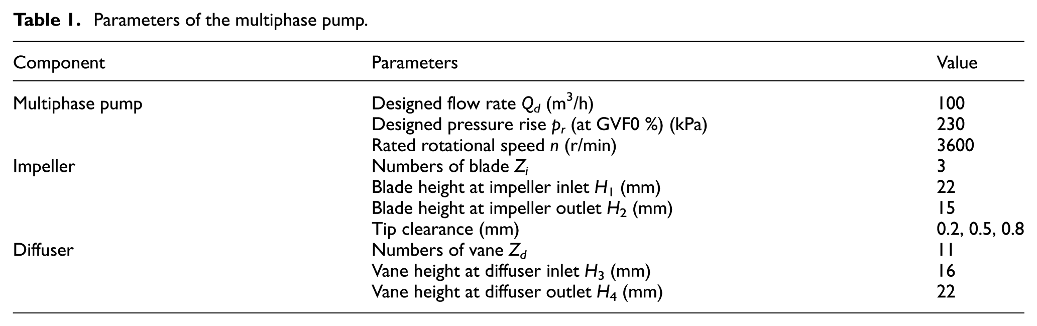
The model pump designed by Kim et al. 37 is selected for the present numerical work, with a designed flow rate of 100 m3/h, pressure rise of 230 kPa, and rotational speed of 3600 rpm. The impeller of the model pump consists of three blades, and the diffuser comprises 11 vanes. The multiphase pump includes an inlet pipe section, diffuser, impeller, and outlet pipe section. Table 1 lists the relative parameters. Figure 1 shows the computational domain of the multiphase pump.
Parameters of the multiphase pump.
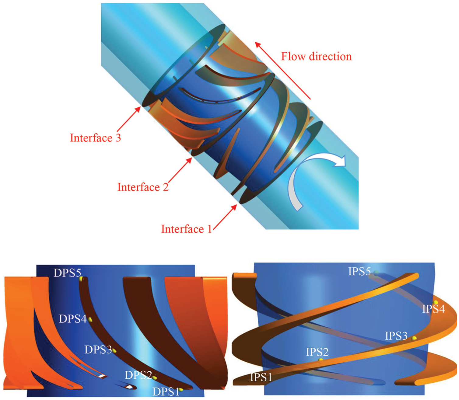
Computation domain of the multiphase pump and monitor points.
Computational mesh of multiphase pump
In comparison with the computational domain of the pump, the scale of tip clearance is small. The mesh must be refined to capture the structure of the tip leakage flow accurately. ICEM 17.0 and TurboGrid 17.0 are employed for mesh generation. The structural mesh with hexahedral block is selected for the computational domain considering that the structural mesh has fast generation speed and high quality.38,39 Ensuring equalization of adjacent mesh size is important to improve the convergence and accuracy of the numerical calculation. Figure 2 shows the mesh details of the impeller and tip clearance, which is facilitated to capture complex flow characteristics in the tip clearance region. Figure 2(a) shows the mesh of the hub and blade, and Figure 2(b) is a schematic view of the 0.5 mm tip clearance.

Mesh of impeller and tip clearance region: (a) impeller blade and (b) tip clearance region.
Numerical method and setting
Numerical method
Numerical simulations for steady and transient flow of the multiphase pump are performed using the computational fluid dynamics software CFX 17.0. The liquid is considered to be at a continuous phase, and the gas is considered to be at a dispersed phase composed of spherical bubbles with 0.1 mm diameter, which can be referred to the experiment results. 40 The calculation process does not consider the crushing and coalescence of bubbles, and the mass transfer between phases is not processed in the calculation. The turbulence model of the shear stress transport (SST), which combines the modeling characteristics of the standard k–ε and k–ω models, is selected. The k–ω model is used to calculate the near wall region, whereas the standard k–ε model is employed for the mainstream region. 41 Therefore, the SST model can present not only accurate prediction of the flow characteristics but also a certain applicability on the motion trajectory of the tip leakage vortex.
The inlet boundary condition is set as the static pressure inlet with specified GVF, while GVF is the percentage of gas in total gas–liquid volume, and the outlet of the pump is set as the mass flow under the guidance of experimental measurements, whereas the wall of the multiphase pump is considered to be the non-slip wall. The frozen rotor and transient rotor–stator methods are required for the steady and transient simulation to achieve coupling of the rotational impeller and the stationary diffuser, respectively. Unsteady simulations are performed when the steady calculations can be considered as convergence, which indicate that the value of the root mean square is below 10−5.
Independence test of mesh density
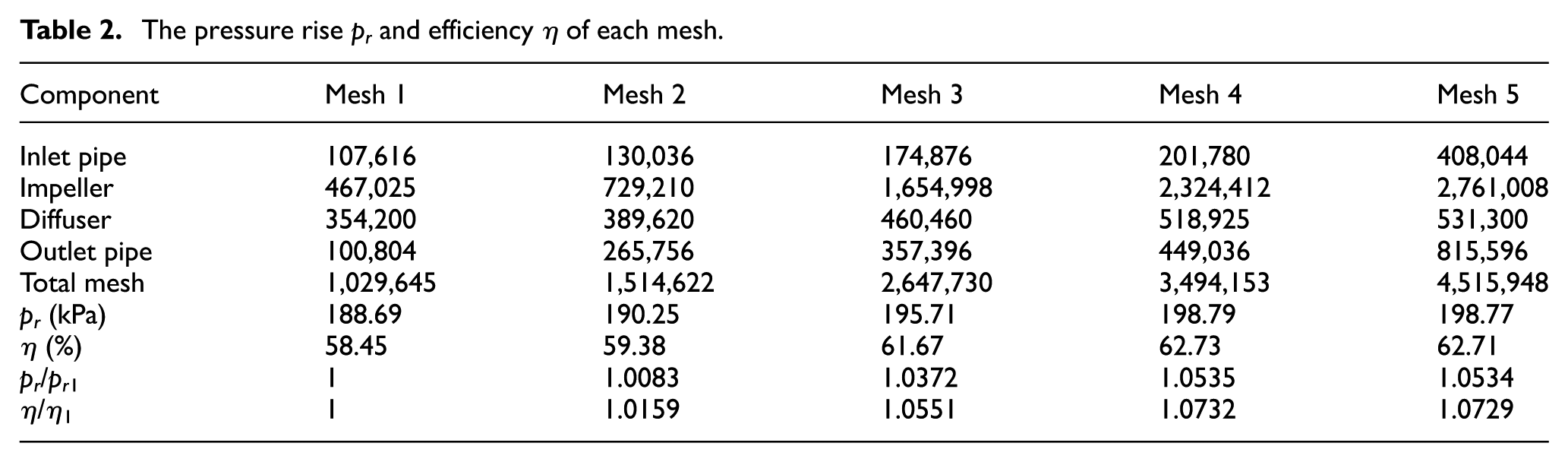
The mesh is an important factor in determining the accuracy of numerical calculations. The mesh independence test is conducted for the impeller with a tip clearance of 0.5 mm and other components to avoid the influence of the mesh on calculation results. Five sets of mesh independence analysis are performed under the designed condition. Table 2 displays the mesh details of each computational domain. Pressure rise pr is the difference between the pressure at the outlet and inlet of the multiphase pump, whereas efficiency η is the ratio between the actual and theoretical heads. The variation of pr and η between meshes 4 and 5 is minimal at 1%; thus, mesh 4 with 3,494,153 elements is used in the calculation to save computing time and resources.
The pressure rise pr and efficiency η of each mesh.
Independence test of time step
The impeller rotation time is Ti = 60/3600 = 0.0167 s; thus, the time steps of 1.7361 × 10⁻⁴, 8.6806 × 10⁻⁵, and 4.3403 × 10⁻⁵ s, corresponding with 96, 192, and 384 time steps for each revolution, are selected to evaluate time step independence.42,43 Figure 3 shows the pressure fluctuations on DPM3, DPM4, and DPM5, which are located in the flow passage of the diffuser. The discrepancy among these monitoring points is small, which indicates that the time step of 8.6806 × 10⁻⁵ s is suitable for the numerical simulations.

Independence test of time step.
Validation of numerical method
The comparison between experimental data and numerical results with the 0.5 mm tip clearance under GVF = 0% and GVF = 10% is conducted to validate the simulation. The experimental data can be obtained with a series of devices to measure pressure, flow rates, and torque. Figure 4 presents the variation of pressure rise and pump efficiency with the 0.5 mm tip clearance under GVF = 0% and GVF = 10%. The obtained results are compared with the experimental results, and the maximum error is within 7%, which indicates the accuracy and high reliability of numerical calculations because the results are consistent with experimental data curves.

Comparison of pump performance between experimental and numerical results: (a) GVF = 0% and (b) GVF = 10%.
Result and discussion
Energy performance
As shown in Figure 4, the difference between the efficiency and pressure rise under large flow conditions (1.1 – 1.2 Qd) is greater than that under small flow conditions (0.6 – 0.9 Qd). This result is due to the energy loss caused by the strengthened tip leakage vortex under large flow conditions. The tip leakage vortex considerably reduces the function of the impeller and causes large hydraulic loss. Consequently, the performance of the multiphase pump is drastically reduced.
As the tip clearance under the designed condition increases, the pressure rises and the efficiency of the multiphase pump gradually decreases, as shown in Table 3. This result is due to the increase in tip clearance size and leakage flow, resulting in serious hydraulic loss and decrease in overall energy characteristics. Meanwhile, the influence area by the tip leakage vortex is enlarged, and the pressure rise of the blade is remarkably reduced for tip leakage flow interference with the mainstream.
Energy performance of the pump with different tip clearance sizes.

The comparison of the pressure rise of the multiphase pump without tip clearance and GVF = 0% under the designed flow rate shows that the pressure rises decrease by 10.72%, 24.96%, and 41.39% for the pump with a tip clearance of 0.2, 0.5, and 0.8 mm, respectively. In comparison with the pressure rise without tip clearance and GVF = 10% under the designed flow rate, the pressure rises decrease by 17.10%, 25.35%, and 38.11% with a tip clearance of 0.2, 0.5, and 0.8 mm, respectively. The results indicate that tip clearance has a considerable effect of the multiphase pump on the energy performance.
Pressure fluctuation
Interference of the tip leakage flow to the mainstream and the vortex and instability of the internal flow in the multiphase pump may occur due to the rotor–stator interaction between the impeller and the diffuser. Therefore, the steady simulation cannot accurately reflect the flow in the pump. To reveal the influence of the tip clearance on the transient flow characteristics in the multiphase pump, the pressure fluctuation of the impeller blade is monitored based on the steady results, and the dominant frequency analysis is conducted. To improve the resolution of fast Fourier transform analysis and minimize spectral leakage, five impeller cycles are calculated to make the pump as stable as possible, and 10 cycles are then selected as sampling time.
Figure 5 shows the frequency spectra of pressure fluctuation on IPS1–IPS5 with different tip clearance sizes under GVF = 0% and GVF = 10% at the designed flow rate. The pressure fluctuation amplitude from inlet to outlet gradually increases when the tip clearance is 0.0 and 0.2 mm because the impeller is a pressurized component, and it is attributed to the rotor–stator interaction between impeller and diffuser. 44 Meanwhile, the pressure fluctuation of IPS1–IPS2 is higher than other points when the tip clearance is 0.5 and 0.8 mm, because the tip leakage flow exacerbates the fluctuation characteristics of the near tip region. As the tip leakage flow extends to the mainstream, its fluctuation strength also transmits to the flow passage, thereby greatly affecting the fluctuation characteristics of the impeller inlet. This occurrence also indicates that the tip clearance considerably influences pressure fluctuation, which is consistent with previous studies; thus, the tip clearance is not the main reason for the periodic pressure fluctuation at the impeller inlet, although it will aggravate the fluctuation characteristics of the near wall region.
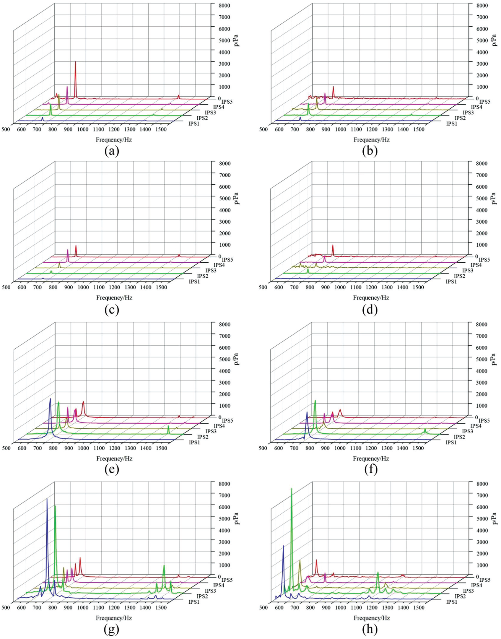
Frequency spectra of pressure fluctuation on IPS1–IPS5 with different tip clearance sizes under GVF = 0% and GVF = 10%: (a) GVF = 0%, Tip = 0.0 mm; (b) GVF = 10%, Tip = 0.0 mm; (c) GVF = 0%, Tip = 0.2 mm; (d) GVF = 10%, Tip = 0.2 mm; (e) GVF = 0%, Tip = 0.5 mm; (f) GVF = 10%, Tip = 0.5 mm; (g) GVF = 0%, Tip = 0.8 mm; and (h) GVF = 10%, Tip = 0.8 mm.
The dominant frequency of the impeller is 660 Hz when the tip clearance is 0.0 and 0.2 mm, which is related to the number of vanes. Other dominant frequencies exist when the tip clearance is 0.5 and 0.8 mm. For example, the dominant frequency of the impeller is 707.63 and 689.64 Hz for tip clearance of 0.5 and 0.8 mm, respectively. This phenomenon can be attributed to the tip leakage vortex induced by the tip clearance. The dominant frequency of the pressure fluctuation in the pressure side is remarkably different with the change in tip clearance, which results in a higher dominant frequency.
Figure 6 shows the amplitude of pressure fluctuation on IPS1–IPS5 with different tip clearance sizes.
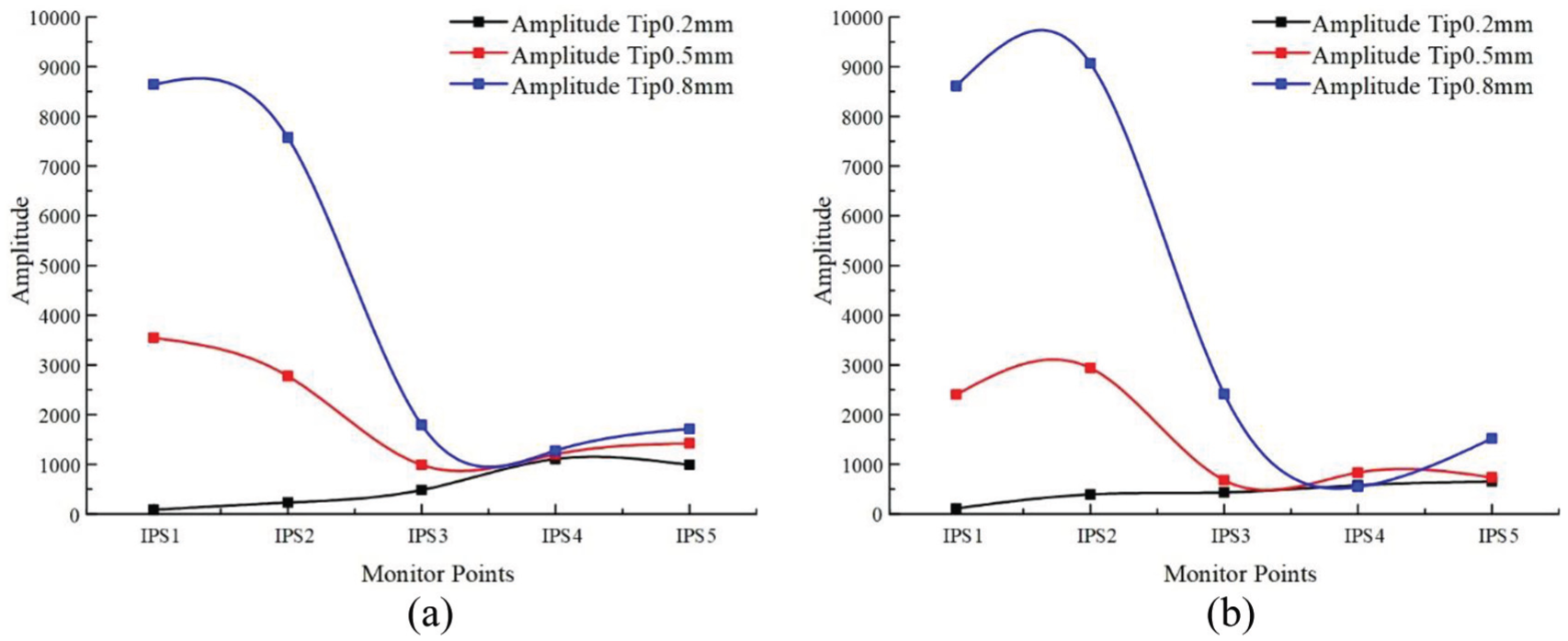
Amplitude of pressure fluctuation on IPS1–IPS5 with different tip clearance sizes: (a) GVF = 0% and (b) GVF = 10%.
For the dominant frequency under GVF = 0% and GVF = 10%, the amplitude generally increases with the tip clearance size. When the tip clearance changes from 0.2 to 0.8 mm under GVF = 0%, the amplitude of IPS1 changes from 83.14 to 8641.14 Pa. When the tip clearance size increases from 0.2 to 0.8 mm under GVF = 10%, the amplitude of the IPS1 gradually increases from 112.28 to 4611.73 Pa. The amplitude changes with the increase in tip clearance size because of the influence of the tip leakage flow. The amplitude of IPS3 and IPS4 is relatively small in the middle of the impeller, which can be attributed to the sufficient mixing of gas and liquid, thereby resulting in uniform flow pattern at this position. For the IPS5 at the impeller outlet, the amplitude slightly increases due to the rotor–stator interaction between the impeller and the diffuser. For GVF = 0%, the average fluctuation amplitude with tip clearance of 0.2 and 0.5 mm is lower than that with tip clearance of 0.8 mm by 86.22% and 52.68%, respectively. Meanwhile, for GVF = 10%, the average fluctuation amplitude with tip clearance of 0.2 and 0.5 mm is lower than that with tip clearance of 0.8 mm by 85.82% and 58.20%, respectively. The tip clearance plays a more important role in affecting the fluctuation amplitude than GVF.
Cross-sections are set with a distance of 0.01 mm from the blade tip and are used in the following figures. Figure 7 shows the pressure distribution of the sections under GVF = 0% and GVF = 10%. Pressure is generally the highest when tip clearance does not exist, and the pressure distribution is relatively regular from the inlet to the outlet. A narrow high-pressure zone exists at the leading edge due to the flow impact, which results in high-pressure fluctuation in Figures 5 and 6. Nevertheless, the overall pressure transition is stable, and the pressure in the pressure side is higher than the suction side at the corresponding position. The trend of pressure distribution under GVF = 0% and GVF = 10% is basically similar. A significant low-pressure zone caused by the leakage flow on the suction side with tip clearance emerges. The tip leakage flow becomes strong, and the range of the low-pressure zone becomes large with the increase in tip clearance size. The mixing between the tip leakage flow and the mainstream causes an extremely disordered distribution of pressure in the tip region, which indicates that the tip clearance size increases the operating instability of the multiphase pump.
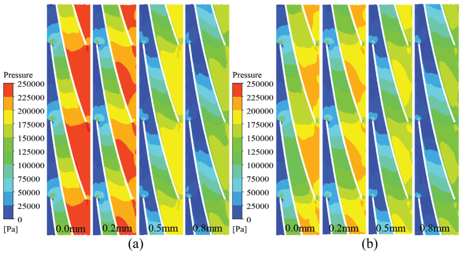
Pressure distribution in near tip region with different tip clearance sizes under (a) GVF = 0% and (b) GVF = 10%.
GVFs
Figure 8 shows the GVF distribution with different tip clearance sizes. The GVF near the shroud is lower than that near the hub in the impeller, because the density of water is larger than that of gas. Thus, the centrifugal force pushes the water to accumulate near the shroud. 45

GVF distribution in impeller with different tip clearance sizes under GVF = 10%.
Gas mainly accumulates on the suction side due to the influence of the pressure gradient. When a tip clearance in the impeller exists, the leakage flow passes through the tip clearance to the suction side. Consequently, the vortex is formed, because the tip leakage flow is concentrated in the suction side with gas, which results in a higher GVF in the suction side of the blade. The liquid flows along the blade carrying the gas with the increase in the tip clearance size and leakage flow. Therefore, GVF becomes high in the middle and rear regions of the impeller with tip clearance of 0.5 and 0.8 mm, respectively.
Vortex and velocity swirling strength
Figure 9 displays the Q vortex structure at the leading edge of the blade with four tip clearance sizes under GVF = 0% and GVF = 10%, and the vortex is strengthened with the increase in GVF. The vortex is represented by the Q criterion, which is the second invariant of the velocity gradient tensor defined as

Vortex structure at leading edge of the blade: (a) 0.0 mm under GVF = 0%, (b) 0.2 mm under GVF = 0%, (c) 0.5 mm under GVF = 0%, (d) 0.8 mm under GVF = 0%, (e) 0.0 mm under GVF = 10%, (f) 0.2 mm under GVF = 10%, (g) 0.5 mm under GVF = 10%, and (h) 0.8 mm under GVF = 10%.
The vortex only occurs, develops, and disappears in the tip region. The vortex distribution area is small with tip clearance of 0.2 mm, because the velocity of the tip leakage flow is small and the energy is almost exhausted when the leakage flow reaches the suction side of the blade. Furthermore, the leakage flow partially flows into the next flow passage as the impeller rotates, which affect the flow field of the passage. Different degrees of vortices occur at the leading edge of the blade, which cause the fluctuation amplitude on IPS1 and IPS2 to be greater than other points. The eddy energy consumption enlarges as the influence area of the tip leakage vortex gradually increases. As a result, the leakage vortex interferes with the mainstream, which greatly affects the performance of the pump.
Figure 10 shows the streamline diagram of the tip clearance area under GVF = 10% located at a section, which is selected downstream from the leading edge with an axial rotation angle of 90°. The figure shows a significant difference in the position and influence range of the tip leakage vortex. Without tip clearance, the streamline is smooth without tip leakage vortex. Primary and secondary leakage vortex structures are formed in the suction surface with tip clearance of 0.2 mm, and the GVF in this location is relatively high. When tip clearance is 0.5 mm, the leakage vortex structure assumes a band shape with an enlarged influencing area. No significant secondary leakage vortex appears because the gas in the suction side is inadequate for blocking the leaking fluid. When the tip clearance size increases to 0.8 mm, the leakage vortex structure assumes a circle shape and the area is evidently larger than the others.

Streamline distribution under GVF = 10%: (a) 0.0 mm, (b) 0.2 mm, (c) 0.5 mm, and (d) 0.8 mm.
Figure 11 shows the streamline and velocity swirling strength at different tip clearance sizes under the designed condition. S1 is the axial section at the blade leading edge. S2 is the axial section downstream from the leading edge with an axial rotation angle of 30°, and S3 is the axial section downstream from the leading edge with an axial rotation angle of 60°. As shown in the distribution of the streamline, the tip leakage flow is relatively small with tip clearance of 0.2 mm, the leakage flow does not develop in the middle of the blade under the restriction of the mainstream, and the flow direction is consistent with the mainstream. The streamline of the leakage vortex spreads to the pressure side of the adjacent blade to a large extent when the tip clearance is 0.8 mm.

Streamline and velocity swirling strength in impeller near tip region under GVF = 10%: (a) 0.2 mm, (b) 0.5 mm, and (c) 0.8 mm.
The presence of tip clearance is related to the energy loss of the multiphase pump, and the tip leakage vortex plays a significant role. When the tip clearance is 0.2 mm, the flow loss caused by the tip leakage is small and the disturbance to the mainstream of the flow passage is not evident. With tip clearance of 0.5 mm, a significant leakage vortex is formed and the tip leakage vortex interacts with the mainstream, thereby resulting in the interference to the flow pattern in the impeller. When the tip clearance size increases to 0.8 mm, a large vortex is consequently formed near the tip region. A vital entrainment effect occurs between the tip leakage flow and the mainstream and further causes energy loss.
Velocity distribution
Figure 12 shows the velocity distribution in the middle section of the impeller. It exhibits a relatively regular layered distribution when tip clearance does not exist and gradually increases in the radial direction. A relatively stable high-speed zone is formed due to the flow near the pressure side. The velocity distribution at the near tip region is slightly disordered, and the area of high- or low-speed region gradually enlarges as the tip clearance size increases. This phenomenon is caused by the leakage flow being mixed with the mainstream, and a significant entrainment effect occurs, thereby resulting in the expansion of the vortex region to the mainstream region within the flow passage. For tip clearance of 0.2, 0.5, and 0.8 mm, the tip leakage flow rates are 0.01552, 0.03199, and 0.04825 kg/s, respectively. As the impeller rotates periodically, these complex vortices alternate with the mainstream and propagate along the impeller passage, thereby exacerbating flow instability and pressure fluctuation.

Velocity distribution in impeller with different tip clearance sizes under GVF = 10%: (a) 0.0 mm, (b) 0.2 mm, (c) 0.5 mm, and (d) 0.8 mm.
The velocity of the water flow is generally small due to the friction of the wall surface and the viscous force of the water flow at the hub. The axial velocity tends to increase slowly along the radial direction between the hub and the tip. The area of low-velocity region at the tip clearance size increases because of the influence of enlarging leakage vortex. The velocity shows a significant decrease with the increase in tip clearance size, and the high- and low-speed zones are gradually enlarged. Without tip clearance under the influence of wall frictional resistance and liquid viscous resistance, the absolute speed of the shroud is small. As the tip clearance gradually increases, the leakage flow in the tip region increases and the mixing effect between the tip leakage flow and the mainstream causes the expansion of the low-speed area. As a result, the clogging effect inside the impeller flow passage is induced, which causes vortex and flow instability; thus, the hydraulic performance of the pump gradually deteriorates.
Conclusion
The energy performance and flow characteristics of a multiphase pump are investigated in this study, and the conclusions can be drawn as follows.
The pressure rise and the efficiency of the multiphase pump decrease with the increase in tip clearance size.
The dominant frequencies of pressure fluctuations in pump are related to the blade and vane numbers. With the tip clearance size increasing from 0 to 0.8 mm, the dominant frequencies of pressure fluctuation transfer from 660 to 707.63 Hz and the maximum amplitudes increase from 990.84 to 8541.14 Pa.
The GVF at the blade suction side increases with the tip clearance size due to the large pressure gradient. The entrainment effect between the tip leakage flow and the main flow in the impeller strengthens with the increase in tip clearance size, and the induced vortex area and leakage flow rate also increase.
Except the multiphase pump in this article, the involved tip clearance problem also exists for many other types of fluid machineries (e.g. hydroturbines and reversible pump turbine46–48), which is quite worthy for future investigations. Furthermore, the present vortex analysis is based on Q criterion. Moreover, some advanced vortex identification methods (e.g. Omega method49–51) will be further employed to reveal the detailed vortex structures inside the pump.
Footnotes
Handling Editor: Sunday Ojolo
Declaration of conflicting interests
The author(s) declared no potential conflicts of interest with respect to the research, authorship, and/or publication of this article.
Funding
The author(s) disclosed receipt of the following financial support for the research, authorship, and/or publication of this article: This work has been supported by the National Natural Science Foundation of China (grant numbers 51809148, 51879140, 51741906), the State Key Laboratory of Hydroscience and Engineering (grant number 2018-KY-02), the Open Research Fund Program of State Key Laboratory of Hydroscience and Engineering (grant number sklhse-2018-E-01), and the Key Laboratory of Fluid and Power Machinery (Xihua University), Ministry of Education (grant number szjj-2017-100-1-004).