
Abstract
The separation of gas in pulp is the prerequisite to realize pumping. In order to achieve the gas–liquid separation, a hydraulic structure of medium consistency pump was designed, and the parameters of exhaust on impeller were optimized by orthogonal test. Four factors were designed such as exhaust number, diameter of exhaust, radial distance, and circumferential position, and each factor has three levels. Nine projects were decided upon L9(34) orthogonal test. Based on studying the numerical simulation results of medium consistency pump model, the best project was selected after orthogonal test analysis and produced to test. The head, hydraulic efficiency, and gas–liquid separation efficiency are improved by 5%, 7%, and 20% comparing with the state before optimization at 0.8Q, 1.0Q, and 1.2Q flow rate. The gas–liquid separation effect is particularly evident after optimization of the parameters of exhaust, which meets design requirement.
Introduction
Medium consistency technology is an efficient, environmentally friendly, energy-efficient pulping technology, which is the future direction of China’s pulp technology development. The medium consistency pump (MCP) is an important equipment of MC technology. The gas volume fraction (GVF) increases gradually with pulp mass concentration (Cm) increasing. While Cm reaches to 12%, the gas in pulp would achieve 20%. 1 If a large amount of gas in MCP is not be separated and discharged in time, which will gather in impeller and block flow channel, the MCP will fail to work. Therefore, gas–liquid separation is the prerequisite guarantee for realization of MCP.
A medium consistency pulp pump with a vacuum pump performance was experimentally tested, and the result showed that MCP performance characteristic is determined by vacuum degree, and vacuum pressure increases with increase in pulp consistency. 2 ITT discussed the importance of MCP designed by in pulp transport system. 3 Using MCP had obvious effect of energy saving and reduction in water. The Sulzer production of pulp pump MCE has high performance with pulp consistency 14%–16% and temperature 95°C, but the details of experimental test data were unpublished. 4 So far, the orthogonal experiment optimization is widely used in pump design. Blade trailing angle and thickness of impeller and shroud diameter of high-head deep-well pump were optimized using orthogonal experiment. 5 Based on orthogonal experiment optimization, the optimizing design was put forward for swept type double-blade sewage pump design. 6 The main factors affecting pump performance were observed, and the pump performance characteristic was simulated and analyzed using solid–liquid flow. The effects of main parameter factor were investigated and acquired on the vortex pump by computational fluid dynamic, and an optimization scheme for design was obtained by extreme comprehensive analysis method, and the feasibility of orthogonal test was verified by experiments. 7 Based on orthogonal method, the multiparameter and multi-objective optimization design was investigated in centrifugal pump. 8
Based on the theory of unequal head design, 9 the control variable method is used to optimize the design of the impeller using orthogonal experiment, and the best design was put forward. Xing et al. 10 used the orthogonal experiment to optimize axial pump, and effects of impeller, guide vane, and inlet structure on pump performance were analyzed. The optimization of impeller and guide vane of low-speed multi-stage submersible pump was done, 11 and the feasibility of orthogonal design combined with numerical calculation in pump optimization is verified. The main factors and secondary factors influencing performance of the space guide vanes in deep-well centrifugal pump were analyzed by CFX. 12 The influence of the inlet and blade angle of space guide vane on the pump head and efficiency was analyzed.13–17
The aim of this article mainly analyzes the structure of an MCP and carries on hydraulic optimal design. Using numerical model and orthogonal experiment, the exhaust parameters of MCP were optimized. The study of influence of the exhaust parameters on MCP performance and the main factors affecting the performance and the best parameter were completed. The optimal combination of impeller exhaust parameters was obtained, and then the optimal design of MCP was confirmed, and, finally, the optimized prototype of model was validated.
Structure of MCP
The structural details of MCP are shown in Figure 1. Comparing with general centrifugal pump, turbulence generator with gas–liquid separation was installed in front of the impeller. The structure of gas–liquid separation was consisted with turbulence generator, exhaust, back of impeller, vacuum chamber, and suction hole. The gas was initially separated when it flows through turbulence generator and gathered in inlet of impeller and then gas flowed in exhaust. Gas moved to the vacuum chamber by impeller back blade separating and finally flowed through the vacuum pump connected with the exhaust.

Pump structure schematic.
Impeller hydraulic design
The flow design parameters of MCP are shown in Table 1. The hydraulic design is shown in Figure 2. Medium consistency pulp was special, so the impeller without shroud is shown in Figure 2. The diameter of impeller D2 was 470 mm; width of outlet of impeller b2 was 35 mm; blade angle β1 = 54°, β2 = 67°; and blade wrap φ = 38°, which are important parameters. 18 Comparing with general pulp pump, MCP had large numbers of blade. Blade angle was relatively small, and thickness was relatively thick. The exhaust was set up on impeller for gas–liquid separation. Impeller had same numbers of back blade with impeller blade.
Design parameters of medium consistency pump (MCP).


Hydraulic design of impeller.
Optimal design and experiment
Orthogonal design was a multi-factor optimization design method and it is also known as orthogonal experiment design which was to choose a representative sample with orthogonal characteristics to perform an experiment. Orthogonal experiment design was defined as using standardized orthogonal table to planning experiment, then analyzing results, and, finally, finding the best design, which is an efficient, quick, and economical design method. The main process of this article is shown in Figure 3.

Procedure of optimization.
Object of experiment
Find the effecting of exhaust parameters on head, efficiency, and gas–liquid separation of MCP.
Put forward a best design of MCP with Cm 10% and GVF 10% at design flow rate.
Test factors and solutions
According to MCP characteristic, the factors that affect gas–liquid separation efficiency, ηs, and hydraulic efficiency, ηp, were selected as the optimization target, and gas–liquid separation efficiency and hydraulic efficiency were defined as follows

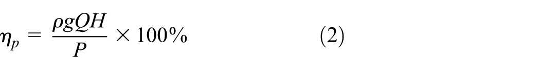
GVFin and GVFout are gas volume fraction at pump inlet and outlet, respectively; ρ is the density, kg/m3; g is the acceleration of gravity, m/s2; Q is the flow rate, m3/h; H is the pump head, m; and P is the shaft power, W.
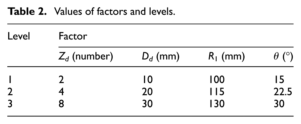
The parameters of exhaust are shown in Figure 4. Zd is the numbers of exhaust, D is the diameter of exhaust, R1 is the radial distance, and θ is the circumferential position. Three levels of each factor and standard L9(34) orthogonal table were chosen for optimal design according to designer’s experience, as shown in Table 2.

Degas parameter schematic diagram.
Values of factors and levels.
Numerical calculation method
Flow channels, turbulence generator, impeller, volute, and vacuum chamber were constructed, and the details are shown in Figure 5.

Flow passage components.
The choice of two-phase flow model is highly depending on the flow regime. Unfortunately, there is currently no multiphase model that can simulate all two-phase regimes simultaneously. Currently, two approaches for multiphase flows exist: the Euler–Lagrange approach and the Euler–Euler approach. In the Euler–Euler approach, the different phases are treated mathematically as interpenetrating continua. The concept of volume fraction occupied by each phase is introduced. The volume fractions of the different phases are assumed to be continuous functions of space and time and their sum is equal to one. Previous simulations have already shown that the volume of fluid (VOF) model is able to simulate the gas separation in multiphase flow pump. The VOF model was selected for these simulations. The turbulence model was the k–ε model, renormalization group (RNG), and swirl-dominated flow. The frozen rotor interface and transient rotor/stator interface between rotating zone and static zone were used to steady and unsteady simulations, respectively. The velocity inlet, static pressure outlet, adiabatic, no slip wall, and scalable wall functions were used, and the wall toughness is 0.05 mm.
The structure mesh was constructed by ICEM, and mesh independency was checked by demonstrating that additional mesh did not change head by more than 5% comparing with design head, as shown in Table 3, and the number of mesh was 3.71 million, and the Y plus arranged from 16.5 to 321 is shown in Figure 6.
Grid independency.


Grid generation.
Discussion
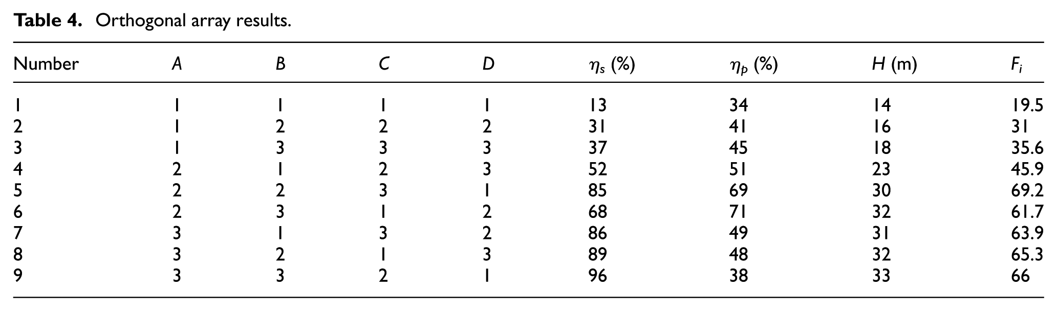
According to factor levels, as shown in Table 1, and standard orthogonal table L9(34), the nine experiments were obtained. A, B, C, D were Zd, D, R1, θ, respectively. The gas–liquid separation efficiency, hydraulic efficiency, and head of MCP at different experiments were indicated by computational fluid dynamics (CFD). Comprehensive performance of MCP was evaluated using a weighted method. The comprehensive performance, Fi, was defined as follows

where ηs, ηp, and h are gas–liquid separation efficiency, hydraulic efficiency, and head, respectively; λ1, λ2, and λ3 are weighted coefficient, and the values are defined as λ1 = 0.5, λ2 = 0.3, and λ3 = 0.5. Gas–liquid separation was guaranteed for MCP so it was major consideration than hydraulic efficiency and head.
Table 4 shows the orthogonal array results. From Table 4, the 5# experiment is the best one in which Fi is 69.2 and ηs, ηp, and h are 85, 69, 30, respectively.
Orthogonal array results.
Since the test of index is three, this was a multi-index orthogonal experiment. For searching the effects of factor on index quickly, the factor in a certain level of quality was evaluated by variance analysis. First, single indicator was analyzed, and then comprehensive analysis was considered. The magnitude of variance reflected the effect of factor level on index. The larger the variance was, the greater the effect of factor level on index was, and the corresponding factor was the main factor.
The variance of gas–liquid separation efficiency, hydraulic efficiency, and head is shown in Table 5, and k1, k2, and k3 were extreme values. For gas–liquid separation efficiency, the influence order of factors is A > B > C > D, for hydraulic efficiency, the influence order of factors is A > C > B > D, and for head, the influence order of factors is A > B > C > D. The conclusion from variance analysis is that A3B2C3D1 is the best option for gas–liquid separation, A2B2C3D2 is the best option for hydraulic efficiency, and A3B3C3D2 is the best option for MCP head. Since amount of gas is in MCP, the gas separation is prerequisite for pumping. Therefore, choosing the best combination of options, the efficiency of gas–liquid separation of MCP should be taken into account first, and then the comprehensive consideration is pump hydraulic efficiency and head.
Range analysis of gas–liquid separation, hydraulic efficiency, and head.

For studying comprehensive performance easily and avoiding changes caused by weighting factors, the dimensionless hydraulic efficiency and head of MCP were investigated using normalized method

The relationship between comprehensive performance and factor is shown in Figure 7. Three levels of factors, Zd, D, R1, θ, were set as abscissa, and comprehensive performance

Response graph for each level of the parameters.
Optimized flow field and validation
Analysis of optimized flow field
The distribution of GVF on front and back of impeller is shown in Figure 8 at design flow condition. Turbulence generator blade number is 1/2 of impeller blades which caused the circumferential distribution of gas into the density interaction in impeller, and major distribution gathers in inlet and suction of blade, while peripheral distribution on impeller is less. The gas concentrates in the back of impeller center. Since impeller separation and vacuum pump, in vacuum chamber the GVF approaches 1, there is little gas in volute.

GVF distribution: (a) back of impeller, (b) front of impeller, and (c) axial plane.
Experimental validation
According to orthogonal experiment, the prototype optimized was produced, as shown in Figure 9, and the profile of stainless steel impeller is shown in Figure 9(a). The performance of MCP prototype was tested in experimental rig, as shown in Figure 10, and the fluid is medium consistency pulp with 10% mass concentration. The pulp pattern was like solid, as shown in Figure 9(c). The performance was studied comparing with original MCP.

Impeller of MCP and prototype: (a) impeller and prototype, (b) MCP, and (c) pulp with mass concentration 10%.

MCP performance test rig. 1. MCP, 2. pressure sensor, 3. vacuum manometer, 4. valve, 5. vacuum pump, 6. one-way valve, 7. sonar flowmeter, 8. valve, 9. storage tank, 10. valve.
Because of particularity of conveying medium, the experimental rig was different with general water pump rig. The experimental rig consisted of storage tank, MCP, inverter motor, pressure gauge, sonar flowmeter, valve, vacuum pressure gauge, vacuum pump, and piping. The vacuum pressure is controlled by an inverter to realize different rotational speeds of vacuum pump. The gas flow rate is controlled by the valve. The pulp flow rate is measured by sonar flowmeter. The parameters of sensor are shown in Table 6.
Sensor parameters.

The performance comparison is shown in Figure 11, and the head, hydraulic efficiency, and gas–liquid separation of MCP with optimized exhaust vent were analyzed (more details can be seen in previous works).19,20 Performances were improved using optimized exhaust vent. For analysis convenience, the characteristics of MCP were studied at flow rate from 0.8Q to 1.2Q. The head, hydraulic efficiency, and gas–liquid separation of MCP were improved 5%, 7%, and 20%, respectively, after optimization.

Performance comparison.
Conclusion
A hydraulic structure of MCP was designed in this article. Parameters of exhaust vent were optimized using orthogonal experiment, and the performance of MCP optimized has been validated by prototype.
The primary–secondary relations of effects of exhaust vent parameters on head, hydraulic efficiency, and gas–liquid separation were indicated and analyzed by numerical simulation. The order of effect on gas–liquid separation is number, diameter, radial distance, and circumferential position. The order of effect on hydraulic efficiency is number, radial distance, diameter, and circumferential position. Comprehensive consideration, the best option is that the number of exhaust vent is 8 and diameter of exhaust vent is 20 mm and radial distance is 130 mm and circumferential position is 15°. The characteristics of MCP are studied at flow rate from 0.8Q to 1.2Q. After optimization, the head was improved by 5%, and hydraulic efficiency was improved by 7%, and gas–liquid separation also was enhanced by 20%.
In the further study, the multi-objects optimization using design of experiment, kriging model, and genetic algorithm will be a useful method to study MCP.
Footnotes
Acknowledgements
The authors thank their research group for helping them in this work.
Handling Editor: Takahiro Tsukahara
Declaration of conflicting interests
The author(s) declared no potential conflicts of interest with respect to the research, authorship, and/or publication of this article.
Funding
The author(s) disclosed receipt of the following financial support for the research, authorship, and/or publication of this article: This study is supported by Sichuan Province Department of Education (grant no. 172467); the Key Project of Xihua University (grant no. Z1620408); Open Fund of Key Laboratory of Fluid and Power Machinery, Ministry of Education, Xihua University (grant nos. szjj2016-001 and szjj2015-016); the Young Scholar Reserve Personnel Project of Xihua University and National Natural Science Foundation of China (grant no. 51379179).