
Abstract
This article presents a novel under-actuated robot hand, which has a thumb and two cooperative fingers. The thumb has two joints with 2 degrees of freedom driven by one motor. Each of the other two fingers has the same mechanism structure with the thumb and forms a cooperative mechanism, which is driven by only one motor with 4 degrees of freedom in total. All the under-actuated fingers are designed with the transmission mechanisms based on a kind of mechanism combined with the linkage mechanism and the passive elements. In this article, it is shown that under-actuated hand is able to reproduce most of the grasping behaviors of the human hand anthropomorphically and self-adaptively, without increasing the complexity of mechanism and control. The grasping stability analysis is given to help to understand the size range and load range of a stable grasp. Finally, the experiment results verify the high efficiency and stability of the novel mechanism.
Keywords
Introduction
For decades, many bionic hands with numerous degrees of freedom (DOFs), small volume, and powerful output have been developed. The research of designing bionic hands is a popular topic since robots need more precise operation with hand in the forthcoming robot age. According to the application, the design of robotic hand can be simply divided into two types, simple hand or gripper for industrial production and dexterous hand for service robot or the upper limb amputee. The former is to reduce or replace the manual operation in industrial manufacturing; the key is focusing on the function and reliability. As the tasks are quite simple, generally there is no consideration in the bionics. The industrial hand may be just a simple gripper, with only one joint for each finger for simplicity, while its main task is to accomplish a simple grasp.
While the dexterous hands are equipped on service robot and humanoid robot where precise operation is needed. In addition to considering the performance problems, bionics, which means the shape and mass similarity compared with the human body, should also be taken into consideration. Dexterous hands can accomplish some accurate grasp and even precise manipulation. Famous dexterous hands include Stanford/JPL hand, 1 Utah/MIT hand, 2 Robonaut hand, 3 Bebionic hand, 4 HIT/DLR II, 5 and the Shadow Hand, 6 which can provide 24 movements to reproduce as closely as possible the kinematics and dexterity of human hand. Dexterous robotic hands have been a perennial research topic, and their goals are almost exclusive to obtain more functions like human hand. However, it has been suggested that using anthropomorphic design approaches is restrictive and ambitious since one tends to copy what nature has produced in millions of years of evolution. 7 Therefore, compromise between versatility and simplicity should be taken into consideration in order to obtain relevant practical systems, 8 and the main focus of this article is on how to improve the anthropomorphosis and the grasping stability of the hand.
Under-actuated (UA) mechanism can be regarded as a novel way to improve the anthropomorphosis and grasping stability of hands.9,10 A hand is considered to be UA if the number of actuators in the hand is smaller than the number of DOF. 11 UA hands have achieved a rapid development in recent years owing to their special characteristics, including the considerable number of joints with only a few actuators applied inside; individual joint torque does not need to be specified a preset value, which reduces the difficulty of control. In addition to the HIT/DLR II mentioned above, the other famous UA hands such as the 15-DOF Laval hand, 12 the SDM hand, 13 and the multifunctional anthropomorphic prosthetic hands are all very representative.14,15
In the prior researches on UA hand structures, Birglen and Gosselin 16 present a three-phalanx UA finger combining linkage mechanism and spring to achieve the self-adaptability, which allows it to adjust itself to irregularly shaped objects. While joint angles between each phalange keep fixed before the proximal phalange touches object, this is obviously not an anthropomorphical way like human. In order to realize the coupled and self-adaptive movement, Li et al. 17 present a two-phalanx finger based on pulley and gear, which can realize coupled anthropomorphical, self-adaptive motion and achieve experimental verification, while the number of the components is up to 16 except the motor in total. Besides the complex structure, the finger can just achieve its own self-adaptability, which means each finger needs to be driven independently to realize the whole hand self-adaptability. The novel UA finger structure proposed in this article is based on Birglen’s research, combining the linkage mechanism and spring, which can realize coupled, self-adaptive motion as the UA finger proposed by Li, while only six components are included. Moreover, an UA transmission mechanism is proposed to connect the independent finger, which makes each connected fingers work in a cooperative way. Therefore, the self-adaptability promotes from an independent finger to the whole hand without increasing the number of actuators. The feature of the proposed hand is similar to Gosselin’s work; however, there are some shortage in tendon-driven mechanism relative to linkage mechanism in practical application, which will be described later. Moreover, in addition to the ability that allows the hand to adjust itself to an irregularly shaped object without complex control strategy and sensors, 16 the grasping stability should also be taken into consideration. This article innovatively puts forward a method of obtaining the grasping stability through calculating the contact force; thus, the range of the grasping static equilibrium is obtained.
This article is organized as follows: section “Design of UA hand” presents the UA transmission mechanism of hand in detail first and then summarizes the grasping process. Section “Force analysis of the UA finger” analyzes the fingers’ grasping forces in different grasp modes. Section “Stability analysis of UA hand” analyzes the grasping stability of the UA hand and shows the range of the static equilibrium. Grasping experiments are illustrated in section “Experiments of the UA hand,” followed by conclusions in section “Conclusion.”
Design of UA hand
In this section, the structure of UA finger is presented first. Then, the grasping process analysis of the single finger and the cooperative fingers will be given.
Structure of UA finger
For an anthropomorphic hand, in addition to owning to many functions, the finger mechanism must be very compact to preserve the overall size. A healthy person’s finger is composed of three phalanges connected with three joints, the metacarpophalangeal (MCP) joint, the proximal interphalangeal (PIP) joint, and the distal interphalangeal (DIP) joint. To compromise the versatility and simplicity, the UA finger proposed in this article only has the MCP joint as the PIP joint, and the DIP joint’s motion is negligible relative to the PIP joint, only about 50% of the PIP joint’s; 18 therefore, the proposed UA finger only contains the proximal phalange and the distal phalange.
Tendon-driven mechanism is widely used in the UA finger mechanism due to its flexibility and simple structure, such as the Shadow Hand and Gosselin’s pioneering work; however, it can only exert small grasping force which is unable to do heavy work. The other disadvantage of tendon systems is that they are strongly affected by friction and elasticity.19,20 Therefore, a linkage mechanism with springs for a finger mechanism was proposed by Licheng and Ceccarelli 21 and Shuangji et al. 22 As linkage mechanism consists of rigid links and transmission gears, it is more convenient for applications where large grasping forces are required, and the finger and hand kinematics can be easily modeled and solved as a standard kinematics problem for control purposes. 23
Figure 1 shows the schematic diagram of the UA mechanism the 3D model of the UA finger and its prototype produced by three-dimensional (3D) printer. The novel UA finger mainly consists of four bars, a base, and a torsion spring. A and B represent the MCP joint and PIP joint, respectively, and C, D, and E represent the other revolute joints of the linkage mechanism, and the torsion spring is located at point E connecting the distal phalange and Link_2. Motor is embedded in the palm with a gear connection at joint C; the torque Ts is transmitted from the motor to rotate Link_1. As the two phalanges’ motion transmission is connected with the linkage mechanism with spring, the finger can realize coupled motion and self-adaptive motion; the grasping process will be introduced in detail later.

(a) Schematic diagram of the UA finger, (b) 3D model of it, and (c) its prototype produced by 3D printer with ABS material. The main parts are presented in (a) and (c).
Grasping process of UA hand
The grasping process of the UA hand is divided into two parts, the individual grasping process of one UA finger and the cooperative grasping process of the two fingers. The grasping process of one UA finger is shown in Figure 2, where the grasping process is simulated through the 3D model of the finger. The process consists of two sequential modes: coupled grasp mode and self-adaptive grasp mode. Figure 2(a) shows the initial state of the finger that all the phalanges are maintaining at the relaxed state like human. When the finger starts grasping work, the motor drives Link_1 to rotate through the gear transmission. Before the proximal phalange contacts the object as shown in Figure 2(b), the finger works at coupled grasp mode. During the coupled grasp mode, the torsion spring keeps its initial state without any deformation, which constrains Link_2 and the distal phalange to be connected fixedly, namely, Link_2 will not rotate relative to the distal phalange at the joint E. When the finger works with the coupled grasp mode, the proximal phalange and distal phalange are assumed to be driven by the four-bar linkage ABCD marked in red line.

(a) Coupled grasp mode, (b) self-adaptive grasp mode, and (c) self-adaptive grasp achieved.
Once the proximal phalange touches the object tightly as shown in Figure 2(b), it cannot rotate any more, namely, the contact point F is assumed to be fixed on the base. In the case that the proximal phalange collides with the object while the distal phalange is still free, the UA finger turns into the self-adaptive grasp mode. In this mode, under the action of torque from motor on Link_2 and the reaction force exerted from the object on the proximal phalange, the torsion spring starts to deform. Thus, rotation of motor can still be transmitted to Link_1 through the four-bar linkage DBEC marked in red line as shown in Figure 2(b). Even though the rotation of the proximal phalange is constrained, the distal phalange can still rotate until it touches the object as well. This four-bar linkage DBEC could meet singularity when segments BE and CE are collinear, where Link_1 cannot drive the distal phalange to rotate relative to the PIP joint anymore, this is the mechanical limitation for the UA finger, while with the force exerted from the torsion spring, the distal phalange will extend when the torque acting on Link_1 from the motor is released. As shown in Figure 2(c), the self-adaptive grasp is achieved.
The self-adaptive movement above is merely for a single finger; in order to further enhance the self-adaptability of the dexterous hand, this article puts forward a cooperative transmission mechanism that connects the independent UA fingers to a UA hand. Figure 3 shows the schematic diagram of the cooperative transmission mechanism for two UA fingers and the cooperative grasping process of them. The gear_1 is fixedly sleeved on the finger shaft and fixedly connected with Link_1. The gear_2 is rotatablely sleeved on the motor shaft. The key part of the mechanism is the torsion spring_2 that connects gear_2 and the motor shaft for both the two fingers, whose stiffness is larger than that of torsion spring_1 embedded in the finger, as shown in Figure 3(b). When the grasp starts, the motor fixed on the palm drives the motor shaft to rotate. As shown in Figure 3(a), before the two fingers touch the object, the motor shaft is assumed to be fixed with gear_2 due to the connected spring_2 and drives the fingers both working in coupled grasp mode. When the hinder finger’s proximal phalange collides with the object, spring_1 of the hinder finger starts deforming first and the hinder finger enters its self-adaptive grasp. After the self-adaptive grasp of the hinder finger is achieved, spring_2 that connects the hinder finger and the motor shaft starts deforming; thus, though the hinder finger is blocked by the object, the motor can still rotate to drive the front finger rotating until its self-adaptive grasp is achieved. Moreover, this protects the motor from being damaged when a sudden impact is acted on the fingers.

(a) Cooperative grasping process and (b) schematic diagram of the transmission mechanism. The main parts are presented in (a) and (b).
The analysis above shows the grasping process of the proposed mechanism. With the cooperative transmission mechanism and the UA finger, the UA hand can not only ensure the anthropomorphism of the grasping process but also be capable to encompass objects of various shapes and sizes, such as a cone. Therefore, this UA hand is able to be applied as an effective end-effector in the unstructured environments.
Force analysis of the UA finger
To achieve an effective grasping, the grasping forces of the phalanges should be large enough to maintain the object grasped stably. Different finger grasping force modes due to the UA characteristic is first presented in the section. In the end of this section, the grasping force of the whole 2-joint UA finger is analyzed in detail, which will be used in the grasping stability analysis.
Classification of grasp mode
As the UA finger has the selfadaptability to grasping object according to its size and shape, which leads the grasping force model to be quite different. Grasping force models of the 2-joint UA finger can be divided into two categories according to the number of the contact points: the entire grasp mode and the fingertip grasp mode. For the entire grasp mode, when the proximal phalange touches the object earlier than the distal phalange, the distal phalange will keep rotating until it touches the object as well. However, this ideal grasping sequence might not always occur, if the distal phalange touches the object earlier than the proximal phalange; therefore, the finger works in the fingertip grasp mode. In the entire grasp mode, both phalanges offer grasping forces on object, while in the fingertip grasp mode, only the distal phalange offers grasping force on object, so the fingertip grasp mode is not quite stable as the entire grasp mode because of the lack of grasping force from the proximal phalange. 17 When analyzing the grasping force of a finger, only contact pressure is considered and the contact friction is ignored. Therefore, the contact force defined in this article is perpendicular to the phalange contact surface. In addition, only positive contact force is considered to be feasible when the finger achieves an effective grasp; if an negative contact force occurs, the corresponding phalange will separate from the object. In the entire grasp mode, the grasping forces F1 and F2 are both positive, while in the fingertip grasp mode, the contact force F1 equals to zero, which means the proximal phalange contact is lost.
Grasping force analysis
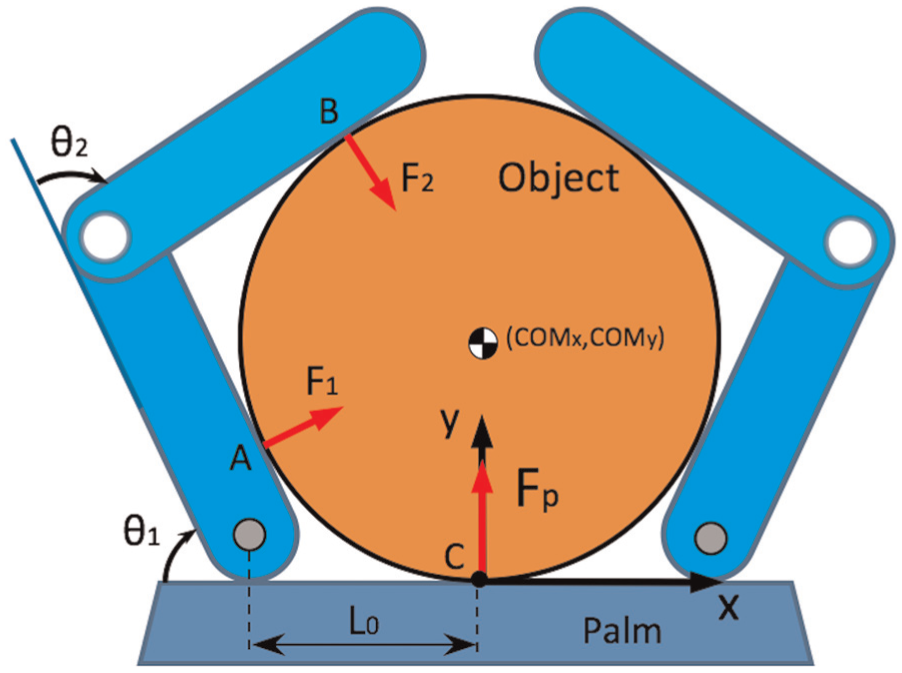
Detailed force analysis will be presented in this section. Figure 4 shows the grasping force model when the UA finger has grasped an object in the entire grasp mode. Although the actual forces exerted on the phalanges are not exactly the same as the diagram, it has the same effect. In the schematic diagram, the proximal phalange length L1 and the distal phalange length L2 are predesigned geometric parameters; F1 and F2 are, respectively, the normal contact forces acting on the proximal phalange and the distal phalange; K1 and K2 are, respectively, the contact locations on their respective phalanges;

Grasping force model of the UA finger.
In order to determine the magnitude of the contact forces that the UA finger can apply to the object, a quasi-static model was developed,16,24 and the following expressions were obtained as equation (1)
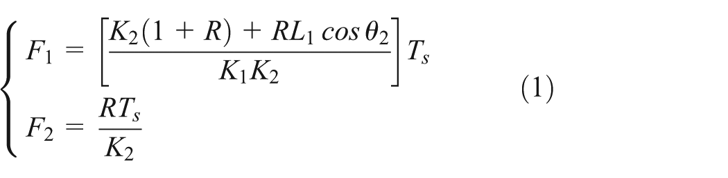
where F1, F2, K1, K2, Ts, Tspr, and
First of all, Link_1 is torque balanced with respect to joint C under the effect of the torque Ts, and forces FL1 and FL2 are the forces exerted on Link_1 and Link_2, respectively. Second, Link_2 is torque balanced with respect to joint C under the effect of

where
At the same time, torque on the distal phalange with respect to the PIP joint B is balanced under the effect of

Finally, the torque on proximal phalange is balanced with respect to the MCP joint under the effect of F1, F2,

where
All of the gravity of the finger is ignored in the analysis as the phalanges’ weights are too small compared with the grasping forces. Assume that when the proximal phalange touches the object, the length of the virtual link BD is

The torsion spring embedded in the finger is ideal which satisfies Hook’s law, so is the torsion spring which connects motor shaft and gear_2 in Figure 3, and the following relationship can be expressed as
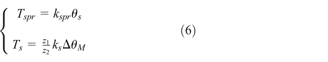
where
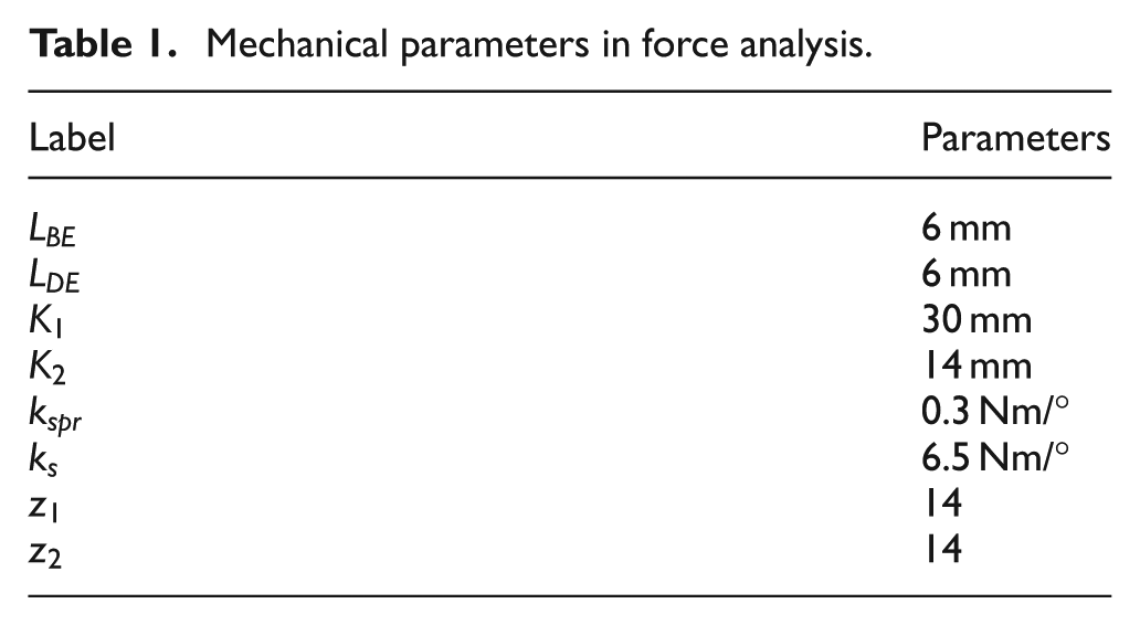
Substituting equation (6) into equations (3) and (4), the grasping force of the finger can be obtained. In order to show the relationship between the contact forces of each phalange and the joint angles of each joint, some required parameters are designed and shown in Table 1. The relationships between the grasping forces and the rotation angles of joints based on the actual finger mechanism are depicted in Figure 5.
Mechanical parameters in force analysis.

(a) Value of the contact force F1 relative to the angles of the MCP joint and the PIP joint and (b) value of the contact force F2 relative to the angles of the MCP joint and the PIP joint.
As depicted in Figure 5(a) and (b), the maximum contact force of the proximal phalange
For the fingertip grasp mode, only the distal phalange touches the object. The force on the distal phalange relative to the joint angles is same as the analysis of the entire grasp mode. The difference is that the proximal phalange reaches its mechanical limitation so the contact force on the proximal phalange
Stability analysis of UA hand
The performance of an UA hand is mainly determined by its mechanical design and to a lesser extent by the control of the hand. 25 The most critical criterion is the grasping stability, in this article it means the range of the rotation of the hand, during which the object is force balanced by the fingers and palm. Grasping stability is constrained by many conditions, including the size, shape, weight of the object, and the posture and contact forces of the UA hand during grasp. In the first half of the section, the objective is to analyze the constraints caused by the parameters of the object in successful stable grasp, such as the size, shape, weight. In the second half of the section, the effect of the posture will be presented, and the grasping stability will also be analyzed.
Grasping range analysis
Due to the UA characteristics of the hand, the hand is able to self-adapt to objects of various shapes and sizes. As the shape of various objects does not have a uniform definition and cannot be calculated reproducibly, for simplicity, all the referred objects’ shape analyzed in this article are supposed to be cylindrical, whose size is characterized by its radius
The range of object sizes which can be grasped by an UA hand depends on the UA finger’s geometric parameters. Due to the symmetry of the mechanism between the index finger and the thumb, the grasped objects keep symmetry relative to them when the palm keeps vertical upward. According to
The five-point grasping model: A, B, and C are the contact points of the object with the phalanges and the palm;
When the objected is entirely grasped by the UA hand, the size of the object is determined by the contact points; in addition, in order to ensure that this is a stable grasping, some constraints must be met. For a five-point grasp, as the object contacts with the palm and phalanges,
The hand gesture can be defined with loop closure vector equations between the object and the phalanges with respect to MCP joint, and the equations are expressed as follows, so are those of the symmetric finger

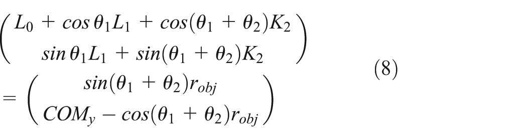
where K1, K2,
This article gives a special case that the hand keeps vertical upward first, and the gestures and the contact forces of the index finger and the thumb are symmetrical. Therefore, the objects are enveloped only if the rotation angles of the phalanges satisfy the following inequality:
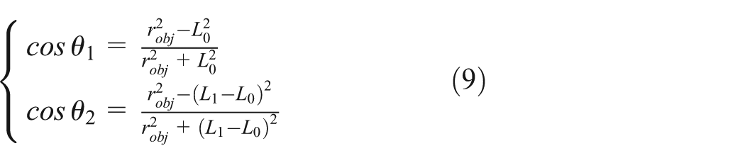
Substituting

All the objects whose
To achieve a quasi-static state of the five-point grasp, the object should be balanced under its gravity and the contact forces of the phalanges and the palm as shown in Figure 6. The contact forces of the phalanges have been analyzed in section “Force analysis of the UA finger,” and its relationship between its values of the joint angles is shown in Figure 5. The contact force of palm is always vertical to the palm as shown in Figure 6. When the object is against the palm, the contact force with the palm must be positive. When the contact force with the palm equals to zero, the hand is in the critical state of four-point grasp and five-point grasp. Obviously, in the case that the object mass is constant, the greater the contact force with the palm, the more stable the grasp. The relationship between the contact force of the palm and the parameters of the object, including the mass and

The relationship between the contact force of the palm relative to the gravity and the radius of the object, and the blue curve is the boundary where the contact force equals to 0 N.
In a five-point grasping, the rotation angles of the joints
As shown in Figure 7, when the object gravity is constant, the smaller the
The case talked above is just the special one where the hand is keeping a vertical upward gesture. However, for a common situation of grasp, the gesture of the hand is not always remaining invariant. Therefore, the rotation of the hand in the 2D plane will be analyzed in this article to imitate the rotation of the wrist. This gesture change makes the gravity of the object not perpendicular to the palm, which will lead the component of the gravity in the y-direction to decreasing, while the component in the x-direction is not still zero; therefore, the symmetry between the index finger and the thumb is broken, so is the original static equilibrium. In order to maintain the five-point grasping state, the object will slide along the x-direction to achieve a new static equilibrium state under the contact forces.
With the inclination of the hand, the object will generate a motion of sliding relative to the palm under the effect of the gravity. As the contact forces cannot guarantee the static equilibrium of the object, the fingers will also change their gestures, namely, the joint angles, the contact points, and the contact forces between the fingers and the object are changed according to the change in the joint angles, which is analyzed in section “Grasping force analysis.” In this process, as the rotation speed of hand is very slow, the acceleration of the object caused by the contact forces and gravity is neglected; therefore, the entire process from imbalance to the static equilibrium is considered to be quasi-static.
The object will eventually remain in three kinds of states: the first is the ideal one that the object maintains in a new static equilibrium under the contact forces and gravity; meanwhile, the five-point grasping is maintained. In the second case, the object can also maintain in static equilibrium under the contact forces and gravity, while some contact forces with palm or phalanges equal to zero, which means that some contact points are lost and the object is not still in a five-point grasping state but in other state mentioned above. The third case is a complete failure, where the finger moves from initial symmetrical position to its limitation, while the contact forces are not able to balance the component of the gravity in the x-direction; finally, the object slip out of the hand. The latter two cases are considered to be failed in this article, and the other grasp equilibrium states in the second case will be analyzed in the future research.
For the successful case, the object will slide on the palm plane with the inclination of the hand, the gestures of the fingers change, their joint angles can be obtained by solving equation (9), and the contact forces between them and the object can be calculated according to equations (3) and (4). In the case of satisfying the contact force with the palm is above zero, the object will keep sliding until the contact forces balance the gravity.
Figure 8 shows the available rotation range of the hand with object of various weights and
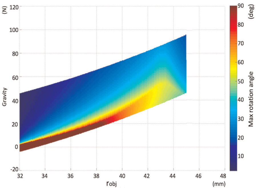
The stable rotation range of the equilibrium state relative to the gravity and the radius of the object.
A simulation is done to simulate the hand rotation in ADAMS, where

Simulation result of the hand rotation, the object is 38 mm radius and 2.43 kg weight, the y-axis represents the contact force of the phalanges and the palm, the x-axis represents the rotation angle of the hand from right to left, the blue curve represents the contact force of the palm, the red and pink solid lines represent the contact forces of the left finger’s proximal and distal phalanges, and the dashed lines represent those of the right finger.
Experiments of the UA hand
Figure 10 shows the self-adaptability of a single finger and the grasp ability of the whole hand. Figure 10(a)–(c) shows the self-adaptability of a single finger to objects of various sizes and shapes, such as ball, cylinder, and cuboid. It is obviously seen that all the objects can be entirely involved by the finger. Figure 10(d) shows the finger working in fingertip grasp mode when grasp is an irregular object. Figure 10(e) and (f) verifies the ability of precision grasping objects of various sizes and shapes presented in Cutkosky’s taxonomy.

Prototype of the UA hand and its grasping process: (a)(c) entire grasp mode for objects of various sizes and shapes, (d) fingertip grasp mode, and (e)(f) precision grasp.
Figure 11 shows a complete grasping motion process of the cooperative fingers driven by one motor. In Figure 11(a), when both the cooperative fingers have not touched the objects, each of their movements is in the coupled grasp mode, and the relationship between the proximal phalanges and the distal phalanges follows the coupled mode; when the hinder finger’s proximal touches the object, its working process mode turns to the self-adaptive mode, and its distal phalange can continue rotating until it touches the object, as shown in Figure 11(c). Due to the cooperative transmission mechanism, the front finger’s movement is independent of the hinder finger’s, as shown in Figure 11(b) and (c), when the hinder finger achieves its entire grasping mode and blocked by the object, the front finger is still working in the coupled mode all the time until the front finger achieves its fingertip grasp mode (Figure 11(d)).

Prototype of the UA hand and its grasping process: (a)(b) coupled mode for the hinder finger and the front finger and (c)(d) self-adaptive mode for the front finger.
The experiment of the UA hand grasping stability is shown in Figure 12; a cylindrical bottle with radius of 42 mm and quality of 3.42 kg is five-point grasped by the hand. In Figure 12(a), the palm is in the state of vertical upward, where the thumb and cooperative fingers keep symmetry, and the contact point with the palm is located at the center of the palm. By rotating the base of the UA hand, the static equilibrium is broken, the bottle starts sliding relative to the palm, and the corresponding changes in the fingers’ postures have also taken place, and the joints’ angles have changed to adjust the contact forces to balance the component of the gravity, as shown in Figure 12(b)–(d), which verified the stability analysis in section “Stability analysis of UA hand.”

Experiment of the grasp stability: (a) the palm is vertical upward and (b)–(d) the static equilibrium during the rotating process of the hand.
Conclusion
In this article, a novel UA hand mechanism is designed and analyzed. The hand can realize human-like operations such as coupled motion and self-adaptive motion. Compared with belt-driven mechanism, the linkage mechanism has simpler structure, while compared with tendon-driven mechanism, the linkage mechanism has bigger grasping force and better controllability. The novel cooperative transmission mechanism promotes its self-adaptability to the entire hand. Grasping force analysis, grasping range analysis, and grasp stability analysis are discussed for the proposed UA hand. Finally, a series of experiments is done to verify the UA hand’s grasping ability. The proposed hand adopts several UA mechanisms, which reduces the hand mass and size while preserving the ability of grasping objects of various sizes and shapes. This is very suitable for the prosthetic fields where accuracy and function requirements are not high, while hand mass and size are strictly limited. As a prosthetic limb end-effector, it could help upper limb amputee do some daily work, such as lifting a briefcase, holding a cup, opening a door. However, the UA hand also has some limitations, such as the simplex mode, which makes it not able to achieve independent movement of multiple DOFs according to the control signals, such as the electromyography (EMG) signals. In addition, it cannot achieve the precise manipulation of the object so that it cannot help to do more complex daily work. Indeed, this article only makes a few steps for analyzing the grasp stability of the novel hand, and some constraints and conditions are simplified or ignored. The friction of the contact model is simplified, while for an accurate model, it is required. The contact model analyzed in this article only contains the power grasp, while for the precision grasp, whose contact points is less than the power grasp, is also very important especially for the precise operation. In the future work, these parameters will be taken into consideration to form a complete method for grasp stability analysis.
Footnotes
Academic Editor: Yangmin Li
Authors note
Xuechao Chen is also affiliated to State key Laboratory of Robotics, Shenyang Institute of Automation, Chinese Academy of Sciences, Shenyang, China.
Declaration of conflicting interests
The author(s) declared no potential conflicts of interest with respect to the research, authorship, and/or publication of this article.
Funding
The author(s) disclosed receipt of the following financial support for the research, authorship, and/or publication of this article: This article was supported by the NSFC of China under grant nos 61533004, 61320106012, and 61673068; Beijing Municipal Science and Technology Project under grant no. D161100003016002; “111 Project” under grant no. B08043; and State key Laboratory of Robotics.