
Abstract
This paper develops a mathematical analysis of contact forces for the under-actuated finger in a general under-actuated robotic hand during grasping. The concept of under-actuation in robotic grasping with fewer actuators than degrees of freedom (DOF), through the use of springs and mechanical limits, allows the hand to adjust itself to an irregularly shaped object without complex control strategies and sensors. Here the main concern is the contact forces, which are important elements in grasping tasks, based on the proposed mathematical analysis of their distributions of the n-DOF under-actuated finger. The simulation results, along with the 3-DOF finger from the ADAMS model, show the effectiveness of the mathematical analysis method, while comparing them with the measured results. The system can find magnitudes of the contact forces at the contact positions between the phalanges and the object.
1. Introduction
Several researchers have investigated different types of devices for grasping and handling unstructured objects. Such a device must adapt itself to the shape being grasped. An isotropic gripper that provides uniform contact pressure is introduced in [1], while the closest gripper to the human finger required more than ten actuators and sensors [2]. Many dexterous hands that have several actuators can be mentioned, such as the Utah/MIT hand [3], the Stanford/JPL Salisbury's hand [4], the Belgrade hand revisited at USC [5] and the DLR hand [6].
As one example of research in the robotic hand field, J.A. Corrales et al. developed the kinematic, dynamic and contact models of a three-fingered robotic hand (BarrettHand) in order to obtain a complete description of the system required for manipulation tasks [7]. Another study by R. Rizk et al. introduced the grasp stability of an isotropic under-actuated finger, which is made by two phalanges, and uses cams and tendon for actuation [8]. They also presented a study of the internal forces developed in the transmission chains. G. Dandash presents the design of a three-phalanx, pseudo-isotropic, under-actuated finger with anthropomorphic dimensions. Two cams were used to ensure grasping was as isotropic as possible [9]. Additionally, for a multi-fingered tele-manipulation system, Angelika Peer et al. presented a point-to-point mapping algorithm, which depends largely on the object identification process and the estimation of human intention. It allows the system to map fingertip motions of a human hand to a three-finger robotic gripper, known as the BarrettHand [10].
The dexterity can also be obtained by under-actuation, which consists of equipping the finger with fewer actuators than the number of DOF. Thus, Thierry Laliberté et al. addressed the simulation and design of under-actuated mechanical hands to grasp a wide variety of objects with large forces in industrial tasks. Architectures of 2-DOF under-actuated fingers are proposed and their behaviour is analysed through a simulation tool. A design of a three-fingered hand is then proposed using a chosen finger [11]. The design of a 3-DOF finger is also discussed with stability of grasp, equilibrium and ejection problems in [12]. In [13], Dalibor Petkovic et al. investigate a kinetostatic model of a design for an under-actuated robotic gripper with fully distributed compliance. Given the highly non-linear system and complicated mathematical model, an approximated adaptive neuro-fuzzy inference system (ANFIS) is proposed for forecasting the gripper contact forces. Moreover, Lionel Girglen et al. analysed several common differential mechanisms modelled as basic force transmission, such as a movable pulley, seesaw mechanism, fluidic T-pipe, and planetary and bevel gear differentials. A mathematical method to obtain the output force capabilities of connected differential mechanisms is presented and two types of under-actuated robotic hands are introduced in [14]. In [15], a fundamental basis of the analysis of under-actuated fingers with a general approach is established. This method proposes two matrices that describe the relationship between the input torque of the finger actuator(s) and the contact forces on the phalanges.
Another approach, LARM Hand, which includes three fingers, was designed for anthropomorphic behaviour. Marco Ceccarelli et al. [16] proposed the grasping adaptation of a 1-DOF anthropomorphic finger mechanism in LARM Hand by using flexible links and/or under-actuated mechanisms with additional spring elements or flexural joints. For a flexible mechanism, flexible links and joints were represented through lumped spring elements, while the under-actuated mechanism was obtained by substituting a crank of the original four-bar linkage with a dyad, whose links are connected by a spring element. In addition, a new finger mechanism with an active 1-DOF was investigated to improve an existing prototype of LARM Hand with a torsional spring at a rotational joint, while a sliding joint is used for the linear spring to achieve a flexible link [17]. The proposed mechanism is not simple since it is composed of seven links, one slider and two springs. In addition, it is requested to be sized within a finger body with human-like size and to operate with an anthropomorphic grasp behaviour.
The introduction of two new matrices in [15] allows the system to calculate the contact forces on the phalanges through the input torque of the finger actuator in the case of full-phalanx grasping. However, in the case of fewer-than-n phalanx grasping, it is difficult to obtain the contact forces based on the relationship between the input torque of the finger actuator and the contact forces on phalanges. This paper proposes a general mathematical analysis of the distributions of contact forces for the under-actuated finger in the case of full-phalanx grasping, while taking into account cases of fewer-than-n phalanx grasping. The simulation results, with the 3-DOF finger model from the ADAMS environment, show the effectiveness of the mathematical analysis method, while comparing with the measured results. The system can find magnitudes of the contact forces at the contact positions between the finger phalanges with the object.
The remainder of this paper is organized in eight sections. The related works are introduced in Section 2. Section 3 reviews the original analysis of an n-DOF under-actuated finger. Section 4 proposes the general contact force analysis of an under-actuated finger. Simulation set-up is introduced in Section 5. Section 6 shows the simulation results. Discussion is mentioned in Section 7. Finally, Section 8 presents the conclusions.
2. Related works
Contact forces play an important role in grasping tasks of the Robot Hand. Contact forces depend mainly on the actuator torque and the torque transmission ratio between under-actuated joints. R. Rizk et al. analysed the contact forces of the under-actuated finger, which is made by two phalanges and uses cams and tendon for actuation. It allows authors to determine the grasp stability of the finger and the efforts exerted on the passive elements, respectively [8]. In [9], G. Dandash presents a method to compute the contact forces in a pulley-tendon finger. It is a matter of establishing a balance between the powers at equilibrium. In another study, Dalibor Petkovic et al. proposed an approximated ANFIS for forecasting the gripper contact forces of the under-actuated robotic gripper with fully distributed compliance because of the highly non-linear system and complicated mathematical model [13].
Several researchers have applied the mathematical analysis to calculate the contact forces in designing the gripper systems. A mathematical analysis to obtain the contact force of the under-actuated gripper was considered in [14]. In [15], the authors propose two matrices that describe the relationship between the input torque of the finger actuator(s) and the contact forces on the phalanges. In addition, Wu LiCheng et al. proposed a static analysis method to obtain the contact forces and a Jacobian matrix of the proposed finger mechanism with an active 1-DOF to improve the existing prototype of LARM Hand [17]. In another approach, the numerical simulation in ADAMS' environment is used to characterize the functionality of the new prototype, which is a new under-actuated finger mechanism for LARM hand [18].
Recently, the sensor technique has been widely developed and applied in the robotic field. Tactile sensors are devices providing pressure data and often surficial distribution of the latter on the sensors; i.e., localization. In [19], the sensor feedbacks from force/torque sensors and tactile sensors were used to implement and validate the robust grasp primitive for a three-finger BarrettHand. In another study, Lionel Birglen et al. implemented the tactile sensors on the MARS prototype finger's phalanges to control under-actuated hands, as shown in Figure 1. The behaviour of under-actuated fingers can be substantially enhanced with tactile information [20].
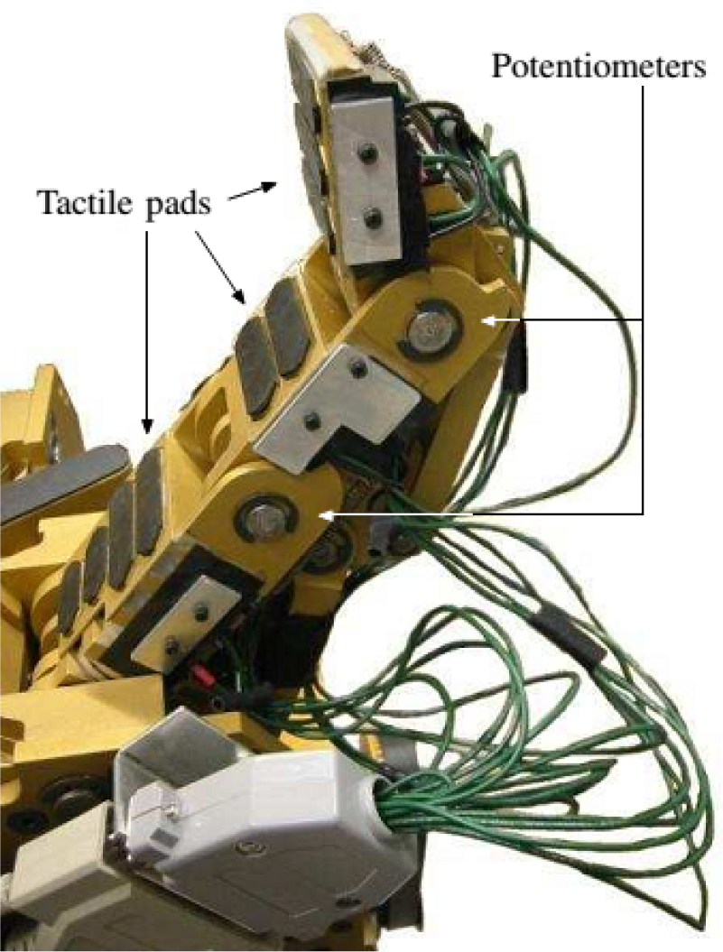
MARS' finger equipped with tactile sensors
3. Review of the original analysis of an under-actuated finger
3.1. General n-DOF, one degree of actuation (DOA) finger
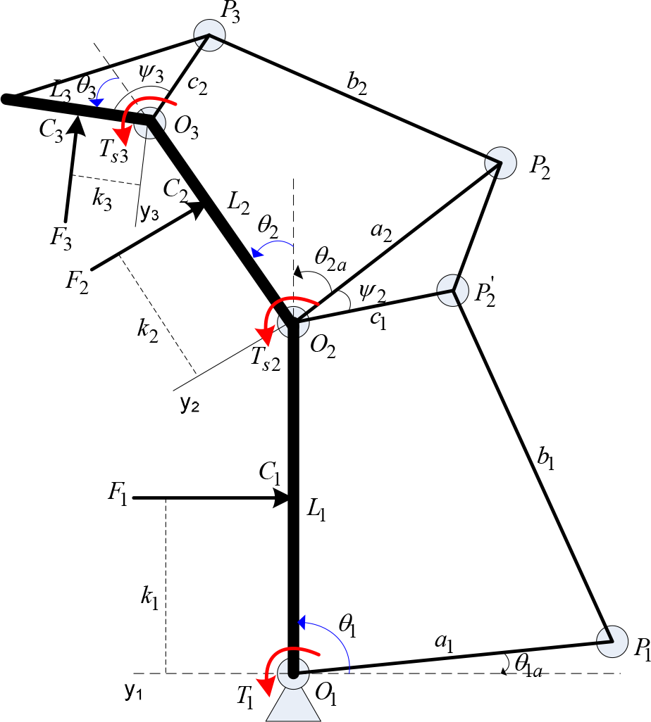
Figure 2 illustrates the type of under-actuated n-phalanx finger considered in this section and all important parameters. The actuation wrench T1 is applied to the input of the finger and transmitted to the phalanges through suitable mechanical elements, such as four-bar linkages. A simple kinetostatic model for the fully adaptive finger with compliant joints can be obtained by adding springs to every joint of the finger. The torque spring
Li = the length of the ith phalanx
ai = the length of the first driving bar of the ith four-bar linkages
bi = the length of the ith under-actuation bar
ci = the length of the second driving bar of the ith four-bar linkages
T1 = the torque of the actuator at the first joint
Fi = the contact force on the ith phalanx
ki = the contact position on the ith phalanx
In previous research [15], Lionel Birglen et al. analysed and discussed the stability of the grasp – i.e., equilibrium and ejection phenomenon, achieving stable grasps and phalanx force distribution, and avoiding weak last phalanges that cannot ensure sufficient force to secure the grasp.

Geometric and force parameters of under-actuated n-DOF finger
3.2. Static analysis of under-actuated n-DOF finger
Even though three phalanges are normally used for robot fingers, this section considers a general n-DOF, 1-DOA finger with four-bar linkages for general static analysis. The finger model is illustrated in Figure 2.
To determine the distributions of the contact forces that depend on the contact point location and the joint torques inserted by springs, we proceed with a static modelling of the finger. Additionally, the friction must be ignored and the grasping object has to be fixed. Equating the input and the output virtual powers of the finger [15] yields:

where T is the input torque vector by the actuator and springs,

where Ki is the stiffness of the torsional spring located at joint Oi, and
Thus, the projected velocities can be simply expressed as a product of a Jacobian matrix JT and the derivative vector of the phalanx joint coordinates

As illustrated in Figure 2, the Jacobian matrix JT of the projected velocities can be obtained in a lower triangular form:

where

and

Through differential calculus, one can also relate the vector to the derivatives of the phalanx joint coordinates defined previously with an actuation Jacobian matrix Ja:

In the under-actuated finger model, the four-bar linkage is used to transmit the actuator torque to each phalanx, while the principle of transmission gives the angular velocity ratio of four-bar linkage, known as Kennedy's Theorem [21–22]. With the ith four-bar linkage

From the last four-bar linkage,

From Equations (8) and (9), Equation (7) can be described by Equation (10) as:

where


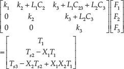
and Xi is a function that is used to transmit the actuator torque to the ith phalanx. Finally, from Equations (1), (3) and (7), we obtain:

which is the equation that provides a practical relationship between the actuator torques and contact forces. Equation (14) is valid if and only if
3.3. Stability of the grasp of the 3-DOF under-actuated finger
We will now analyse the stability of the grasp of the under-actuated 3-DOF finger. The geometric and force parameters under-actuated 3-DOF finger are described in Figure 3, while its real structure design is shown in Figure 4. The identified parameters of the finger are illustrated on Table 1.
The identified parameters of the 3-DOF finger

Geometric and force parameters of under-actuated 3-DOF finger

The structure design of the under-actuated finger
Firstly, the behaviour of the finger is largely determined by its geometry, prescribed at the design stage. Depending on the geometric parameters of the mechanism, one can obtain the final stability of the grasp. Hence, the choice of the design parameters is a very important issue when obtaining stable grasps and a proper distribution of the forces among the phalanges.
The parameters, illustrated in Figure 3, will now be discussed. The length of the phalanges - i.e., L1, L2 and L3 - are fixed from comparison with other existing fingers, simulations and experimentation with a finger model on objects to be grasped. The remaining parameters are ai, bi, ci and
Secondly, the mechanical limit allows a pre-loading of the spring to prevent any undesirable motion of the second and third phalanges due to its own weight and/or inertial effects, as well as to prevent hyperflexion of the finger.
The set of the contact situations pair
Coming back to our issue, the set of parameters presented in Table 1 (which corresponds approximately to the parameters used in prototypes of under-actuated hands [15]), taking into account the mechanical joint limits,
4. The general contact force analysis of under-actuated finger
4.1. Case of n-DOF, 1-DOA finger
According to Lionel Birglen et al. [15], in order for a less-than-n phalanx grasp to be stable, every phalanx in contact with the object should have a strictly positive corresponding force. Actually, the contacts appear not only with all phalanges, but also with fewer-than-n phalanges in object grasping. The corresponding generated forces for phalanges not in contact with the object should be zero, since the latter forces can also be seen as the external forces needed to counter the actuation torque. However, calculating contact forces in the case of fewer-than-n phalanges touching the object by using Equation (14) can be a problem because of the singularity of the JT matrix. This section tries to solve that problem by proposing a general method to determine the distributions of contact forces in all cases of gripper behaviours in object grasping. In order to do that, we assume that the stability of the grasp must be satisfied in all cases.
From Equations (1), (3) and (7), we also obtain:

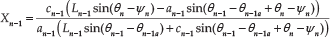
From Equation (15), the component

The left component in Equation (15) can be expressed as:

From Equations (16–17), the general Equation (15) then becomes Equation (18):

Equation (18) shows that the torque

In the case of fewer-than-n phalanges touching the object (e.g., when the ith phalanx is not touching the object), the parameters
Neglect the ith column in the matrix JT because all parameters
Neglect the ith row in the matrix JT because all parameters
Remove the
Neglect the
After neglecting the ith column and ith row, the JT matrix dimension is reduced by
4.2. The case of 3-DOF, 1-degree-of actuation finger
In case of the under-actuated 3-DOF, Equation (14) is valid if and only if
In order to calculate the contact forces, F1, F2 and F3, in the grasping object, we must separate the behaviours between the finger and object into four cases:
Case 1: All three phalanges of the finger contact the object, which means that
From Equation (20), the three contact forces, F1, F2 and F3, are computed by using Equations (21), (22) and (23), respectively.

Case 2: The proximal and distal phalanges contact with the object, which means the parameter k2 does not exist, while F2 is zero, as illustrated in Figure 5b. From Equation (20), the second column and row in the JT matrix relating to the medial phalanx are removed, as well as the elements F2 and

with F1 and F3 then calculated using Equations (25) and (23), respectively.

Case 3: The medial and distal phalanges contact the object, meaning that the parameter k1 does not exist and F1 is zero, as shown in Figure 5c. From Equation (20), the first column and row in the JT matrix relating to the proximal phalanx are removed, as well as the elements F1 and
F2 and F3 are calculated by using Equations (22) and (23), respectively.
Case 4: Finally, the distal phalanx contacts the object, which means the parameters k1 and k2 do not exist, while F1 and F2 are zero, as shown in Figure 5d. From Equation (20), the first and second column and row in the JT matrix relating to the proximal and medial phalanges are removed, as well as the elements F1, F2,

F3 is calculated by using Equation (23).
5. Set-up
5.1. Gripper model set-up
Since the complexity of products has been increasing, in order to increase competition in production, the requirement of the product development cycle times ought to be reduced. Therefore, building a hardware prototype for testing has taken the majority of time for launching new product. The simulation technique based on the virtual prototype is proposed as an approach that significantly reduces manufacturing cost and time, compared to the traditional build-and-test approach. The virtual prototyping approach is an integrating software solution that consists of modelling a mechanical system, simulating and visualizing its 3D motion behaviour under real world operating conditions, and refining and optimizing the design through iterative design studies. The advantages of this simulation technique consist of conceiving a detailed model that is used in a virtual experiment similar to one in a real scenario. Virtual measurements of parameters and components of the mechanical model can also be carried out conveniently. Figure 6 shows the creation of a virtual prototype for testing and simulating the gripper system. The Computer- Aided Design (CAD) drawing of the adaptive gripper was designed by a company in the Republic of Korea.
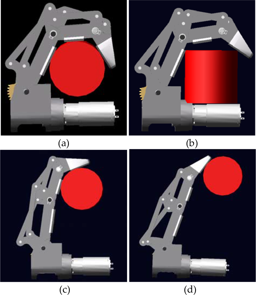
Four cases of finger grasping

Block diagram of ADAM gripper model creation using the Matlab/Simulink Environment
The virtual prototyping platform includes software tools, such as CAD (SOLIDWORKS, CATIA, PROENGINEER), MSC ADAMS and MATLAB/Simulink. The CAD software is used to create the geometric model of the gripper mechanical system. This model includes the rigid parts with the shape and dimension of the physical prototype model, as well as containing information about mass and inertia properties of these rigid parts. The CAD geometry model is then exported to the ADAM/View environment using a file format, such as Step (CATIA) or Parasolid.x_t (SOLIDWORKS). The ADAM/View is the tool of the virtual platform, which is used for analysing, optimising and simulating the kinematic and dynamic behaviour of the mechanical system under real operating conditions.
Constructing a control system for the virtual gripper model is necessary for co-simulation of the two separate simulation programs into a whole system. The control design is developed based on ADAMS/Control and MATLAB/Simulink. To export the virtual mechanical model of the gripper from ADAMS to the MATLAB environment, the input and output variables are firstly defined in the ADAMS model. The input signals are the forces that control the servomotors of gripper fingers. Meanwhile, the output signals are the measured parameters of gear angle, screw speed, joint angles and contact forces. Subsequently, this model is exported to MATLAB/Simulink. In the MATLAB environment, a. mfile and an adams_sys are created. The adams_sys presents the non-linear MSC/ADAMS model with inputs and outputs. In this paper, the ADAMS finger model has a torque input and, 10 outputs, as shown in Figure 7. The ADAMS block is created based on the information from the. mfile.

The ADAM block of finger in adams_sys
The material types of all finger elements and the object, shown in Figure 5, are declared by dry aluminium. Then, the contact feature parameters between phalanges and object are chosen suitably according to the material types under real world operating conditions. Table 2 shows identified contact feature parameters at which the ADAMS contact behaviour resembles the real world contact behaviour.
The identified contact parameters in the ADAMS model

5.2. The simulated control system
Since properly designed under-actuated mechanisms perform shape adaptation “automatically”, no motor coordination is needed. Before performing a grasp, the geometry of the object should be determined and the hand should adjust itself to this geometry by orienting the fingers. To orient the fingers, a simple trajectory is generated to a prescribed position and the gear motor follows this trajectory with a PD/PID position control. In order to set the grasping force on the object, a maximum motor torque is set to a desired value. The relationship between the force on the object and the torque of the motor is obtained using the proposed method to determine contact forces.
In the finger control approach, an integration of position and force control methods for one finger is applied. Figure 8 shows a diagram of the simulated control system. As shown in this figure, the position control system for the finger includes two closed-loop controls: a low-level closed-loop control for motor speed (screw speed) and a high-level closed-loop control for the finger's position angle (gear angle) based on measured motor speed and gear angle feedbacks. For the low-level closed-loop control, the PID controller is applied. Meanwhile, the tuning fuzzy PID (FPID) Controller 1 is designed for high-level closed-loop control because of the non-linear system.

The diagram of the simulated control system for one finger
For the force control system, the tuning FPID Controller 2 is also used, based on the calculated contact force feedback from the Contact Force Detector (CFD) block, where the proposed method to determine contact forces in Section 4 is applied as shown in Figure 8. The inputs of the CFD block are rotating angles of phalanges and driving bars, as well as the measured contact forces and motor torque, while the outputs are three calculated contact forces on three phalanges. As described in Section 4, the distal phalanx of the finger always contacts the object in four cases of finger grasping. Therefore, the contact force on the distal phalanx (F3) is chosen to control for the force control system in four cases.
In finger control strategy, there are two control processes. The first control process is used for the position angle of finger. The torque input of the ADAMS model (τ) is provided by the torque output (
The detailed FPID controller is shown in Figure 9. From this figure, it can be seen that there are three fuzzy tuners for the three output parameters: Kp, Kd and Ki. Two input signals are needed for each fuzzy tuner [23]; namely, the absolute error

The tuning FPID diagram

Membership functions of inputs |e|
Membership functions of inputs |de|
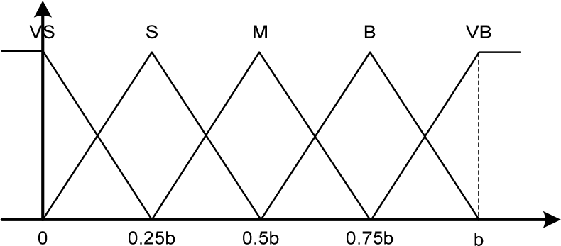
There are three outputs from the three fuzzy tuners, kp, ki and kd, with the outputs having ranges from 0 to 1. Singleton membership functions are then used for the fuzzy output partitions. Figure 12 shows five membership functions (VS, S, M, B and VB) corresponding with the five output states (very small, small, medium, big and very big), respectively.
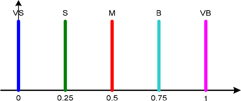
Membership functions of the outputs kp, ki and kd
The design rules of the fuzzy tuners are shown in Table 3. The MAX-PROD formula is chosen as the main strategy for the implication process:
Rule table of the fuzzy tuners

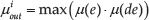
where

where

where
6. Simulation results
We now separate the behaviours between finger and object into four cases, as illustrated in Figure 5. In all cases, the distal phalanx is always the last finger in contact with the object. Therefore, the process follows four steps: Firstly, the input torque of the ADAMS model is issued to move the finger; secondly, the virtual force sensors in the ADAMS model is generated during finger grasping; thirdly, the system will inspect how many phalanges in contact with the object and decide which case of finger behaviour will be used to determine the contact forces; and, finally, the proposed method will to start to calculate contact forces after contact between the distal phalanx and object.
In this paper, two simulations are used to apply the proposed method to determine the contact forces between the phalanges and the object. In the first simulation, the torque input is constant, while contact forces in each case are calculated by the proposal method based on inputs, such as rotating angles of phalanges and driving bars, the measured contact forces and motor torque input. The results are then compared with measured contact forces from the ADAMS model to prove the correctness of the proposed method. The second simulation is to apply the position and force control approaches in order to evaluate the convergence and stability of the system.
6.1. The first simulation results
In the first simulation, there are three input torques for each case:

Contact forces with parameters

Contact forces with parameters

Contact forces with parameters

Contact forces with parameters
Contact forces with parameters

Contact forces with parameters

Contact forces with parameters
Contact forces with parameters

Contact forces with parameters

Contact forces with parameters

Contact forces with parameters

Contact forces with parameters
As demonstrated by our simulation results, in case 1, three phalanges contact the object. From Figures 13 to 15, with three input torques, 1.0[Nm], 1.5[Nm] and 2.0[Nm], the calculated contact forces are very close to the three measured values. For instance, with the input torque T1 =1.0[Nm], the calculated and measured contact forces F1 and
In case 2, the proximal and distal phalanges make contact with the object, which means that there is no contact force between the medial phalanx and object. In turn, the measured contact force
Figures 19 to 24 show the results of cases 3 and 4. Analyses of these two cases are similar to case 2.
Finally, as demonstrated in four cases, the simulation results show that the proposed method is very effective for determining the contact forces in the case of fewer phalanges touching the object in finger grasping.
6.2. The second simulation results
In the second simulation, the integrated control system, which combines the position and force control processes in finger grasping, is used. Firstly, the performance of the position control process is based on the desired angle position inputs until the distal phalanx touches the object, after which the system switches to the force control process. In the force control process, the contact force feedback is the calculated contact force on the distal phalanx, which is made using the proposed method. There are two desired contact forces on distal phalanx in four cases of gripper behaviour:
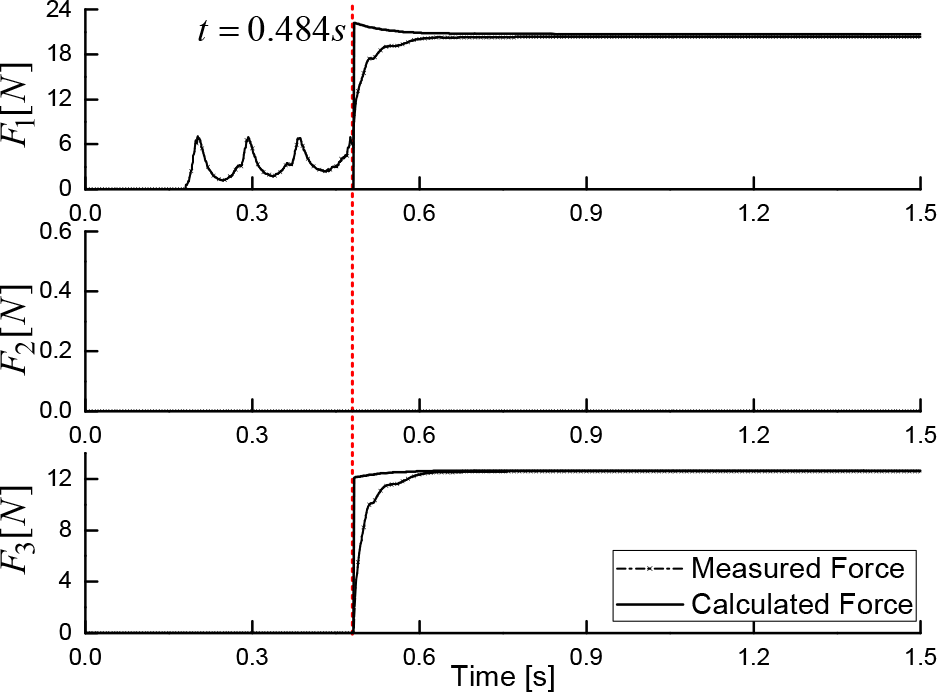
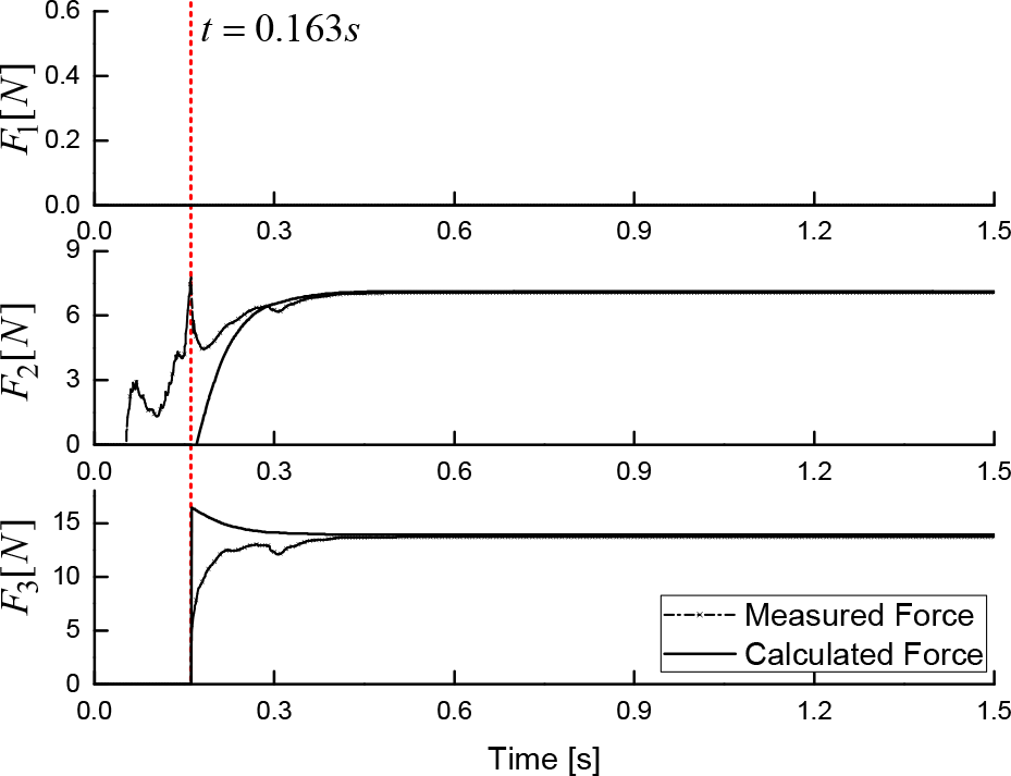
As demonstrated by our second simulation results, in case 1, three phalanges contact the object. Figure 25 shows the desired and real angle position of the finger. It can be seen that the desired value is 1.4 [rad] while the real value comes up to 0.7 [rad] because the finger is prevented by the object. During the time from 0 to 0.65 [s], the real angle is close to the desired value, thereby proving that the position control process works well and is stable. Figures 26 and 27 show the calculated forces from CFD and the measured contact forces from the ADAMS model, as well as comparing with the desired contact forces. For instance, in Figure 26, the calculated force F3 (dash line), after three oscillations, goes to the steady state and is close to the desired contact force,

The desired and real angle positions of finger in case 1
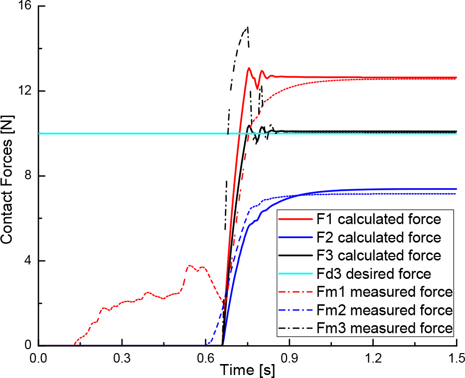
The calculated and measured contact forces of finger with the force feedback control in case 1,
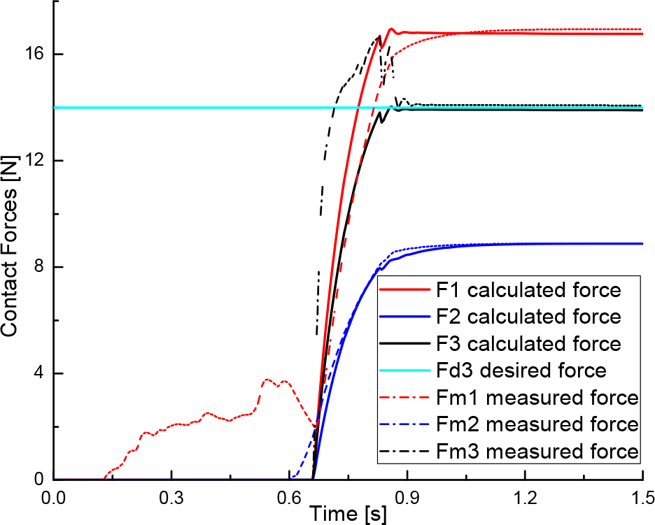
The calculated and measured contact forces of finger with the force feedback control in case 1,
In case 2, the proximal and distal phalanges contact with the object, it means that there is no contact force between the medial phalanx and the object. The desired and real angle positions of the finger are shown in Figure 28. The real value comes up to 0.95 [rad] because the finger is prevented by the object. During the time from 0 to 1 [s], the real angle is close to the desired value, which proves that the position control process still works well and with stably. The calculated forces F3 (dash line) still go to the steady state and are close to the desired contact force,

The desired and real angle positions of finger in case 2

The calculated and measured contact forces of finger with the force feedback control in case 2,

The calculated and measured contact forces of finger with the force feedback control in case 2,
Figures 30 to 36 show the results of cases 3 and 4. Analyses of these two cases are similar to the case 2.

The desired and real angle positions of finger in case 3

The calculated and measured contact forces of finger with the force feedback control in case 3,

The calculated and measured contact forces of finger with the force feedback control in case 3,

The desired and real angle positions of finger in case 4

The calculated and measured contact forces of finger with the force feedback control in case 4,
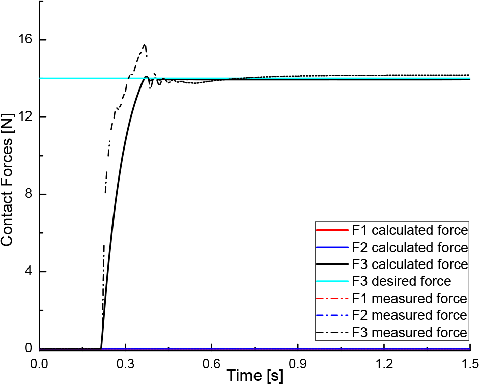
The calculated and measured contact forces of finger with the force feedback control in case 4,
In total, the second simulation results show that the system can perform stably, while the proposed method is very effective for estimating the contact forces as well as in control applications in the case of fewer phalanges touching the object in finger grasping, as demonstrated by four cases.
7. Discussion
The introduction of two new matrices in [15] allows the system to calculate the contact forces on the phalanges through the input torque of the finger actuator in the case of full-phalanx grasping. Configurations of the finger leading to stable grasps are considered by using these two matrices. However, in order for a less-than-n phalanx grasp to be stable, every phalanx in contact with the object should have a strictly positive corresponding force. Actually, the contacts appear not only with all phalanges, but also with fewer-than-n phalanges in object grasping. The corresponding generated forces for phalanges not in contact with the object should be zero, since the latter forces can also be seen as the external forces needed to counter the actuation torque. Moreover, calculating contact forces in the case of fewer-than-n phalanges touching the object by using Equation (14) can be a problem because of the singularity of the JT matrix. The proposed method in this paper, then, solves the above special case. A general mathematical analysis of the distributions of contact forces for the under-actuated finger was presented in the case of full-phalanx grasping, while taking into account cases of fewer-than-n phalanx grasping.
Lionel Birglen et al. believed that static analysis can help refine under-actuated finger designs in term of geometric parameters in order to achieve stable grasps and phalanx force distribution, avoiding weak last phalanges that cannot ensure sufficient force to secure the grasp [15]. Furthermore, with regard to the finger design process, the proposed method provides designers with a tool to select motor specifications (e.g., motor torque) and evaluate the object grasping forces, as well as provide the sensor-based contact force feedbacks for control strategies.
As mentioned in Section 5, the simulation technique based on the virtual prototype significantly reduces manufacturing cost and time compared to the traditional build-and-test approach. The virtual prototyping approach is an integrating software solution that consists of modelling a mechanical system, simulating and visualizing its 3D motion behaviour under real world operating conditions, as well as refining and optimizing the design through iterative design studies. The advantages of this simulation technique consist of conceiving a detailed model, which is used in a virtual experiment similar to a real scenario. Virtual measurements of parameters and components of the mechanical model can also be carried out conveniently. In light of the above reasons, authors have decided to choose the ADAM/View software to simulate the under-actuated finger. This includes real world operating conditions, such as material finger, friction parameters of joints, contact parameters (stiffness, force exponent, damping ratio and penetration depth) between phalanges and object. From the virtual prototyping process, the real system will be manufactured based on the simulation results.
The proposed method in this paper offers good simulation results in determining the contact forces and control application. The system is stable and convergent. Therefore, the proposed method can be applied in the real time experiment. Javier Felip et al. implemented and validated the robust grasp primitive for the BarrettHand gripper based on the sensor feedbacks from torque/torque and tactile sensors [19]. In order to control under-actuated hands, the MARS prototype finger's phalanges has been equipped with Force Sensing Resistors (FSR) to allow experimental testing of the added value of tactile sensing, as shown in Figure 1 [20]. In our gripper system, the potentiometers are installed at the phalanx joints to get the phalanx angles, while tactile sensors provide the contact positions between phalanges and object, while the torque sensors are also applied to measure the input torques. These sensors provide all the parameters needed to apply the proposed method to estimate the contact forces, which will be used to force feedbacks in the finger control strategies. In turn, this provides a low-cost, high performance and easy-to-use operation system.
Given the nonlinear system, intelligent control approaches have been developed, such as the sliding mode controller (SMC) or the Fuzzy Logic Controller (FLC). In gripper control strategy, tactile sensing is of the utmost importance. By using these sensors, one can design a closed-loop force controller and, for example, detect whether the grasping forces are on the edge of vanishing and, in the process, resume the grasping actuation. Moreover, the robustness in grasp task is not only achieved by designing sensor-based controllers, but also by combining several controllers with different optimisation goals. This will be done in real time experimentation in future studies.
8. Conclusions
This paper presents a mathematical analysis to determine the distribution of contact forces for the under-actuated finger in general grasping cases of an under-actuated robotic hand. Due to the importance of the contact forces, the proposed method for static analysis of the distributions of the contact forces focuses on the n-DOF under-actuated finger. The simulation results, with the 3-DOF under-actuated finger from the ADAMS model, show the effectiveness of the mathematical analysis method, as well as comparing the measured results with, especially, the stability and convergence in control application. The system can find magnitudes of the contact forces at the contact positions between the finger phalanges with the object.
Footnotes
9. Acknowledgements
This work(2015.07-2015.12) is the result of a study on the “Leaders INdustry-university Cooperation” Project, supported by the Ministry of Education, Science & Technology(MEST). In addition, this work (2013.03-2014.11) was supported by Development Program of Local Science Park, funded by Ulsan Metropolitan City and MSIP(Ministry of Science, ICT and Future Planning).