
Abstract
Information about the positions of the sensors in sensor networks is very important, and the deployment of more and more sensors is increasing the need for automatic sensor localization. This article therefore describes a novel two-phase ranging algorithm that first obtains rough estimate of the distance to a sensor’s position using time difference of arrival or time of arrival methods and then obtains a high-resolution estimate based on the rough one using a phase-based ranging scheme. This algorithm can easily resolve the otherwise intractable integer ambiguity that often appears in localization systems, and experimental results show that it can greatly decrease the ranging error in a decentralized distance-based localization system having transmitter beacons and receivers in the nodes. Related problems such as signal filtering and multipath effect are also discussed. This algorithm can make the deployment of large numbers of sensors very simple and the determination of their positions so accurate that it would be feasible to use dense networks of sensors to monitor the structural integrity of large structures.
Introduction
Because even earthquake-resistant structures have been destroyed by earthquakes, such as Kobe earthquake in 1995, the ability of structures to withstand earthquakes needs to be checked again using rational design methods. This is the reason that E-Defense facility was built. There the world largest shaking table can reproduce the ground motion of extremely large earthquakes and test the actual performance of full-scale structures.
The EDgrid (short for E-Defense grid) inspired by the Network for Earthquake Engineering Simulation (NEES) project is the cyber infrastructure to support full-scale experiments conducted at the E-Defense facility.1–3 The EDgrid comprises so many devices, including numerous wireless sensors. Usually, sensors are used to be optimizely deployed at the key place of the structures, so that people can use least sensor to catch enough information.4–6 However, with sensors becoming cheaper and cheaper, people begin to deploy large number of sensors at where they have interest. Nowadays, all kinds of wireless sensors are being developed and wireless sensor networks become extremely popular in structural health monitoring (SHM). 7 However, any network of embedded sensors is coupled to the physical world, the sensed structural parameters, such as acceleration and displacement, are often meaningless if we do not know their locations. One therefore needs a high-resolution automatic sensor localization system for monitoring the structural integrity of civil structures.
Localization systems can be range-based and calculate location from estimates of point-to-point distances and angles, or they can be range-free and use only the connectivity and proximity. Range-based localization is more accurate and is therefore widely used in most localization systems. Because the line of sight between a sensor and a reference point cannot always be obtained in or around a civil engineering structure 8 and a small error in angle estimation can result in a very large localization error, in the work presented here, we focused on distance-based localization in which lateration is used to locate a node (Figure 1).
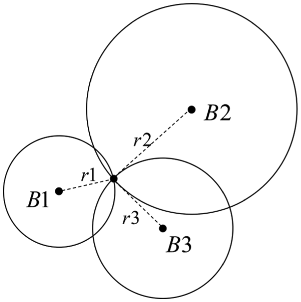
Lateration for distance-based localization.
In literature, several indoor sensor localization systems have already been developed. The active badge system tracks objects in an environment and stores their locations in a centralized database. 9 A badge using an infrared transmitter to transmit its unique ID is attached to each of the objects to be tracked, and the active badge system has a room-sized granularity. 10 In the Bat system, objects are tagged with small radio-controlled ultrasound transmitters, each of which has a unique ID and emits an ultrasound pulse when it receives a radio message with that ID. 11 The locations of these transmitters are determined using the time difference of arrival (TDOA) localization method and are stored in a location database. With this system, 95% of the locations have errors less than 9 cm. RADAR 12 operates by recording and processing signal strength information at multiple base stations positioned to provide overlapping coverage in the area of interest. It combines empirical measurements with signal propagation modeling to determine user location and thereby enable location-aware services and applications. Its median resolution is 2–3 m, about the size of a typical office room. The Cricket location-support system 13 uses a combination of radio frequency (RF) and ultrasound signals to provide a location-support service to users and applications. A listener attached to each item of interest receives RF and ultrasonic signals sent by beacons, correlates them, and infers its current location. The beacons use a decentralized randomized transmission algorithm to minimize collisions and interference among each other, and the listeners use a decoding algorithm to overcome the effects of multipath interference. The Cricket compass, an extension of the Cricket system, however, can determine the location of a device to within about 6 cm. 14
These systems, however, cannot determine sensor location with the precision needed for monitoring structural integrity. Even though there are some high-resolution systems such as laser localization systems, they are very expensive and difficult to be deployed. New sensor localization approach with advanced but practical ranging technology is required to be developed. In recent years, ultrasound is being widely used in TDOA-based localization systems, but the fading of high-frequency sound limits its usefulness to short distances. Also, the good directivity of such high-frequency signals makes it not sensitive to the place which it is not pointing to. These factors result in a small sensing area, in which case, beacons should therefore be densely deployed in the network, which will be very inconvenient for a large-scale civil engineering monitoring system. With these considerations, this article describes a two-phase ranging algorithm improving the localization accuracy of a sensor location system using the audible sound. The ranging process which is most important in localization will be implemented in two steps with its results refined.
Two-phase ranging algorithm
Principle
Consider the way we look for a place in the map. If we want to find the Southeast University, we will find Nanjing city in the national map and then zoom in on it to get the more detailed and exact information we need to find the university. Another more intuitive example of this principle of proceeding from a lower resolution to a higher resolution is the vernier caliper, which is an instrument for making very accurate linear measurements. It utilizes two graduated scales: a main scale similar to that on a ruler and an especially graduated auxiliary scale, the vernier, which slides parallel to the main scale and enables readings to be made to a fraction of a division on the main scale. We first get a low-accuracy reading from the main scale and then get a high-accuracy reading from the sliding vernier that amplifies the measurement accuracy (Figure 2).
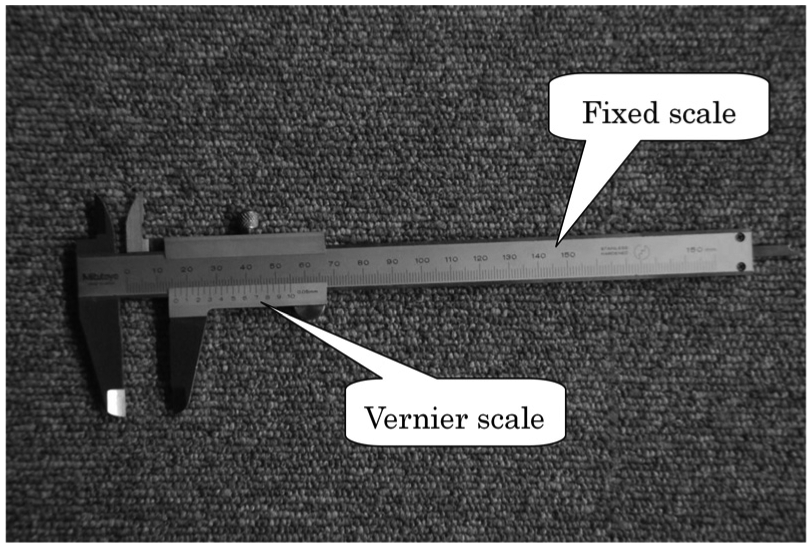
Vernier caliper can get high accuracy using an extra sliding vernier.
The principle of the two-phase ranging algorithm we use to determine the location of a sensor is similar to these examples. We first get a rough distance estimate and based on it get a high-resolution estimate. The rough estimate could be obtained using the TDOA method, and the high-resolution is supposed to be obtained using phase-based ranging method. To avoid fast fading and keep the sensing beam pattern from being too narrow, the proposed localization system tries to use the audible sounds.
Phase-based ranging
Phase-based ranging uses the phase difference to a reference signal to calculate the distance difference and can provide a very high–resolution distance estimate. For this reason, it is used widely in much equipment and systems, such as ultrasonic distance estimators, differential Global Positioning System (GPS), or Real Time Kinematic (RTK). The principle is simple. If a signal has a time delay with reference to another signal, this time delay will lead to a phase delay. Thus, in practice, the time delay can be determined by measuring the phase delay, and the distance can then be calculated from this time delay.
When we denote the received signal s and the reference signal

and

where A and

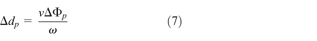
For signal propagation velocity v, the distance difference

In practice, however, we cannot get the exact phase difference because the angular function is a periodic function. Normally, the phase difference is being determined only within a

where

For simplicity, suppose that s and
It is obvious that
Integer ambiguity
From the above discussion, we find that the phase-based ranging method can provide the partial cycle distance with a fairly high resolution. Another problem arises, however, and that is the integer ambiguity. As shown in Figure 3, even though we can get the partial distance, we are not able to know how many whole cycles are there in the whole distance. At least one more condition is required to resolve the integer ambiguity.

A line can be divided by a certain wavelength into integer cycles and a partial cycle.
Let

and

where n is the integer ambiguity (i.e. the number of whole cycles),
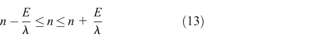
Assume that the measurement error e is always within the permitted error range with the error bound E

Substituting equations (8) and (9) into equation (10) yields the following

which can be rewritten as follows
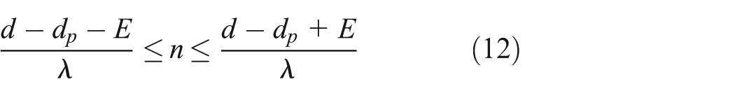
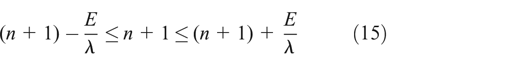
Substituting equations (8) and (9) into equation (12) yields the following
Similarly, we have the following

and
If there is to be a unique integer ambiguity n, the above three inequalities should have no overlapped area in the solution domain. This leads to another two inequalities
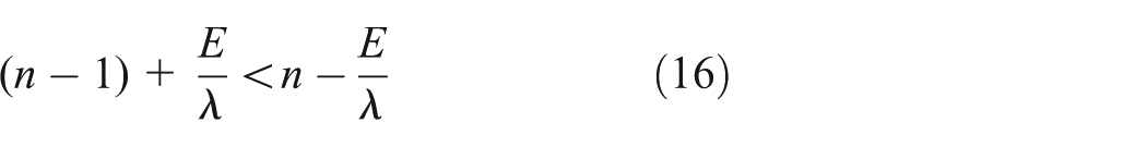
and

Solution of inequalities (equations (16) and (17)) gives the following
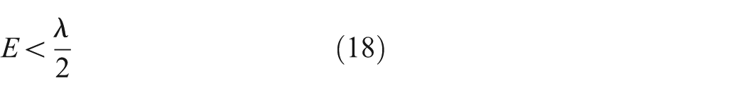
Inequality (equation (18)) shows that if the error of the rough distance estimate is within a half wavelength of the testing signal, the integer ambiguity problem can be resolved easily.
We cannot actually ensure that every rough distance estimate will be accurate to within a half wavelength if the wavelength is not very big. In this case, the integer ambiguities calculated for measurements whose errors are larger that

Integer ambiguity error analysis.
Sensor localization with two-phase ranging algorithm
The localization system is designed as shown in Figure 5. The beacons are deployed on the ceiling, and each one can send an RF signal and a mixed audible sound simultaneously. The RF signal contains the beacon information (ID number, location, etc.), so a node receiving this RF signal can know which beacon is sending the signal and where that beacon is located. Because the RF signal and the audible sound are sent simultaneously and RF signals propagate much faster than sound does, a node receiving the RF signal can immediately set a time stamp and prepare to receive the sound. After the sound signal being received, with the beforehand time step, the TDOA between the RF signal and the sound could be calculated.

Sensor localization with two-phase ranging algorithm.
In the TDOA calculation procedure, the announcement of the arrival time of the sound signal is extremely important. However, sound signal has a rising process at the beginning part of the received signal. The quicker it rises up, the more accurate announcement of the sound arrival could be obtained. Considering a higher frequency sound will rise up much quicker than a lower frequency sound; in this point of view, a higher frequency sound should be applied for the TDOA calculation in order to increase the ranging accuracy for the first step process. Of course, the higher the frequency, the severer it will fade, we still need to consider the balance. In the second step, however, in order to solve the integer ambiguity problem, the wavelength of the sound cannot be too small, and it should be large enough to tolerate the ranging error in the first step. Thus, in this point of view, a lower frequency sound is required to be used to get a good partial cycle estimate in the second step. For such consideration, we propose to send a mixed audible sound, containing a high-frequency sound (e.g. 7500 Hz) and a low-frequency sound (e.g. 1000 Hz). The high-frequency sound is used to estimate the rough distance according to the TDOA scheme, and the low-frequency sound is used to get the high-resolution partial cycle distance estimate using the phase-based method. A high-resolution estimate of the whole distance is obtained by combining these two estimates. After the distance estimate is acquired, the range-based localization algorithm can be used to locate the node.
This system can be decentralized because beacons are the transmitters and the receivers are in the nodes. When a beacon sends a mixed signal, all the nodes can listen to it and get the distance estimates. The beacons need to send signals one by one. We can let the beacons compete to talk (send signals) or let them talk according to the sequence of their ID numbers.
The flow chart of this sensor localization system with a two-phase ranging algorithm (Figure 6) can be described as follows:
A beacon gets the right to talk (send signals).
The beacon sends an RF signal that contains beacon information and simultaneously sends a mixed audible sound that has high-frequency (e.g. 7500 Hz) and low-frequency (e.g. 1000 Hz) components.
All the nodes receive the signals.
When the mixed sound reaches a receiver, it is separated by two filters into two components. A high-resolution distance estimate is obtained using both of them.
All the nodes are located using the range-based localization scheme.

Flow chart of the localization with the two-phase ranging algorithm.
Discussion
Phase delay acquirement
A phase difference is usually obtained using a phase detector, which is often used as a component of a phase-locked loop. The principle of a phase detector is shown in Figure 7.
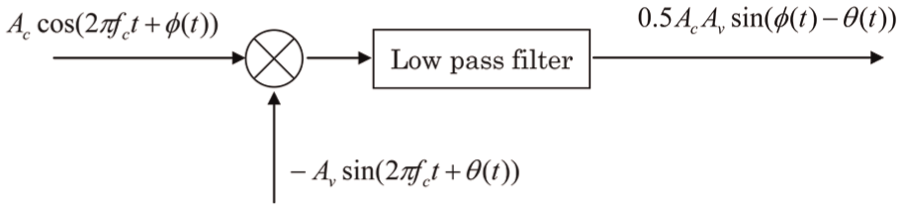
Phase detector.
A phase detector works well when the amplitudes of the two signals are stable, but to avoid the multipath affect, we need to obtain the phase delay at the beginning of the signal. The increasing amplitude of the signal received then will distort the measured difference. Moreover, a phase detector can usually tell us phase difference only within the range of
In our system, the phase delay is obtained by finding relevant peak points of the received signal and a reference signal as shown in Figure 8. When a receiver gets an RF signal, it immediately sets a time stamp and generates a virtual reference signal. When the mixed signal arrives, the phase delay is obtained by finding the relative peak points of the received signal and the reference signal. The reference signal can be a virtual one. We need only to calculate the serial sampling index for the peak points of the reference signal.
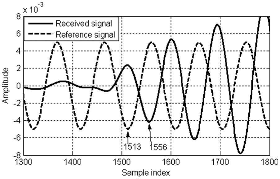
Phase delay acquirement.
Filters
The system uses filters to separate components of the mixed sound. When the mixed sound is received, it will go through two filters, respectively, one passing through a filter with a high-frequency passband (e.g. central frequency = 7500 Hz) to extract the 7500-Hz component and the other passing through one with a low-frequency passband (e.g. central frequency = 1000 Hz) to extract the 1000-Hz component. Filters usually have two unwanted effects, however. One is that when a signal passes through a filter, the beginning of the signal will be strongly attenuated, making it very hard for us to identify the actual start of the signal. The other is that the phase may be changed when a signal passes through a filter, making the calculation of phase delay incorrect. For the digital finite impulse response (FIR) filter, the attenuation problem could be alleviated by applying low filter order, and phase change can be eliminated by adjusting the phase responses to
In this system, however, a wavelet filter will be applied. As we know, a wavelet itself can be regarded to be as a band-pass filter. The most attractive characteristic of a wavelet filter is that the beginning of a signal passing through one is almost distorted-free. The effects of an FIR filter of order 13 and a coif4 wavelet filter can be compared in Figure 9, where it could be found that the FIR filter clearly delays the signal but the wavelet filter does not. The delay of signal’s arrival is due to the attenuation of the beginning part of the signal when the signal passes through an FIR filter, which is caused by the working mechanism of the FIR filter. Usually, the bigger is the order of the FIR filter, the severer the attenuation of the beginning part of the signal will be. It is also found that the FIR filter does not change the signal’s actual amplitude except for the beginning part. When the signal passes through the wavelet filter, however, it seems that the signal amplitude is amplified after the filtering.

Filter effects.
Considering the fact that noises are always unavoidable in the real application, especially when the audible sound is applied, filters are not only needed to extract the target frequency components, but getting rid of the noise is also a very important task. Before designing the system, real site environment should be studied carefully. The designed sound signal should avoid the main frequency band range of the environmental noise. Checking whether it is a stable signal or just a short time random noise at the receiver is also necessary.
Multipath effect
Multipath propagation is always a problem for localization systems, especially for indoor localization systems. The signal will be reflected and diffracted by walls and other objects. Normally, it is very hard for us to distinguish whether the signal we receive is only the direct path signal or is a mixed signal including direct path, reflected, and diffracted components. The multipath effect can strongly degrade the accuracy of the localization result.
The multipath effect could be avoided using the threshold method to catch the first pulse which has the shortest path from the transmitter to the receiver. This is one reason that the Cricket system uses this method. Since the proposed system in this article uses the phase delay to get the high-resolution partial cycle, more attention should be paid because the multipath effect could distort the phases. It could be avoided by measuring the phase delay at the beginning of the signal, which is determined using a threshold. The threshold is also used in the TDOA scheme giving the rough distance estimate.
Since the amplitude of the received signal is always increasing at the beginning of the arrival, the amplitude of a multipath component arriving a little later is much smaller than that of the direct path component at the same time. A reflected signal will also be weakened to some extent. Here, the effect is considered when there is only one multipath component, and Figure 10 shows that for various amplitude ratios (the amplitudes of multipath component divided by the amplitude of the direct path signal), the phase shift occurs with respect to all the possible phase differences between the direct path and indirect path components. It could be found that the maximum phase shift is larger for larger amplitude ratios.
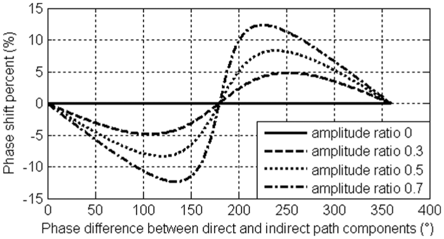
Phase shift due to the existence of multipath component, with respect to the phase difference between direct and indirect path components.
Experiments
To verify the proposed two-phase ranging algorithm, some simple experiments were conducted, in which a mixed sound signal is applied with a 7500-Hz sound used to get the rough distance estimate and a 1000-Hz sound to get the high-resolution partial cycle distance estimate. These sound signals were produced using MATLAB, and the sounds were emitted by a speaker. The sounds were caught by a microphone and sampled with a 48 kHz sampling rate by the sound board of a computer. The experimental setup is shown in Figure 11.
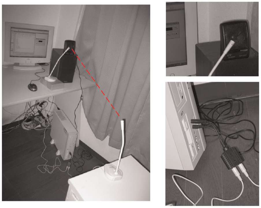
Experimental setup.
The most difficult thing in such experiments was to achieve the time synchronization which is necessary for using the TDOA scheme to estimate the rough distance. Although this time synchronization would be easily accomplished using the RF signal in an actual implementation of the proposed system, we try to realize it with a simple and easy way in our verification experiments. Instead of implementing the RF transmitter and receiver which may make the experiment a little complicate, an extra (secondary) microphone is deliberately deployed just before the speaker to catch the sound. Thus, the time the sound is caught by the secondary microphone could be regarded to be the start time of sending the mixed sound. The time difference of the sound’s arrival between the two microphones could be regarded as the travel time of the sound, with which the distance could be estimated. Such process simulates the TDOA process of getting the rough distance at the first stage, as shown in Figure 12.

Simulation of TDOA process of getting the rough distance.
The mixed sound received was sampled by the sound board of the computer, filtered to extract the high-frequency and low-frequency components, and used to calculate the distance between the speaker and the primary microphone. One can see from the results listed in Table 1 that in both experiments, the second (calibrated) phase of our two-phase algorithm had a much smaller ranging error. The results show that the proposed approach could refine the ranging result.
Ranging result using the proposed method.

TDOA: time difference of arrival.
Conclusion
To increase the accuracy of range-based localization schemes, we use a two-phase ranging algorithm to decrease error of their distance measurements. A rough estimate of the distance between a beacon and a node is first obtained using the TDOA method, and then, a high-resolution estimate based on the rough one is obtained using a phase-based ranging scheme. The results of simple experiments showed that this two-phase ranging algorithm can decrease the ranging error. This algorithm can simplify the deployment of sensors and can determine their locations so accurately that it would be feasible to use dense sensor networks to monitor the integrity of large structures.
Footnotes
Acknowledgements
The authors would like to express their great gratitude to Prof. Akira Mita at Keio University for his kind guidance and support.
Academic Editor: Jun Li
Declaration of conflicting interests
The author(s) declared no potential conflicts of interest with respect to the research, authorship, and/or publication of this article.
Funding
The author(s) disclosed receipt of the following financial support for the research, authorship, and/or publication of this article: This research was supported by the National Science Foundation of China (no. 51578140), National Key Technology Research and Development Program of the Ministry of Science and Technology of China (no. 2014BAG07B01), and Open Fund of Key Laboratory of Concrete and Pre-stressed Concrete Structure of Ministry of Education (CPCSME2015-01).