
Abstract
In this study, a new sub-shift schedule was proposed for a hydro-mechanical transmission. To develop the sub-shift schedule, a network analysis was performed by considering the hydrostatic unit loss and mechanical component losses. In the new sub-shift schedule, the sub-shift gear can be selected with respect to the demanded wheel torque and vehicle speed, which provides improved system efficiency for the given vehicle operating condition. Since the sub-shift can only be carried out at a speed ratio where the off-going and on-coming clutch speeds are synchronized in the existing sub-shift control, a sub-shift control algorithm without the clutch speed synchronization was proposed to apply the new sub-shift schedule using the forward clutch pressure and hydrostatic unit stroke control. The performance of the sub-shift control algorithm without the clutch speed synchronization was evaluated by the simulation and experiment. It was found from the simulation and experimental results that the sub-shift can be achieved, showing an acceptable peak-to-peak torque variation in the driveshaft.
Keywords
Introduction
To improve fuel efficiency and provide enhanced convenience for workers, many studies have been conducted on tractor transmissions. Among them, hydro-mechanical transmission (HMT) is expected to be a viable solution since it can provide improved fuel efficiency by changing the engine operation point on the high-efficiency region using the continuously variable transmission (CVT) function, and it offers convenience in its working operation due to its automatic shifting feature. The HMT transmits the engine power through the mechanical path and hydraulic path using the planetary gear and hydrostatic unit (HSU). The HMT transmits relatively higher power with higher efficiency than the hydrostatic transmission (HST). Because of these advantages, many tractor manufacturers have developed their own type of HMT.1,2
The HMT consists of an HSU, planetary gear sets, and sub-shift part. The engine power is split at the planetary gear and is transmitted to the sub-shift gear. The sub-shift gear provides an expanded gear ratio range. The sub-shift gear is composed of multi-step gears, which are implemented by the clutch and brake operations.
In the target HMT, the sub-shift is performed at a specific speed ratio of the HMT, where the speeds of the on-coming gear (clutch) and off-going gear are synchronized using the on/off clutch.3–6 Otherwise, the shift shock occurs due to the speed difference between the on-coming and the off-going clutch. In a conventional automotive transmission, the shift point is determined by considering the system efficiency with respect to the vehicle speed and acceleration pedal position. However, in the target tractor, the shift point is determined according to the HMT speed ratio regardless of the efficiency.
For the control of the HMT with multi-speed sub-shift gears, various studies have been performed including the shift logic and tractor velocity control for the HMT with two-speed sub-shift gears, 3 control architecture of the HMT using proportional–integral (PI) control and current compensation, 4 sub-shift schedule to obtain the maximum driving capacity and to prevent the shift circulation due to the frequent shift, 5 and HSU control for the sub-shift of the HMT with dog clutch. 6 For smooth sub-shift, control strategy of the HMT was investigated based on the orthogonal test. 7 In most of the aforementioned works, the sub-shift is only possible under the constraint that the sub-shift should be carried out when the clutch input and output speeds are synchronized.
The HMT efficiency varies depending on the speed ratio and input power.2,8 The power in the HMT is transmitted through the hydraulic path and mechanical path and the efficiency of each path depends on the hydraulic and mechanical component losses. 8
Therefore, to perform a sub-shift-to-a gear ratio that provides better HMT efficiency, a new sub-shift schedule is required that considers the HMT efficiency, and a sub-shift control algorithm that can be applied using the new sub-shift schedule needs to be developed.
In this study, a sub-shift schedule that provides more efficient HMT operation and a sub-shift control algorithm without clutch speed synchronization were proposed. To derive the sub-shift gear schedule, power losses of the hydraulic path and mechanical path were calculated including the transmission components. The efficiency of each sub-shift gear was compared and a new sub-shift schedule was developed. To apply the new sub-shift schedule, a sub-shift control algorithm was developed using the forward clutch pressure and HSU stroke control without the clutch speed synchronization.
Configuration of the HMT
Figure 1 shows the configuration of the target HMT and transmission components. The target HMT consists of two planetary gears (PG1 and PG2), an HSU, four sub-shift clutches (CL1–4), and forward (FWD)/reverse (REV) clutches. The engine is connected to the sun gear of the first planetary gear and power take-off (PTO) shaft. When the tractor operates with the attachment in the PTO workings such as the baler and rotary workings, the engine power is directly transmitted through the PTO shaft to the attachment, which is connected to the PTO shaft. The hydraulic pump of the HSU is driven by the engine. The hydraulic motor of the HSU is connected to the ring gear of the second planetary gear. When the odd sub-shift clutch (first or third) is engaged, the power from the engine is transmitted through the carrier of the planetary gear set. When the even sub-shift clutch (second or fourth) is engaged, the power flows through the second sun gear of the planetary gear.

Configuration of the target HMT.
For the dynamic model of the powertrain, the inertias of the engine, hydraulic pump, hydraulic motor, sub-shift shaft, and vehicle were considered (Figure 1). The dynamic equations of the target HMT are derived as follows


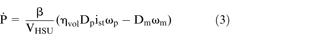


where J is the inertia, i is the gear ratio, η is the efficiency, D is the HSU displacement, P is the pressure, V is the volume, m is the mass, and r is the radius. The subscripts e, ep, p, mech, st, vol, m, and mR represent the engine, from the engine to the pump, the HSU pump, mechanical efficiency, HSU stroke, volumetric efficiency, HSU motor, and from the motor to the ring gear, respectively. The subscripts sub, CL, wh, FWD, RGs, DS, and load indicate the sub-shift shaft, clutch, wheel, forward gear, reduction gears, driveshaft, and the load, respectively. The numbers combined with CL represent the sub-shift gear number. The HSU stroke (ist) is defined as the ratio of the HSU motor speed (ωm) to the pump speed (ωp) as ist = ωm/ωp. The mechanical efficiency and the volumetric efficiency of the HSU were obtained from the experiments. 8
From equations (1)–(6), the driveshaft torque TDS of the second sub-shift gear (even shaft) and third sub-shift gear (odd shaft) can be represented as follows


where
The HSU stroke ist in equations (2), (3), (7), and (8) is determined by the HSU swash plate angle. The swash plate angle is controlled by the solenoid valve and linkage mechanism. The dynamic model of the HSU stroke can be represented as a second-order system as follows

where K is the system gain, Td is the time delay, ζ is the damping ratio, and ωn is the natural frequency. The subscript cmd represents the command value. The parameters of the transfer function (equation (9)) were determined from the time domain analysis in Figure 2(a) and verified in the frequency domain (Figure 2(b)). It is seen from Figure 2 that the second-order transfer function shows a good agreement with the experiments.

Comparison of the transfer function with experimental results. i st : HSU stroke; i st_cmd : HSU stroke command.
Modeling of the HMT losses
The efficiency of the HMT changes depending on the engine power, speed ratio, and the sub-shift gear. In PTO workings, since a constant speed is required for the attachment, the engine and vehicle speeds need to be maintained at a constant value, in other words, at a constant speed ratio. In this working condition, if the HMT is operated at a sub-shift gear that provides better system efficiency, improved fuel economy can be achieved. In this study, to find a sub-shift schedule that provides better system efficiency for the given wheel load and speed, HMT losses were investigated, including the HSU loss and mechanical losses.
HSU loss
The HSU in the target HMT is composed of a variable displacement type of hydraulic pump and a fixed displacement type of hydraulic motor. The speed and torque of the HSU depend on the volumetric efficiency (ηvol) and the mechanical efficiency (ηmech) as follows


where ω is the rotational speed, T is the torque, and ist is the HSU stroke. The subscripts m, p, vol, and mech indicate the motor, pump, volumetric, and mechanical, respectively. Sign(Tp) represents the direction of the power in the HSU.
The mathematical models for the loss of the hydraulic pump and motor were proposed. 9,10 However, in this study, an HSU efficiency map (Figure 3) was used, which was obtained from the experiment. In the experiments, the HSU efficiency was measured for various HSU stroke and input speed at the oil temperature of 20°C. Since the tractor can be used in variable environmental conditions, the HSU efficiency map needs to be constructed for various temperatures in the actual application.

Mechanical and volumetric efficiency of the HSU (ΔPHSU = 400 bar).
Mechanical component loss in the HMT
The target HMT consists of mechanical components such as gears, clutches, shafts, and bearings. In the mechanical components, load-dependent loss and no-load loss occur. Both losses vary depending on the torque and speed, in other words, the power changes with the sub-shift gear. In this study, to analyze the mechanical losses of the HMT, individual models of each loss were derived based on the mathematical governing equations and experiments.
Bearing loss
There are two types of bearing loss: (1) no-load loss which depends on the rotational speed of the bearing and (2) load-dependent loss which is proportional to the bearing load.11–13 The bearing torque loss is calculated as follows12,13


where f0 and f1 are the coefficients for the no-load loss and load-dependent loss, respectively; v is the kinematic viscosity of oil; dm is the bearing mean diameter; and F1 is the equivalent bearing load. The subscripts BL0, BL1, and BL represent no-load loss, load-dependent loss, and total bearing loss, respectively. Forty-six bearings are used in the target HMT. The equivalent bearing load is obtained from the force equilibrium and moment equilibrium for each shaft.
Figure 4 shows the power flow and free-body diagram of the odd shaft at the first sub-shift gear. The third gear rotates freely because the third sub-shift clutch is not engaged. At the first sub-shift gear, the torque from the carrier of the planetary gear comes into the odd shaft (Tin) and goes out to the sub-shift shaft through the first sub-shift gear (Tload). There are six bearings (B1–B6) in the odd shaft. The equivalent load (F1) of each bearing can be calculated using Tin and Tload. Since spur gears were used in the target HMT, only the radial direction was considered when calculating the equivalent bearing load.

Power flow and free-body diagram for the odd shaft at the first sub-shift gear.
Gear loss
The gear loss is separated into friction loss and churning loss. The rolling and sliding frictions cause the gear friction loss on the contact surface, and its magnitude is proportional to the torque transmitting through the gear. 14 The target HMT uses a spur gear, which has an efficiency of 98%–98.5% in general. 15 In this study, the gear friction loss was obtained assuming that the efficiency of the spur gear is 98%.
The gear churning loss occurs due to the viscous friction of the lubricant oil. Its magnitude is determined from the rotational speed of the gear, the emersion depth in the lubricant oil, and so on. There are many studies to calculate the gear churning loss.16–18 In this study, the British Standards formulas are used 18

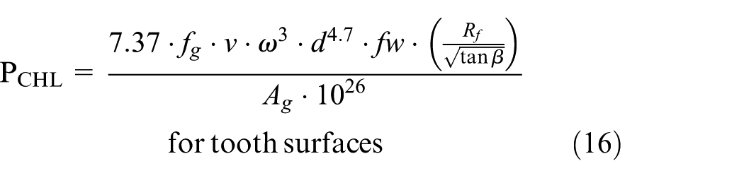
where PCHL is the power loss for gear churning, fg is the gear emersion factor, d is the diameter, fw is the face width of the gear, Ag is the arrangement constant, and β is the helix angle. Rf is the roughness factor.
The gear churning loss is calculated as the sum of the loss for the smooth sides of the gears and the loss for the toothed surfaces using equations (15) and (16). An emersion factor fg = 1 was used when the gear was fully submerged, and fg = 0.5 was used when the gear was submerged halfway.
Clutch drag torque
The wet-type clutch was used for the sub-shift and FWD/REV clutches in the target HMT. A lot of research discusses the mathematical model for the clutch drag torque.14,19,20 In this study, an alternative shrinking model 14 was used to calculate the clutch drag torque as follows

where Tdrag is the drag torque, N is the number of clutch plates, µ is the absolute viscosity, h is the clearance between clutch plates, rS is the equivalent effective radius, and r i is the inner radius of the clutch.
The equivalent effective radius depends on the centrifugal force of the clutch, the viscous force, and the surface tension forces. When the relative velocity of the clutch is low, the oil film between the clutch plates is maintained at full immersion because the viscous and surface tension forces are larger than the centrifugal force. For that reason, the equivalent effective radius is the same with the outer radius of the clutch at a low relative velocity. However, when the relative velocity of the clutch is high, the equivalent effective radius becomes smaller because the oil film is decreased. The equivalent effective radius is calculated as follows
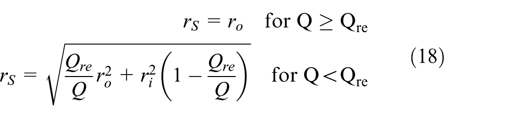
where Q is the input flow rate, and Qre is the required input flow rate. 14
Oil pump loss
The oil pump supplies the oil flow to the transmission components through the valve body. The oil pump in the target HMT is installed directly to the engine shaft (Figure 1). The regulator valve maintains a constant line pressure at 20 bar. The oil pump torque loss is determined as follows

where TP_loss is the oil pump torque loss, DP is the displacement, and P l is the line pressure. The mechanical efficiency of the oil pump (ηmech) varies with the pump speed, pressure, and temperature. In this study, experimental data from the manufacturing company were used.
Network analysis and sub-shift schedule
The efficiency of the target HMT changes depending on the speed, torque, and the HSU stroke (ist). In addition, the direction and magnitude of the power flow are changed by ist. To investigate the HMT efficiency considering the component losses, a network analysis was performed. In the network analysis, the connection relationships between the transmission components were configured as a network, and the speed, torque, and power of the HMT system were analyzed.21–24
Figure 5 shows the network model of the HMT when the second gear is engaged. Numbers 1–26 are the torque nodes, which are the same as the shaft nodes, and numbers (1)–(14) are the speed nodes. S3 and C3, between (13) and (14), denote the sun gear and carrier of the single-pinion planetary gear, respectively, which acts as the final reduction gear. When the sub-shift second gear is engaged, the carrier is not connected. Using the network model (Figure 5), the torque and the speed matrices are obtained as


where [MT] and [Mω] denote the torque and the speed matrices, respectively;

Network model of the HMT (second gear engaged).
Using the boundary vectors (

where the superscript n is the number of the shaft.
The torque and speed matrices, as well as the boundary vectors in equations (20)–(21), are modified by the amount of loss. Using modified matrices and vectors, network analyses are conducted repeatedly until the torque and speed error between the previous and current stages converse within an allowable range.
Figure 6 shows the network analysis results of the HMT efficiency in the presence or absence of mechanical losses for the sub-shift gear when the engine torque Te is 200 N m, and the engine speed ωe is 1600 r/min. When the mechanical losses are not included, the HMT efficiency of each sub-shift gear increases with the vehicle speed to 100% and then decreases. The point where the mechanical efficiency shows 100% is called the “mechanical point” (MP) because the power from the engine is transmitted only through the mechanical path without flowing through the hydraulic path. As shown in Figure 6, the HMT efficiency decreases rapidly when it departs from the MP. This is because the HSU loss increases due to the relatively lower efficiency of the hydraulic path as the power ratio of the hydraulic path to the engine input power increases. When the mechanical losses are included, the HMT efficiency drops by 14%–28% at the MP depending on the sub-shift gear. It is also noted that the reduction in the HMT efficiency increases as the vehicle speed increases. This is because the mechanical losses increase with the vehicle speed.
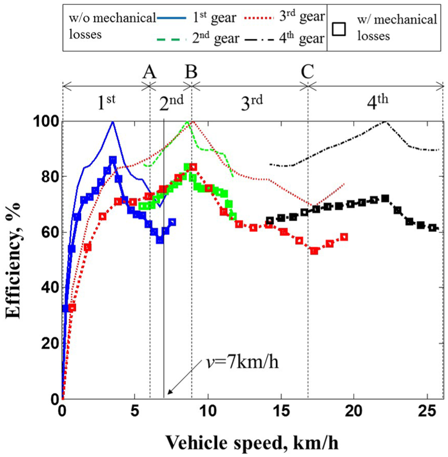
Network analysis results of the HMT efficiency in the presence or absence of mechanical losses for sub-shift gear (Te = 200 N m, ωe = 1600 r/min).
“A” (6.3 km/h), “B” (9 km/h), and “C” (16.3 km/h) in Figure 6 are the vehicle speeds where the sub-shift can be performed, in other words, where the speeds of the sub-shift clutches are synchronized. Each sub-shift can be performed at A (1 ↔ 2 sub-shift), B (2 ↔3 sub-shift), and C (3 ↔ 4 sub-shift). When the vehicle speed is 7 km/h, the HMT efficiency of the third sub-shift gear is the highest. However, only the second sub-shift gear can be used at v = 7 km/h because the sub-shift to the third gear is impossible in the region A-B in the existing sub-shift control algorithm.
The HMT losses are compared for the second and third sub-shift gears at v = 7 km/h in Figure 7. It is seen that the total HMT loss of the third gear is less than that of the second gear, of which the third gear provides a higher efficiency compared to that of the second gear at v = 7 km/h, as shown in Figure 6. It is noted that the HSU loss of the third gear and the gear losses are less than those of the second sub-shift gear. This is because the power transmitting through the HSU in the third sub-shift gear is less than that of the second sub-shift gear.
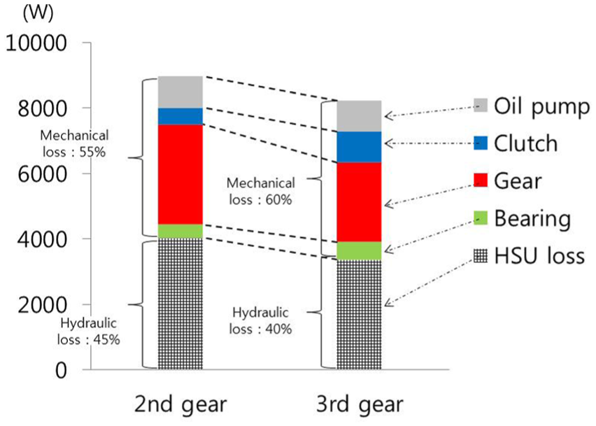
Comparison of HMT losses for the second and third sub-shift gears (Te = 200 N m, ωe = 1600 r/min, ν = 7 km/h).
The validity of the HMT loss models developed in this study was evaluated by experiment. In the experiment, since it is only possible to measure the total HMT system efficiency instead of the loss of each component, the HMT efficiency was measured using the test bench in Figure 8 and was then compared with the network analysis results, which consider the loss models. The test was performed at an engine speed of 1600 r/min and a dynamo load torque of 150 N m for the first sub-shift gear.

Test bench of the HMT.
Figure 9 shows a comparison of the HMT efficiency between the test and network analysis. It is seen that the efficiency of the network analysis agreed well with the test results for vehicle speed. The mechanical point can be found at v = 3.5 km/h for the first sub-shift gear, where the HMT has the highest efficiency in the test and network analysis. The gap between the observed efficiency and an efficiency of 100% at the mechanical point is due to the mechanical losses.
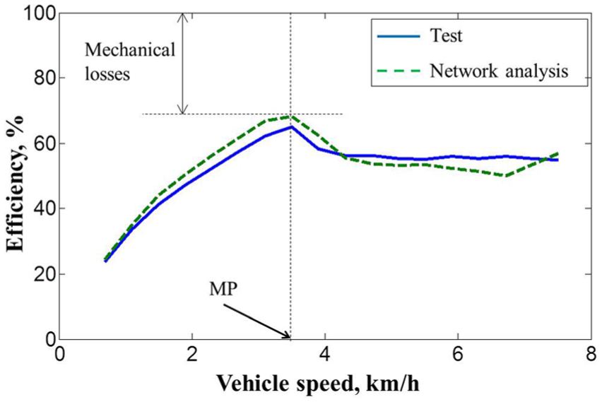
Comparison of the HMT efficiency between test and network analysis at the first sub-shift gear.
Using the network analysis, the HMT efficiency can be obtained for various engine speeds, engine torques, and vehicle speeds, and the sub-shift gear that provides the highest HMT efficiency for the given wheel torque and vehicle speed can be selected to construct the sub-shift schedule. In Figure 10, the sub-shift schedule developed in this study is shown and compared with the existing sub-shift schedule when the engine speed is 1600 r/min. As shown in Figure 10, in the existing sub-shift schedule, the sub-shift is performed according to the vehicle speed regardless of the wheel torque because the sub-shift can be carried out only when the speeds of the on-coming and off-going clutch are synchronized. On the other hand, in the sub-shift schedule proposed in this study, the sub-shift gear is selected according to the vehicle speed and the demanded wheel torque. It is also noted that for the same vehicle speed, that is, the same speed ratio, a different sub-shift gear is selected depending on the wheel torque. For example, at point P where the wheel torque is 14,000 N m and the vehicle speed v is 7 km/h, the second sub-shift gear is used in the existing sub-shift control. However, it is seen that the third sub-shift gear has better HMT efficiency in the proposed sub-shift schedule. When the vehicle speed is low (v < 4 km/h) or high (v > 20 km/h), only the first sub-shift gear or the fourth sub-shift gear can be used regardless of the HMT efficiency because of the sub-shift gear range limitation.

Proposed sub-shift schedule at ωe = 1600 r/min.
Sub-shift control algorithm without clutch speed synchronization
As shown in Figure 10, to apply the new sub-shift schedule proposed in this study, the sub-shift needs to be carried out at a vehicle speed (speed ratio) where the clutch speeds are not synchronized. To perform the sub-shift without the clutch speed synchronization, the following problems should be solved:
Driveshaft torque variation: the driveshaft torque TDS will experience torque variation due to the transient terms in equations (7) and (8) such as the engine torque variation, HSU stroke differential, and the engine speed differential. In particular, the engine speed differential, which has a negative value during the upshift, causes the driveshaft torque to increase in the positive direction.
HSU stroke change: the HSU stroke should be changed to satisfy the given speed ratio.
Forward clutch pressure control
As shown in Figure 1, the target HMT has the forward clutch, which is controlled by a proportional valve. In the target HMT system, two types of hydraulic valves are used to control the clutch pressure: (1) an on/off-type valve for the sub-shift clutches and (2) a proportional valve for the forward and reverse clutch. The on/off-type valve has the advantage of a relatively low cost; however, precise pressure control is impossible. In contrast, the proportional valve can control the pressure in a proportional manner.
In this study, the driveshaft torque control algorithm was presented by limiting the transfer torque of the forward clutch. In the target tractor, the forward clutch pressure is maintained as a lock-up pressure, which is quite higher than the clutch pressure, to transmit the required torque. Since the magnitude of the forward clutch torque TFWD is proportional to the clutch pressure, the forward clutch pressure is controlled to reduce the torque variation while maintaining the demanded driveshaft torque TDS_dmd during the sub-shift.
Since the PTO workings require a constant vehicle speed, 25 the forward clutch pressure is controlled only to transmit the same torque during the sub-shift. The forward clutch pressure to transmit TDS can be obtained as

where TDS_dmd is the demanded driveshaft torque before the sub-shift, µ is the friction coefficient, R is the radius, A is the area, k is the stiffness of the return spring, and x is the displacement. Subscripts eff and pis indicate the effective radius of the clutch disk and the clutch piston, respectively. The demanded driveshaft torque TDS_dmd for each sub-shift gear is determined from the HMT gear ratio and the engine torque.
Figure 11 shows a schematic of the forward clutch pressure control algorithm proposed in this study. When the sub-shift signal is applied, PFWD_cmd decreases in a stepwise manner to PFWD_dmd and is maintained until the forward clutch speeds are synchronized. At that point, PFWD_cmd increases up to the lock-up pressure. Even if the forward clutch pressure PFWD decreases to PFWD_dmd, which can transmit the demanded driveshaft torque, the clutch slip occurs because the driveshaft torque fluctuates around the demanded torque due to the effect of the rotational inertias connected to the driveshaft.

Schematic of the forward clutch pressure control.
HSU stroke control
To perform the sub-shift without the speed synchronization, the HSU stroke should be changed to satisfy the given engine and vehicle speeds, in other words, the given speed ratio, SR. When the tractor works using the PTO, in general, the engine and vehicle speeds need to be maintained at a constant value. 25 The HSU stroke ist, which maintains the demanded engine speed for the given vehicle speed, can be obtained. The speed ratio SR for the second and third sub-shift gears is derived using the HSU stroke as follows


The relationship between the speed ratio SR and HSU stroke ist for the first and fourth sub-shift gears can be obtained in a similar way.
Simulation and discussion
The performance of the sub-shift control algorithm without the sub-shift clutch speed synchronization was evaluated. To investigate the dynamic characteristics of the target tractor with HMT, a performance simulator was developed based on the dynamic model of the tractor using AMESim. In Figure 12, the performance simulator developed in this study is shown. The vehicle specifications used in the simulator are listed in Table 1. The controller, which determines the command values of the engine and the HMT, was developed using MATLAB/Simulink.

Performance simulator of the HMT tractor.
Specifications used in the simulator.
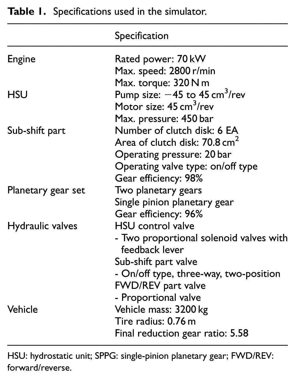
HSU: hydrostatic unit; SPPG: single-pinion planetary gear; FWD/REV: forward/reverse.
The simulation to evaluate the sub-shift performance without the clutch speed synchronization was carried out at point P in Figure 10 from the second to third gear. When the HMT is operating at P, in the existing sub-shift control, the second sub-shift gear should be used according to the shift schedule, which is determined only by the vehicle speed (speed ratio). However, in the new sub-shift schedule, the third sub-shift gear needs to be selected to achieve the improved HMT efficiency.
To perform the sub-shift from the second to third gear, the sub-shift control algorithm without the clutch speed synchronization was applied using the forward clutch pressure control and HSU stroke control proposed in this study.
The forward clutch pressure PFWD_dmd was determined from equation (23) using the driveshaft torque TDS_dmd, which can be calculated using the engine torque, the speed ratio, and the HMT efficiency. When obtaining the driveshaft torque, the inertial torque of the rotational inertias can be neglected, since the vehicle speed is maintained at a nearly constant value. The HSU stroke, which satisfies the HMT operation at point P of the third sub-shift gear, can be determined from equation (25) as follows

Figure 13 shows the simulation results for the second → third sub-shift by the proposed sub-shift control algorithm without clutch speed synchronization. Before the sub-shift, the engine speed was maintained at ωe = 1600 r/min, and the vehicle speed v was 7 km/h. When the sub-shift signal was applied at t = 0.2 s, the HSU stroke command (ist_cmd) obtained from equation (26) was applied in a stepwise manner (a). The actual HSU stroke followed the command stroke, exhibiting the second-order dynamic characteristics in equation (9).
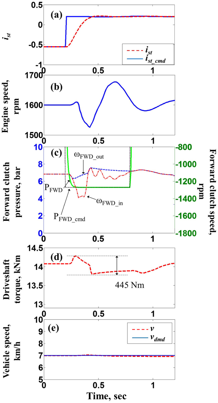
Simulation results for second → third sub-shift. i st : HSU stroke; i st_cmd : HSU stroke command; ω FWD_out : forward clutch output speed; ω FWD_in : forward clutch input speed; P FWD : forward clutch pressure; P FWD_cmd : forward clutch pressure command; V: vehicle speed; V dmd : demanded vehicle speed.
When the sub-shift signal was applied, PFWD_cmd decreased in a stepwise manner to PFWD_dmd and was maintained until the forward clutch speeds were synchronized. At that point, PFWD_cmd increased to the lock-up pressure. Even if the forward clutch pressure PFWD decreased to PFWD_dmd, which can transmit the demanded driveshaft torque, the clutch slip occurred because the driveshaft torque fluctuated around the demanded torque due to the inertial torque of the rotational inertias connected to the driveshaft. As shown in Figure 13(e), the vehicle speed was almost maintained at the demanded speed. The peak-to-peak of the driveshaft torque was obtained as 445 N m.
Unlike conventional transmissions in automobiles, it is difficult to evaluate the shift quality of the tractor since the shift quality is affected greatly by the type of workings, the type of transmission, and the class of tractor. 26 It was reported that the maximum peak-to-peak of the driveshaft torque is 10,000 N m in a 62.5-kW class tractor equipped with power shift transmission when driving on a flat road. 27 Compared with the peak-to-peak torque of the power shift transmission, the 445 N m of the target HMT tractor by the proposed sub-shift control is considered to be in the acceptable range.
Experimental results and discussion
To investigate the performance of the proposed sub-shift control algorithm, the experiments were performed using the test bench in Figure 8. In the test bench, since the dynamo motor was connected to the HMT output shaft, the HMT output torque was measured instead of the driveshaft torque.
In Figure 14, the experimental results are shown. In the experiment, the second → third sub-shift was carried out by the proposed sub-shift control algorithm without clutch speed synchronization. When the sub-shift signal was applied at t = 0.1 s, the forward clutch pressure PFWD (d) decreased in a stepwise manner, maintained 2.1 bar for 0.6 s, and increased again. The HSU stroke ist increased from ist = −0.55 to ist = 0.2 to meet the same speed ratio before and after the sub-shift. Since the speed sensor for the sub-shift shaft could not be installed in the test bench, the time when the speeds of the input and output clutches become equal could not be measured. Therefore, in the experiment, the duration time that was obtained from the simulation was used.
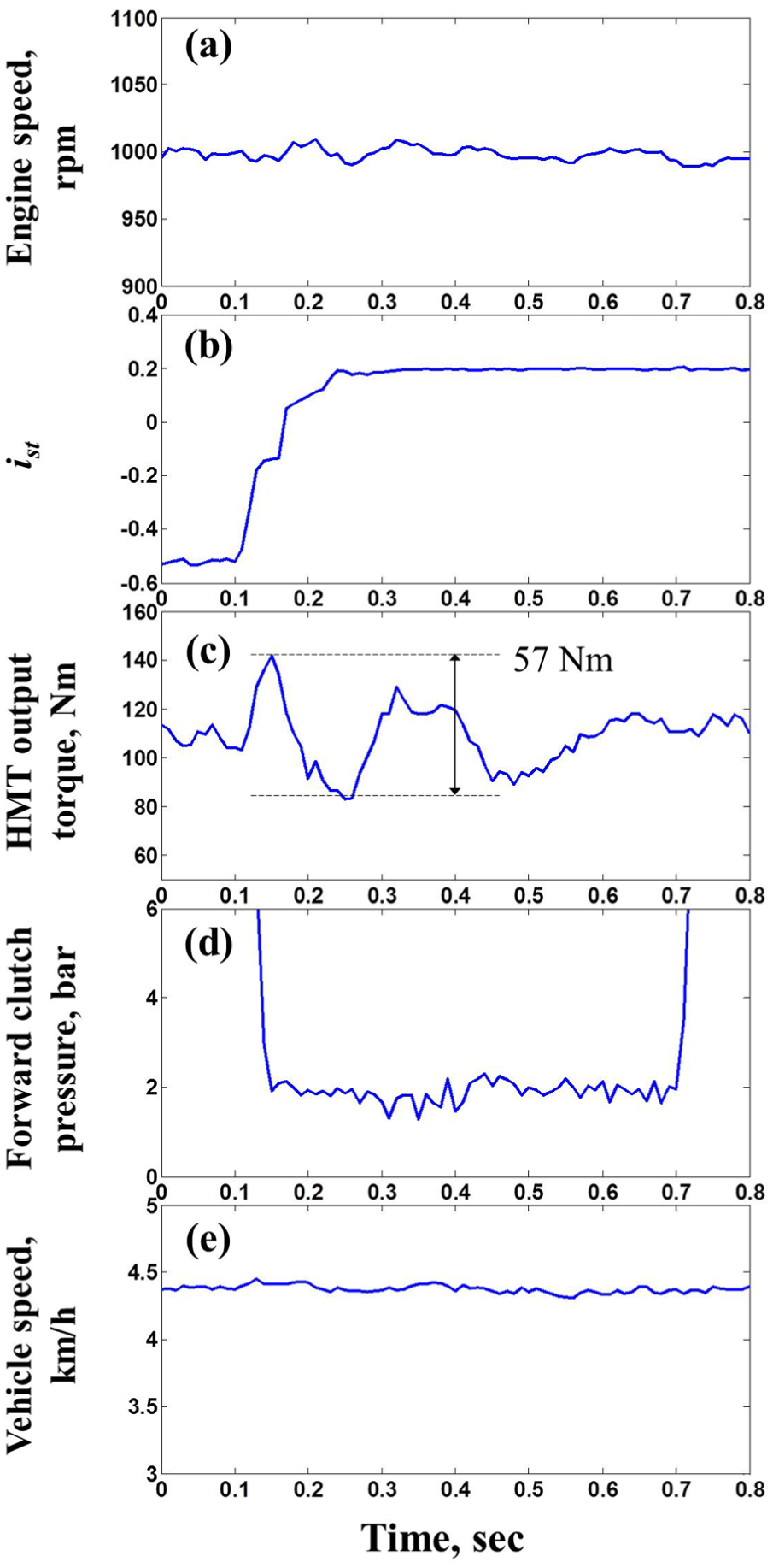
Experimental results for second → third sub-shift without clutch speed synchronization. i st : HSU stroke.
The peak-to-peak torque in the experimental results (Figure 14) was 57 N m. Unlike the simulation, this peak-to-peak torque was measured at the HMT output shaft, not at the driveshaft because the driveshaft was not installed in the proto-type HMT used in the experiment. Considering the final reduction gear ratio between the output shaft and the driveshaft, the HMT output shaft torque turned out to be 1550 N m of the driveshaft torque variation. Even if this value is higher than the simulation result of 445 N m, it is considered to be acceptable compared with the experimental results for a flat road, 10,000 N m. 27 The reason why the experimental result of the driveshaft is higher than that of the simulation result is that the driveshaft and tire were not installed in the proto-type HMT used in the experiment. If the stiffness effect of the driveshaft and tire was included, the peak-to-peak torque variation is expected to be reduced.
It was also seen that the engine speed (a) and vehicle speed (e) were maintained at almost constant values, which is required for PTO workings. It was found from the experimental results that the sub-shift control algorithm without the clutch speed synchronization proposed in this study can provide a satisfactory sub-shift, while maintaining constant engine and vehicle speeds.
Conclusion
A new sub-shift schedule that provides improved system efficiency was proposed for an HMT, which consists of an HSU, planetary gear set, and four sub-shift gears. In addition, to apply the sub-shift schedule, a sub-shift control algorithm without clutch speed synchronization was developed.
To construct the sub-shift schedule, a network analysis was performed by considering the HSU loss and mechanical component losses. For the HSU loss, an HSU efficiency map was used from the experiment. To obtain the mechanical component losses, individual models were constructed for the bearing loss, gear churning loss, clutch drag loss, and oil pump loss based on the mathematical governing equations and experiments.
Using the network analysis results, a new sub-shift schedule was proposed for the demanded wheel torque and vehicle speed. Unlike the existing sub-shift schedule, which selects the gear ratio based only on the vehicle speed, the new sub-shift schedule selects the sub-shift gear according to the demanded wheel torque and vehicle speed. Since the sub-shift can only be performed at a speed ratio where the clutch speeds are synchronized in the existing sub-shift control, a sub-shift control algorithm without clutch speed synchronization was proposed to apply the new sub-shift schedule.
First, an HSU stroke control was developed to maintain the demanded engine speed for the given vehicle speed. The HSU stroke at the target sub-shift gear ratio was determined from the lever relationship for each sub-shift gear. Next, the forward clutch pressure control was proposed, which reduces the torque variation during the sub-shift while transmitting the demanded driveshaft torque. The forward clutch pressure was decreased in a stepwise manner to a pressure enough to transmit the demanded driveshaft torque and was maintained until the forward clutch speeds were synchronized. This pressure drop caused a slip between the clutch plates, which prevented excessive torque fluctuation. After the forward clutch speed synchronization, the clutch pressure was increased to the lock-up pressure.
The performance of the sub-shift control algorithm without the clutch speed synchronization was evaluated by the simulation and experiment. It was found from the simulation and experimental results that the sub-shift can achieve acceptable peak-to-peak torque variation in the driveshaft. It is expected that the sub-shift schedule and the sub-shift control algorithm without the clutch speed synchronization can provide improved fuel economy while maintaining the demanded speed ratio.
Footnotes
Academic Editor: Francesco Massi
Declaration of conflicting interests
The author(s) declared no potential conflicts of interest with respect to the research, authorship, and/or publication of this article.
Funding
The author(s) received no financial support for the research, authorship, and/or publication of this article.