
Abstract
Surface acoustic wave sensors offer overwhelming advantages over other potentially competitive sensing technologies in rotating mechanical structures for their wireless and passive capability. Nevertheless, the challenges of using these sensors have not been adequately addressed. Radio frequency signal of surface acoustic wave sensors acts as not only the role of data transmission but also the role of energy supply during the sensing system working process. Thus, the performance of surface acoustic wave sensors when they are used to monitor rotating spindles should be investigated due to the harsh metallic environments for radio propagation in machine tool. This article aims to experimentally study the performance of surface acoustic wave sensors on both rotating spindle with Computer Numerical Control machine tool and self-developed spindle apparatus. The measurement study is performed using a temperature surface acoustic wave sensor working in the Industrial Scientific and Medical (ISM) band (433.05–434.79 MHz). Experimental results have shown that transmission and measurement characteristics were closely depended on the surface acoustic wave sensor installation location and rotation speeds. The conclusions will directly guide the sensor location optimization, power setting, errors avoidance, or correction in the future work.
Introduction
Advanced sensor system design and their integration into machine tools enable improved understanding of the process conditions and facilitate optimization and control of the part quality.1,2 Spindle units in machine tools, built within totally closed metallic shells, are among those hard-to-reach structures having crucial monitoring importance. 3 Seeking and establishing novel monitoring methods in machine tools are significant. Although using wireless sensors is a good solution for condition monitoring, the sensors’ power supply is another key factor to be considered, especially for the spindle unit in an enclosure structure. Free from power and communication cables, surface acoustic wave (SAW) sensors are promising candidates for machine tool condition monitoring due to their small size, passive operation, wireless installation, free maintenance, and ability to withstand extreme conditions. 4 Traditionally, since their first emergence in the 1970s, SAW sensors have gained substantial attentions for signal processing in industrial and domestic applications, such as the strain, temperature, and pressure.5,6 Successful applications of SAW sensors have been reported in recent research reports, such as in-car tire pressure monitoring system, 7 monitoring the temperature of the refractory lining of a metallurgical vessel, 8 high-speed high-voltage motors temperature measurement, 9 torque measurement in kinetic energy recovery system, 10 monitoring of switchgear temperature, 11 working as gas sensors with an adequately selected sensor structures, 12 and monitoring the tool condition.13,14
Spindle units are common rotating mechanical structures mostly found in metallic enclosures that are harsh for radio communication due to rich stationary and moving structures. Usually, multipath propagation, delay spread, multipath fading, and Doppler effect are important factors causing transmission errors of wireless sensors in manufacturing environment. 15 Although the data transmission characterization of wireless sensors on rotating mechanical structures has been systematically investigated in literature,15–17 and the performance of SAW sensors on such structures is still in doubt due to its distinctive principle of operation. That is, the radio frequency (RF) signal acts as not only the role of data transmission but also the role of energy supply during the SAW sensing system working process. 18 Therefore, the frequency pulling effect due to the metallic environment on the antenna impedance and metallic cavities forming due to conducting parts of machine tool are two significant issues of SAW sensors which may potentially induce measurement errors. Although various studies have applied SAW sensors on rotating mechanical structures for condition monitoring, a systematic study of their data transmission and measurement performance in manufacturing environments is still missing. This study is devoted to characterizing such performance of SAW sensors on a spindle in the machine tool, especially the dependency of the performance on different installation locations and rotation speeds. The results can serve as a guidance of SAW sensors in manufacturing environment monitoring applications and fundamental knowledge toward sensors’ performance optimization.
The rest of this article is organized as follows: section “Background” presents backgrounds on the operation of SAW sensors and research considerations. Section “Experimental setup” overviews the experimental setup and environments. Experimental implementations and results’ analysis are described in section “Experiments and discussions.” The article is finally concluded in section “Conclusion and future works.”
Background
Theory and principle of SAW sensors
A one-port SAW resonator sensing element is used, fabricated on a YX-cut quartz piezoelectric substrate, as illustrated in Figure 1(b), consisting of an interdigital transducer (IDT) and reflectors on both sides of the piezoelectric substrate. The SAWs are generated by the IDT and are reflected by the reflectors to form a standing wave pattern, causing resonance. The shift in the resonance frequency of the resonator generated with the varying piezoelectric plate physical characters, caused by external factors, such as the temperature, strain, and torque. 19 The required parameters can be obtained by measuring the shift of the center frequency.

Illustration of wireless passive SAW sensing system operation: (a) Interrogator unit, send out RF signal and receive sensor signals, (b) SAW sensor, receive RF signal and send out sensor signals, and (c) Server and monitor, interrogator unit setting, signal process and display.
Figure 1 illustrates the complete workflow of the interrogation procedure typically involving four main steps as follows:
Interrogator unit (Figure 1(a)) setting and RF signals transmit. The interrogator configured by the server (Figure 1(c)) originally, including the number of interrogator antennas and SAW sensors, the sampling intervals, and RF signal frequencies, and then the interrogator unit sends out RF signal (electromagnetic wave) at a specific frequency and over a given time period toward the SAW sensor.
SAW sensor (Figure 1(b)) excitation and resonance. Once the sensor antenna receives the RF signal and transmits the energy to IDT via the induction, the SAW sensor is activated and converts the received signal into a SAW, propagating on the piezoelectric substrate toward the reflectors, forming a standing wave, causing resonance.
Sensor signal form and response. The IDT receives the returned SAW which was converted into electric signals and emitted as the electromagnetic wave (sensor signals) through the sensor antenna to the interrogator unit.
Signal process and display. The interrogator antenna receives the sensor signals and transmits it to the interrogator unit. Analyzing the received sensor signals, the interrogator can track the sensor resonance frequency and after post processing, the monitor can give out the measuring results of measured parameters.
Research consideration and method
Spindle units or other rotating mechanical structures are generally located within confined enclosures, with the structures themselves and their surroundings made of metallic materials. Monitoring these structures with wireless passive SAW sensors is one of the best choices at present. But radio propagation is expected to be affected by many kinds of interference, such as reflection, diffraction, and scattering in inhomogeneous mediums, 20 which has the characteristics of complexity, randomness, and time-varying. For spindle monitoring in Computer Numerical Control (CNC) machine tool, the propagation is more complex, including path loss, multipath fading, shadow fading, 17 high rotation speeds, and pulling effect.
Path loss is caused due to the dissipation of the power radiated by the transmitter as well as effects of the propagation channel. Signal attenuation due to path loss generally occurs over very large distances, 21 and the effect of path loss is considered to be insignificant in this research.
Multipath fading occurs when the transmitted signal arrives at the receiving antenna in different paths (multipath propagation), causing time dispersion and signal attenuation. 22 It cannot be neglected in the machine tool environment considering multiple reflections of complex metallic materials.
Shadowing or shadow fading is the attenuation of radio signal strength due to the phenomena of reflection, refraction, and diffraction in the environment. It can vary widely from one area to another depending on the territories and geographical characteristics. 23 Sensors mounted on a spindle or other rotating structures locate in the shadow area most of the time, and shadowing effect is a critical consideration.
Rotation speed will decrease the electric performance of wireless sensors and causes Doppler effect. When rotating, the sensors will be applied with a large centrifugal force, and the reliability of the sensors’ hardware will decrease. As an example, the spindle radius r is 50 mm, rotation speed n is 2000 r/min, and sensor mass m is 5 g; according to the calculation formula of
Pulling effect refers to unwanted frequency change due to the metallic environment–induced parasitic impedances of the probed circuit. It will always yield frequency decrease with respect to the resonator resonance frequency 24 and induces the measurement errors, which is the core difference compared with traditional wireless sensors.
Each consideration mentioned above is a profound scientific question, and here, the research aims to experimentally investigate the performance of SAW sensors on rotating spindles based on these considerations.
Experimental setup
In order to investigate the performance of SAW sensor in a manufacturing environment, a series of experiments were designed and performed on a CNC machine tool and a self-developed spindle apparatus, respectively. The CNC machine tool represented the actual production manufacturing environment, while the self-developed spindle apparatus was embedded with SAW sensor to simulate the spindle unit.
SAW sensing system
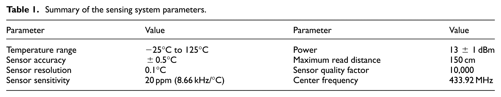
The sensing element used in the experiments was a signal-port SAW resonator which is provided by the Salisense Technology Company. 25 The system operating frequency range was from 432 to 444 MHz, which corresponds to three interrogator antennas and 18 SAW sensors at most (one interrogator antenna could read/carry out six SAW sensors at most). Considering the ISM (433.05–434.79 MHz) band, here, only one temperature sensing element was used and its center frequency was 433.92 MHz. The transmit power was 13 ± 1 dBm, and the packet inter-arrival time was 2 s. Table 1 summarized the sensing system parameters’ setting in the experiments.
Summary of the sensing system parameters.
Rotating spindle in CNC machine tool
A numerical control mold engraving and milling machine was adopted in the experiments. Figure 2 shows the machine tool exterior with the spindle in a metallic enclosure. A closer view of the spindle and the sensor is shown in Figure 2(b). The SAW sensor was fixed on the spindle with its antenna parallel to the spindle axis by a metal plate. To determine the location of the SAW sensor in quasi-static rotation, a paper-made scale with a 45° increment step to eight angular positions was attached to the spindle shell.

CNC machine tool: (a) exterior photograph and (b) spindle with SAW sensor.
The graphical representation in Figure 3 permits to know the location relationship between the interrogator antenna and the SAW sensor in more detail. The interrogator antenna was placed at six different locations, which is perpendicular to the SAW sensor antenna. The SAW sensor location could be adjusted in the range of 0–30 mm, which was rotated with spindle around its axis in a 45° increment step.

Relationship between interrogator antenna and SAW sensor locations.
Self-developed spindle apparatus
For high-speed rotating experiments, a self-developed spindle apparatus has been set up. Figure 4 illustrates the components of the spindle apparatus, including the spindle model, motor driver, and the SAW sensing system. A SAW sensing element was embedded in the spindle and connected to the sensor antenna by coaxial cable, as can be seen in Figure 4(b). The diameter of the spindle was 60 mm, and the rotating speed can be adjusted continuously in the range of 0–3000 r/min. For safety, the maximum rotating speed was chosen as 2000 r/min in this article. Besides, a data acquisition system with four PT100-type temperature sensors was used as the criterion-referenced assessment, and a vibration isolation platform was used in order to exclude the external vibration.

Self-developed spindle apparatus: (a) setup scheme and (b) sensor installation.
Experiments and discussions
Experiments on CNC machine tool
Three experiments were carried out on the CNC machine tool: (1) performance evaluation of SAW sensor around the spindle with interrogator antenna at six different locations, including power indicator, temperature measurement, and packets loss; (2) characteristic evaluation of SAW sensor with five different distances between the spindle and the sensor, including power indicator and temperature measurement; (3) power indicator distributions with different distances between the spindle and the sensor antenna at different rotating speeds (≤300 r/min). In the first experiment, the distance between SAW sensor and spindle surface was 20 mm, and the sensor calibration temperature equaled to the ambient temperature (26.1°C). In the following two experiments, the interrogator antenna was fixed at 5# location. In each experiment, the testing time lasted 60 s in every angular position; that is, 30 packets could be obtained at each position in theory.
Figure 5 shows the average power of interrogator unit–received packets and temperature measurement with six different interrogator antenna locations. Both the average power and temperature were more flat in the range of 0°–180° compared with 225°–315°. The average power at the positions of 1# and 4# has a similar change trend, but the average temperature was not in agreement. Same results could be obtained with groups of (2#, 5#) and (3#, 6#). Temperature measurement was failed at 315° angular position at 1# location, 270° at 2#, and 225° at 3#. Results suggest that changing the interrogator antenna location will influence the temperature error occurring position.

Results with different antenna locations: (a) average power of interrogator unit–received packets and (b) average temperature.
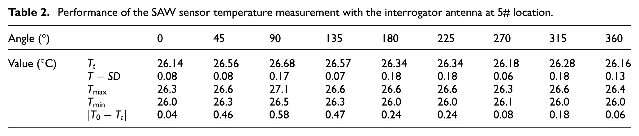
Figure 6 analyzes the standard deviation of temperature measurement and the absolute value of difference between the testing temperature and actual temperature. The standard deviations were less than 0.2°C except positions of 315° at 1#, 270° at 2#, and 225° at 3#. However, the temperature absolute difference value seemed to be related to angular positions. Big errors occurred in a specific region. Taken 5# position as an example, Table 2 calculated the average temperature

Analysis of temperature measurement: (a) standard deviation and (b) absolute difference.
Performance of the SAW sensor temperature measurement with the interrogator antenna at 5# location.
The graphical representation in Figure 7 permits to know the packets receiving during the temperature measurement with six different interrogator antenna locations. Packets loss appeared at only three angular positions (315° at 1#, 270° at 2#, and 225° at 3#) where the loss rates were 46%, 93%, and 53%, respectively. Analyzing the packets received at these positions carefully, there were 2 error packets (2/16) at position 1#, 1 (1/2) at 2#, and 14 (14/14) at 3#. Interestingly, these three positions had a strong line of sight (LOS), but packets loss occurred in these areas. The results indicate that the inappropriate interrogator antenna installation location not only causes packets loss but also induces measurement errors.

Packets receiving with interrogator antenna at different locations.
Based on above experiments, the interrogator antenna at 5# position was regarded as the optimal installation location. Performance of the SAW sensor with different distances (0, 5, 10, 15, and 20 mm) between the spindle and the SAW sensor antenna experiments were carried out, while the interrogator antenna was fixed at position 5#. Figure 8 shows the average power of interrogator unit–received packets and temperature for five different distances between the SAW sensor antenna and spindle surface. The sensor location influenced the average power, and the power increased with the increase in distance except the distance 0 mm. But it would not increase when the distance exceeded 20 mm. Actually, the distances of 25 and 30 mm were also carried out and not gave out in the figure for they were similar to the distance of 20 mm. The average temperature changed dramatically at different distances, as seen in Figure 8(b). Although the average power was similar at 5 and 10 mm distances, the temperatures had a big difference. Meanwhile, packets receiving were also discussed in Figure 9. Packets loss appeared at the distances of 5 and 10 mm, where the loss rates were 70% and 33%, respectively. This experiment indicates that the SAW sensor installation location has a significant influence on its accuracy and reliability in manufacturing environment. The performance of SAW sensor is more highly susceptible to the environment compared with traditional wireless sensors.

Results with five different distances: (a) average power of interrogator unit received packets and (b) average temperature.
Packets receiving with SAW sensor at different distances.
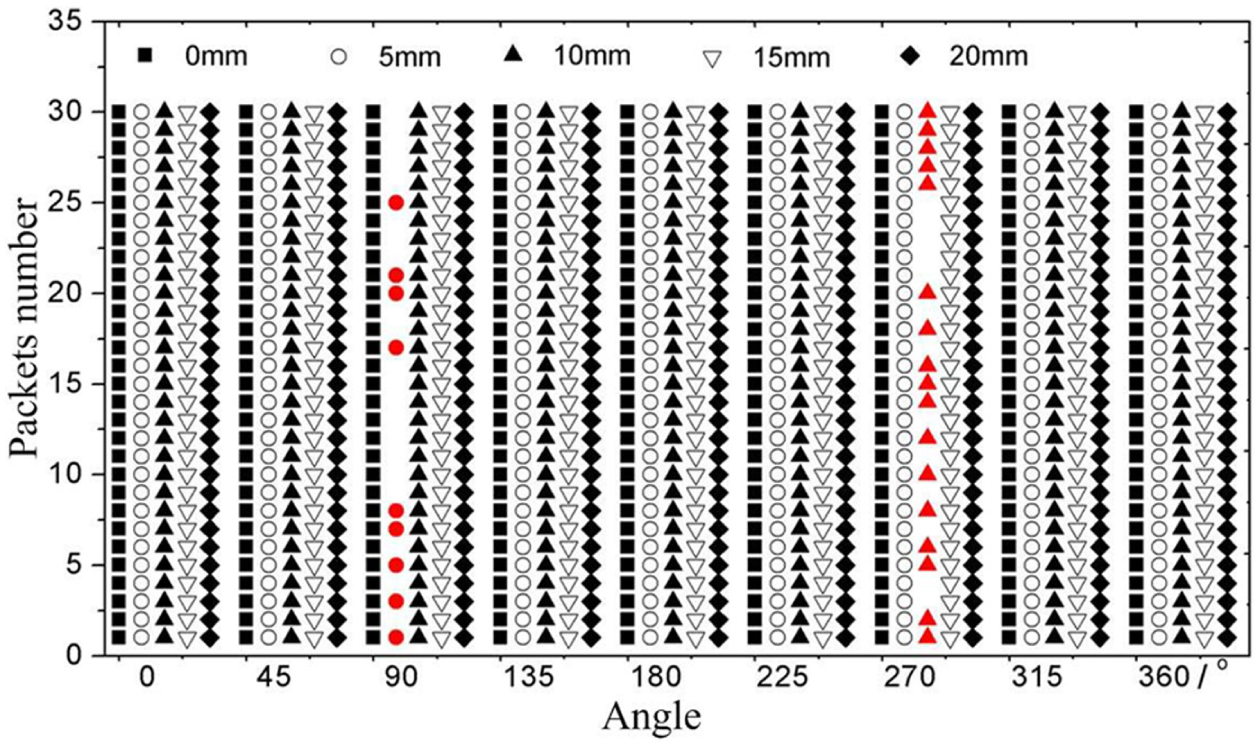
The rotating experiment to evaluate the power distribution and packets receiving with different distances between the spindle and SAW sensor was carried out on a CNC machine tool. For safety, 300 r/min was chosen as the maximum rotating speed in the experiment. Figure 10 summarizes the average power distribution at five distances (5, 10, 20, 25, and 30 mm) with different rotating speeds (10, 100, 150, 200, 250, and 300 r/min) for 5 min continuous operation, respectively, and shows that the proportion of high-power indicator increased with the increase in speed. Figure 11 demonstrates the result of packets receiving at different speeds. Packets loss decreased when the distance and rotating speed increased, except at the speed of 10 r/min and the distance of 5 mm. No packets loss appeared when the distance was 30 mm in all speeds. Results of this experiment indicate that the power distribution and packets loss are related to the SAW sensor installation location and the spindle rotating speeds.
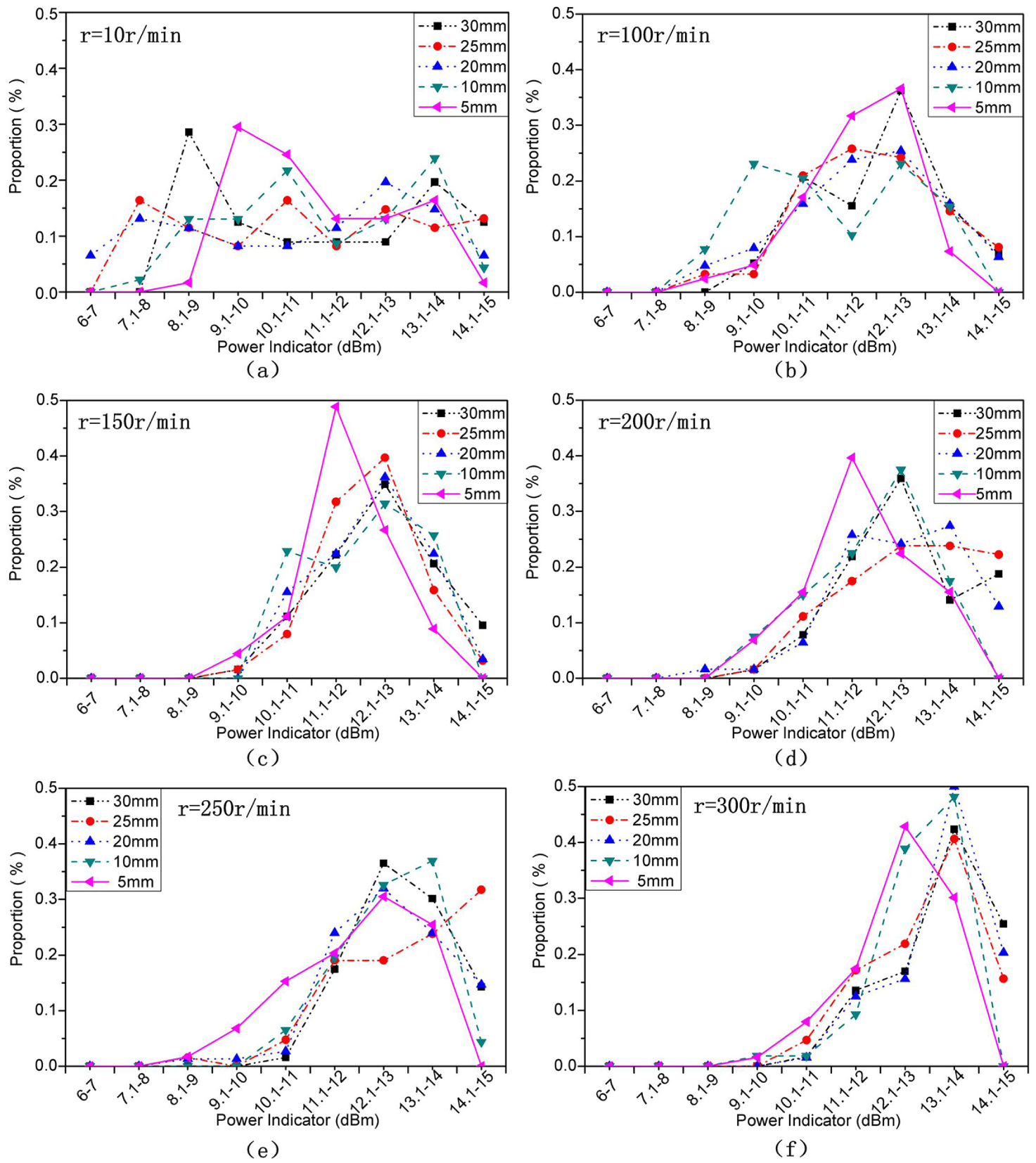
Power distribution at different distances with different rotating speeds: (a) rotating speed of 10 r/min, (b) rotating speed of 100 r/min, (c) rotating speed of 150 r/min, (d) rotating speed of 200 r/min, (e) rotating speed of 250 r/min, and (f) rotating speed of 300 r/min.

Packets receiving at different distances with different rotating speeds.
Experiments on self-developed spindle apparatus
Temperature rising and cooling experiments were carried out at different rotating speeds on the self-developed spindle apparatus. Figure 12 shows the temperature rising curve of spindle acquired by the SAW sensor and PT100 sensors at 1500 r/min speed for 120 min continuous operation and indicates that 5°C difference existed between direct methods (SAW sensor) and indirect methods (PT100 sensors). Although the SAW sensor could monitor the spindle temperature directly, big fluctuations appeared occasionally.

Temperature rise of spindle at 1500 r/min rotating speed.
Results in Figure 13 were taken when the spindle operating at 500, 1000, and 2000 r/min speeds for 120 min rotation and 180 min stationary. Fluctuations appeared in rotation stages, while no fluctuations existed in stationary stages. What is more, numbers of fluctuations increased with the increase in rotating speeds.
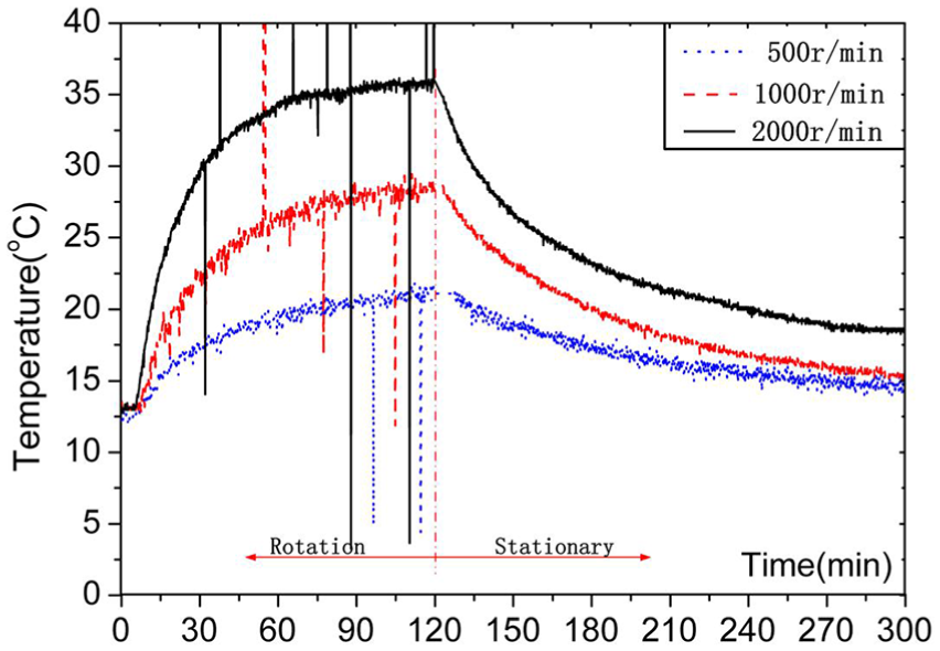
Temperature rising and cooling of the spindle at different rotating speeds.
Figure 14 illustrates the average power and their standard deviations of four rotating speeds. With increase in rotating speeds, the average power increased slightly and it was consistent with the conclusion derived from Figure 11.
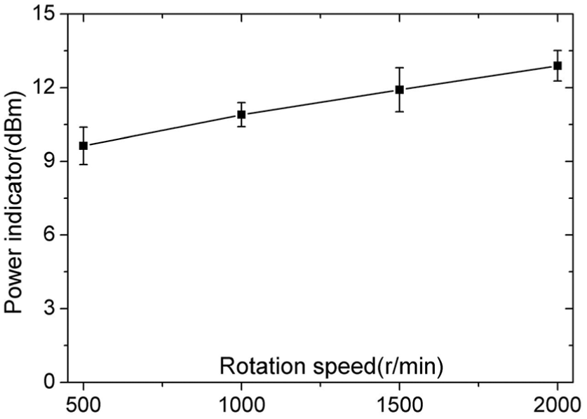
Average power at different rotating speeds.
Figure 15 summarizes the SAW sensor packets receiving and loss at four different rotating speeds. Numbers of received packets increased with the increase in rotating speeds. Some error packets existed among the received packets, 2 error packets in 500 r/min, 5 in 1000 r/min, 8 in 1500 r/min, and 10 in 2000 r/min rotating speeds. Although the packets loss decreased, the packets error rate increased with the increase in speeds. The possible reason of inducing error packets may be the decrease in sensors’ hardware stability, which was caused by a large centrifugal force due to high rotating speeds.
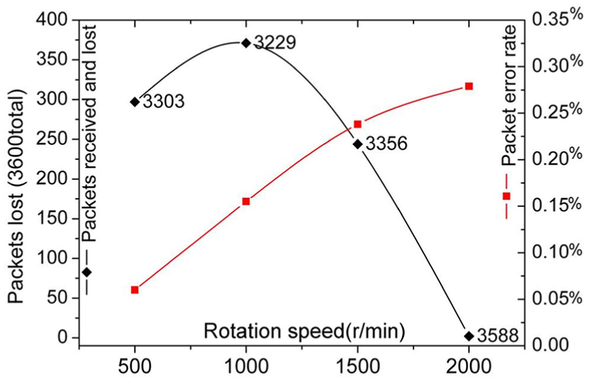
Packets receiving and loss at different rotating speeds.
Discussions
From all the experimental results, it can be found that transmission and measurement errors had appeared. Small changes in interrogator antenna and SAW sensor positions resulted in large changes in the average power indicator and temperature (Figures 5–7). Changing the interrogator antenna position in the six locations caused small changes in the transmission path but resulted in large changes in the average power and temperature, and the packets loss and errors had a regional distribution characteristic. As shown in Figures 5 and 7, both packets loss and big temperature errors appeared in the range of 225°–315° at specific interrogator antenna locations. This indicated that path loss had an insignificant influence on the transmission performance, while the multipath or shadowing fading had significant influences. In the small and confined enclosure, radio signals are subject to multiple reflections by the metallic parts and enclosure, creating more signal paths between the interrogator antenna and the SAW sensor.
Large changes in the average power and temperature occurred in all angular positions when changing the sensor antenna installation location (Figures 8 and 9). As shown in Figure 8, there is a minimum installation distance for the sensor antenna, approximately 20 mm in this research, since the measured temperature values varied when the distance was below 20 mm but not changed when the distance exceeded 20 mm. Impossible measurement occurred at specific angular positions of two sensor antenna installation locations (5 and 10 mm), as shown in Figure 9. Large measurement errors occurred due to the pulling effect caused by changes of the sensor circuit electrical properties. Parasitic impedances due to the metallic environment and change of angular positions induced an impedance change of the whole sensing system (the SAW sensor equivalent circuit model was a series inductors and capacitors) which led to the resonance frequency changing. Besides, conducting materials around the SAW sensor and the metallic enclosure formed some metallic cavities; measurement errors appeared when their quality factors overwhelmed that of sensor resonators, which even made the measurement impossible. What is more, the returned incoming echo and the coming wave would occur resonance since any passive reflector would return the incoming echo with no delay, this also made the measurement impossible if the resonance frequency duration exceeded that of the sensor response.
The average power increased slightly with the increase in rotation speeds both in the CNC machine tool and self-developed spindle apparatus, while the packets loss decreased and packets with error increased (Figures 10–15). This indicated that packets loss could be reduced by improving the transmission power, but packets with error appeared to no avail. Actually, there was a gray area, in which the observed packets typically fluctuated vibrantly when the received signal power indicator fell within a specific power area near the radio sensitivity. When the received power indicator was above 9 dBm, the packets loss is fairly low down to 0, and the packets are completely lost when the received power was below 6 dBm in our previous related research. From Figure 11, we also concluded that there is a minimum distance between the sensor antenna and spindle to ensure the transmission power in terms of packets loss, and the minimum distance was about 20 mm in this research. Electromagnetic noise due to the spindle apparatus and surroundings, hardware stability due to the high rotation speed–induced large centrifugal force, and vibration might be the main reasons causing big fluctuations, as shown in Figures 12 and 13. Because when the spindle is stationary, there are no big fluctuations. Besides, the times of the SAW sensor seeing the interrogator antenna (LOS) increased with the increase in rotation speeds per unit time which could help understand why packets loss decreased.
Conclusion and future works
As the first attempt to systematically investigate the transmission and measurement performance of SAW sensor in manufacturing environment, a series of experiments were executed on a CNC machine tool and the self-developed spindle apparatus. Some interesting conclusions are given out as follows. (1) Interrogator antenna installation location has a significant influence on SAW sensors performance. Changing the antenna installation location will change error packets’ occurring positions and even avoid packets loss. Seeking optimal installation location will improve the performance of the sensing system greatly. (2) SAW sensor–mounted location also makes a significant impact on its characteristics. There is an optimal distance between the SAW sensor and spindle realizing the best transmission and measurement capability. (3) Rotation speed has an important implication for power distribution and packets receiving. With the increase in rotating speeds, power will become more concentrated on higher value region and packets loss will decrease slightly. Nevertheless, the proportion of error packets among received packets increases with the increase in spindle speeds. (4) SAW sensor could monitor the temperature inside the spindle more precisely for its flexible installation mode, but measures should be taken to overcome big temperature fluctuations due to the high rotation speeds.
In future work, theoretical researches will be executed to explain the experimental results. Methods to improve the transmission and measurement performance of SAW sensors in machine tool spindle monitoring applications will be also discussed based on these research conclusions.
Footnotes
Academic Editor: Duc T Pham
Declaration of conflicting interests
The author(s) declared no potential conflicts of interest with respect to the research, authorship, and/or publication of this article.
Funding
The author(s) disclosed receipt of the following financial support for the research, authorship, and/or publication of this article: This paper was sponsored by the Science Fund for Creative Research Groups of the National Natural Science Foundation of China (no. 51521064), Zhejiang Province Public Projects of China (no. 2016C31036), and the Fundamental Research Funds for the Central Universities of China (no. 2015QNA4002).