
Abstract
The central groove is a key component of armored face conveyor. Failure of welded joints in the central groove often occurs in engineering. In this article, the welding procedure parameters were analyzed to the improve strength and toughness of the dissimilar steel weld joint in the central groove. First, four types of super-high wear-resistant steel and two types of high-strength welding wire were chosen as the welding materials. Carbon equivalent method, cold crack sensitivity index method, and maximum hardness of heat-affected zone test were applied to analyze their welding properties. Second, to improve their weldability, the proper preheating temperature was determined using Y-groove cracking test and mechanical property tests. Finally, a semi-automatic CO2 welding method was adopted, and a second mechanical property test was conducted to determine the proper welding wire. Results show that the chosen steels have poor weldability and cold cracking sensitivity. Preheating must be used to prevent cold cracking. When the preheating temperature is higher than 80°C, the cold crack rate can be controlled to under 20%, which can satisfy application requirements. Welding wire YMGR76 is appropriate. Using YMGR76, the preheating temperature drops to 120°C, and the strength and toughness of the weld joint are improved to 813 MPa and 112 KV2/J, respectively. This study provides a welding procedure to improve the reliability of the central groove.
Keywords
Introduction
Coal is one of the most important energy sources, both in China and in the world. The armored face conveyor shown in Figure 1 is the only equipment used in the coal transporting process in working face. The central groove located in the middle of the armored face conveyor is an important stressed component. The reliability and wear resistance of the central groove affect the conveyor operation and the normal safety of the coal mine during production.

Fully mechanized long wall coal face.
The central groove is a typical engineering application of structures with welded joints of dissimilar steels. As shown in Figure 2, it is an assembly composed of the edge, the middle plate, and the seal baseboard. The middle plate and seal baseboard are made of the same material, such as super-high wear-resistant steels (JFE-EH360 steel, JFE-EH400 steel, and HARDOX450 steel). 1 The edge of the central groove is made of ZG30MnSi cast steel.

Central groove of the armored face conveyor.
Various conventional fusion welding methods, such as shielded metal arc welding (SMAW), gas metal arc welding (GMAW), submerged arc welding (SAW), flux cored arc welding (FCAW), and gas tungsten arc welding (GTAW), can be used for the welding of dissimilar metal combinations.2–6 However, there are many difficulties associated with the fusion welding of dissimilar metals. Hot cracking may occur because of low-melting point impurities, such as phosphor (P) and sulfur (S). Moreover, there is a risk of low-temperature cracking. The weld metal contains a hard martensite phase. This hard martensite phase exhibits an extremely high hydrogen-induced delayed cracking. 7
Despite the difficulties, continuous efforts are being made to apply fusion welding to the welding of dissimilar metal combinations. An experimental study by Mir Sadat and Srinivasa 8 evaluated the mechanical properties of the welded joint formed between dissimilar metals IS 2602 (S275JR according to EN 10025) and IS 45 C8 (C45E according to EN 8) and the effect of the process parameters. The results led to the conclusion that when the materials with considerable difference in mechanical properties are joined by the arc welding method, the mechanical properties of the weld bead depend to a great extent on the type of filler material used, the heat input applied, and the preheating and post heating conditions of the weld bead. This observation indicates that the mechanical properties are considerably improved by the process control rather than being dependent mainly on the alloy element. Lertora et al. 9 studied the best welding parameters when working with components of different metallurgical characteristics, such as S355 (EN 10025) steel and DP600 HSS (EN10338). For the welding parameters used, the process was found to demonstrate the ability to produce a dissimilar weld with adequate structural characteristics. Semi-automatic metal active gas welding was used to weld a dissimilar butt joint in the research by Sedek et al. 10 They found that for the loads imposed, the effectiveness of the mechanical stress relieving of dissimilar steel welded joints was much lower than that of similar steel joints. Faber and Gooch 11 investigated the welded joint between stainless and low-alloy steel. The result showed that thermal releasing was difficult to apply. Vishniakas 12 studied the structure of welded austenitic 20X23H18 (X8CrNi25-21 according to EN 10095) and non-austenitic structural steel CT-3 (S235JR according to EN 10025-2) steel joints and noted that not only does the correct selection of welded materials influence the quality of joints but also the choice of optimal technology is an important factor. Teker and Kurşun 13 indicated that when welding ferritic stainless steel (AISI 430) and medium-carbon steel (AISI 1030) using pulsed GMAW and manual GMAW techniques, the GMAW-P joints of AISI 430/AISI 1030 steel couples showed superior tensile strength, less grain growth, and a narrower heat-affected zone (HAZ) than GMAW joints. In other words, the GMAW should provide optimal heat input and adequate performance to prevent the need for post-weld heat treatment. Kim et al. 14 conducted an investigation on dissimilar welds between a ferritic stainless steel (STS441) and a carbon steel (SS400) using GMAW with an STS430LNb (Er430LNb) electrode. They found that the microstructure and mechanical properties, such as tensile strength and fatigue resistance, were significantly affected by the heat input control. Therefore, a low heat input is recommended when the alloys are welded.15–18 Bala Srinivasan et al. 19 conducted an investigation on a dissimilar weld joint comprising a boiler-grade low-alloy steel and duplex stainless steel (DSS). Their findings clearly showed that different processes provided different welding results. In the manufacturing of the central groove, 20 GHS-70 is used as the welding wire, and CO2 gas–shielded welding is applied for the welding of the central groove. The failure of welded joints, such as weld seam cracking and falling off, is found to occur often in application because of the low strength and low toughness of the joints. To avoid failure of the joint, preheating and new welding wires are used. C Zhang 21 performed a study on dissimilar welds between HARDOX450 and ZG30MnSi using CO2 gas–shielded arc welding with GHS-70 welding wire. The mechanical properties of the weld joints are good, and the preheating temperature is 175°C–200°C. A high temperature causes many problems in application. One of the problems is that the welder cannot stand on the edge to weld the middle plate. Therefore, wooden dunnage for welding is used, making field management difficult. Furthermore, a high preheating temperature results in low production efficiency, a long production cycle, high energy consumption, and high cost.
Hence, it is necessary to find an effective welding process to reduce the preheating temperature and improve the welding quality between the edge and the middle plate as well as the edge and the seal baseboard. In this article, experiments are conducted to determine the appropriate welding wire and welding metal, as well as the proper preheating temperature and semi-automatic CO2 welding parameters, for the welding of the central groove in the armored face conveyor. Based on the study results, the preheating temperature is reduced, and the strength and toughness of the weld of dissimilar joints are improved to 813 MPa and 112 KV2/J, respectively. The conclusions in this study provide a basis for the improvement of the welding procedure of the central groove to improve the reliability of the conveyor.
Methodology
In the experiments, super-high wear-resistant steels (JFE-EH360, JFE-EH400 and HARDOX450) are used as the middle plate and the seal baseboard. ZG30MnSi is used as the edge, and the welding wires YMGR76 and YMGR80 are used as the welding wire. The chemical composition, the carbon equivalent (CE), and the cold crack sensitivity index are analyzed, and the maximum hardness of the HAZ test is determined to validate the weldability. On the basis of the theoretical analysis, the welding method, the welding material, the preheating temperature, and the welding parameters are studied. A feasible welding procedure between super-high wear-resistant steel and ZG30MnSi is obtained.
Analysis of the welding wire and base metal
The chemical composition and mechanical properties of samples of JFE-EH360, JFE-EH400 and HARDOX450, ZG30MnSi, YMGR76, and YMGR80 are analyzed using a JY38S spectrometer and a CS-300 carbon and sulfur analyzer (Figures 3 and 4). YMGR76 and YMGR80 are 1.6 mm in diameter. According to the chemical composition, the weldability and tendency of hardenability are determined according to the parameters the CE, the cold crack sensitivity index, and the maximum hardness of the HAZ, which are described below:
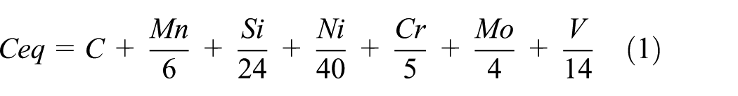
1. CE method
The two following formulas are chosen for the calculation of the CE


CS-300 carbon and sulfur analyzer.
JY38S spectrometer.
According to Japanese Industrial Standards G3106-1999, the CE can be calculated using formula (1) which is suitable to calculate the CE of low-carbon high-strength low-alloy steel that is hardened and tempered. Formula (2) is more precise for the calculation of the CE of steels with 3.4%–2.54% carbon.
2. Cold crack sensitivity index method
Considering the influence of the cooling speed, the degree of restraint and the diffusion of hydrogen on the tendency of hardenability, and cold cracking sensitivity, the following formula is obtained


where Pcm and Pc are called the cold crack sensitivity index numbers, [H] is the content of diffusive hydrogen in the welded metal, and T is the plate thickness.
3. Maximum hardness of the HAZ test
The tests in the Japanese Industrial Standards Z3101-1990 are conducted to determine the tendency of hardenability of the base metal. As shown in Table 1, JFE-EH400 and YMGR76 are used in the test. The preheating temperature is normal temperature, 80°C, and 120°C. The welding current and voltage are 220 A and 28 V, respectively.
Parameters of the maximum hardness of the heat-affected zone test.

As shown in Figure 5, approximately 12 h after welding, the specimen along the weld is made. The hardness of the positions is measured according to GB/T230.1-2009.
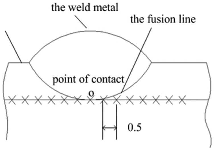
Measuring point of the heat-affected zone.
Y-groove cracking test
Y-groove cracking tests are conducted to determine the proper preheating temperature. In the tests, three combinations are considered: JFE-EH360+ZG30MnSi, JFE-EH400+ZG30MnSi, and HARDOX450+ZG30MnSi. YMGR76 and YMGR80 are used, and the preheating temperatures are 20°C, 80°C, and 120°C. A total of 18 pieces of specimens are made of EH360, EH400, and HARDOX450 in the test. The size and groove shape of each specimen are shown in Figure 6. The thickness is 40 mm. The length of YMGR76 and YMGR80 is 80 mm.

Specimen size and groove shape.
The restraint weld is obtained by double welding. After natural cooling for 24 h in air, the testing weld is made by single pass welding. The groove must be cleaned before welding. The preheating temperatures are 20°C, 80°C, and 120°C. The detailed welding parameters are listed in Table 2.
Welding parameters.

Approximately 48 h after welding, the crack is observed and measured following the steps below:
1. Observe and measure the surface crack (Figure 7), and then record the length of each crack, as shown in Figure 8.
2. Observe and measure the section crack

Welded joint of the Y-groove cracking test.

Parameters of the surface crack of the joint.
Cut the testing weld specimen into four or five slices of the same thickness, as shown in Figure 9; in this study, 86 pieces of slices were obtained. Observe and measure the section crack of each slice and record the depth, as shown in Figure 10.
3. Calculate the surface crack rate 1 (SCR1) and the section crack rate 2 (SCR2) using the following formulas


Slices of the testing weld specimen.

Crack parameters of the slice.
Mechanical property tests
Two tests are conducted. The aim of the first test is to study the influence of the preheating temperature on the mechanical properties of the welded joints when using the same base metal and welding wire. In the test, the combination is ZG30MnSi+JFE-EH360+YMGR76, and the preheating temperatures are 20°C, 80°C, and 120°C. The second test is performed to determine the more appropriate welding wire. The combination is ZG30MnSi+JFE-EH400. In the two tests, an SHT4106 electro-hydraulic servo universal tester and a JB-30B impact testing machine are used for the tensile tests, bending tests, and impact tests to obtain the mechanical properties of the welded joint (Figures 11 and 12). According to the mechanical properties, the proper welding wire is found:
1. First test
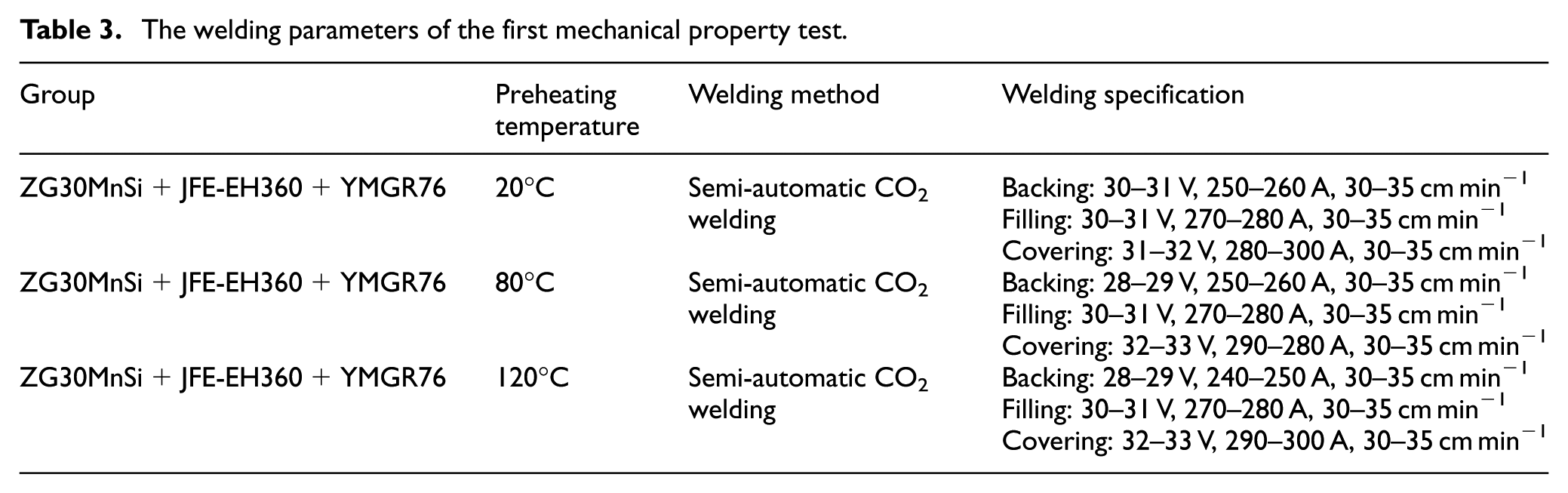
The seal baseboard is single cast with ZG30MnSi. It is cut into nine pieces of dimensions of 300 mm × 150 mm × 40 mm. JFE-EH360 is used to make nine pieces of middle plates, and the groove is machined using a planer to avoid the welding problem caused by cutting. A K-shape groove, as shown in Figure 13, is used between the edge ZG30MnSi and the middle plate JFE-EH360. The groove should be cleaned neatly, and the specimens are preheated to 20°C, 80°C, and 100°C separately before welding. The positive and negative alternating welding methods are applied. The welding parameters are listed in Table 3.
2. Second test
The aim is to test the strength of the weld joint of YMGR76 and YMGR80 and to determine which is more appropriate. The seal baseboard is single cast with ZG30MnSi. It is cut into six pieces, and the shape is 300 mm × 150 mm × 40 mm. Use JFE-EH400 to make six pieces of middle plates, and machine the groove using a planer to avoid the welding problem caused by cutting. A K-shape groove, as shown in Figure 13, is used between the edge ZG30MnSi and the middle plate JFE-EH400. Preheating temperature of 120°C is chosen. The positive and negative alternating welding methods are applied. The welding parameters are listed in Table 4.

SHT4106 electro-hydraulic servo universal tester.

JB-30B impact testing machine.

K-shape groove.
The welding parameters of the first mechanical property test.
Welding parameters of the second mechanical property test.

Results and discussion
Weldability and cold cracking of the welding wire and the base metal
1. Chemical composition and analysis of YMGR76 and YMGR80
Two types of high-strength welding wire, YMGR76 and YMGR80, are selected, and their chemical compositions are listed in Table 5. Compared with GHS-70, the ductile element Ni is increased by 21.7%, and fine-grained strengthening element is added in YMGR76. The ductile element Ni is increased by 88.4%, and solid solution strengthening element is added in YMGR80.
According to GB/T8110-2208 and B/T2652-2208, the properties of GHS-70, YMGR76, and YMGR80 are tested and listed in Table 6. The weld metal strength of YMGR76 and YMGR80 is found to be increased compared to GHS-70. The reduction in area is decreased.
2. Chemical composition and analysis of JFE-EH360, JFE-EH400, HARDOX450, and ZG30MnSi
The edge of central groove is cast with ZG30MnSi, and its chemical composition and heat treatment are listed in Table 7. The Ceq of the edge is approximately 0.56%. Hence, its weldability is poor. The contents of the elements S, P, and Si are high. Therefore, it is easy to form a liquid film and crack via the welding stress.
The middle plate steels and seal baseboard steels JFE-EH360, JFE-EH400, and HARDOX450 are finished goods from steel plants and are hardened and tempered before delivery. Their chemical compositions are listed in Table 8. The CE of JFE-EH360, FE-EH400, and HRDOX450 are 0.36%, 0.47%, and 0.52%, respectively. This indicates that they have a tendency of hardenability. The values of Pcm and Pc are calculated and listed in Table 9. According to Pcm and Pc, we know that they have a tendency of hardenability but not a high tendency.
3. Analysis of the maximum hardness of the HAZ test
The obtained hardness distribution curve is shown in Figure 14. When the preheating temperatures are normal temperature, 80°C, and 120°C, the maximum hardness values of HAZ are 376, 345, and 320 HV, respectively. According to the criterion proposed by International Institute of Welding that the critical hardness of steel welding cold crack is 350 HV and critical hardness of root crack is 330 HV, the base metals have a modest tendency of hardenability. The hardness of HAZ decreases after preheating. This indicates that preheating can reduce cold cracking sensitivity.
Chemical composition of the welding wire.

Properties of the welding wire.

Chemical composition and heat treatment of ZG30MnSi.

Chemical composition of JFE-EH360, JFE-EH400, and HARDOX450.

Pcm and Pc of JFE-EH360, JFE-EH400, and HARDOX450.


Hardness distribution curve of the test.
Analysis of the Y-groove cracking test
The calculated values of SCR1 and SCR2 are listed in Table 10. The Y-groove cracking test is conducted under very harsh constraint conditions. Hence, having the cold crack rate controlled under 20% will satisfy the engineering application requirements. According to Table 8, the following conclusions are obtained:
There is tendency of hardenability in the welding of high-strength-resistant steel and ZG30MnSi. The welding crack rate is too high under normal temperature. Therefore, preheating is required.
With combination 1, SCR1 is 0 and SCR2 is 2.3% and 0 when the preheating temperature is 80°C. With combination 2, SCR1 is 0 and SCR2 is 0 or 1.33% when the preheating temperature is 120°C. With combination 3, SCR1 is 0 and SCR2 is 1.00% or 12.5% when the preheating temperature is 120°C. This shows that using YMGR76 or YMGR80, the preheating temperature is decreased. The preheating temperature of 80°C for welding JFE-EH360 and ZG30MnSi meets the application requirements. For welding JFE-EH400 or HARDOX450 together with ZG30MnSi, 120°C meets the application requirements.
The crack resistance performance of YMGR76 is higher than that of YMGR80.
SCR1 and SCR2.

SCR1: surface crack rate 1; SCR2: surface crack rate 2.
The welding parameters are the same, and semi-automatic CO2 welding is used in each test. Combination 1 is EH360+ZG30MnSi, combination 2 is EH400+ZG30MnSi, and combination 3 is HARDOX450+ZG30MnSi. The 323 test is added because of an error.
Analysis of mechanical property tests
1. First test
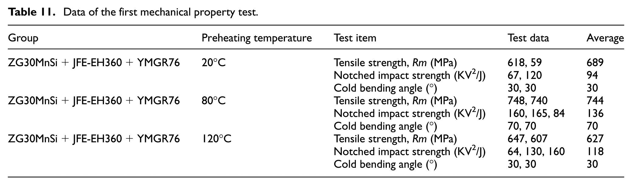
The tensile test is conducted to obtain the tensile strength, as shown in Figures 15 and 16. The bending test and the impact test are also conducted to obtain the notched impact strength and the cold bending property. These results are listed in Table 11. When the preheating temperature is 80°C, the tensile strength of the weld joint reaches the maximum value of 744 MPa, the impact strength reaches the maximum value of 136 KV2/J, and the cold bending angle reaches the maximum value of 70°. The mechanical properties of the weld joint have a rise–decline trend with the preheating temperature. When exceeding the suitable preheating temperature, the microstructure of the coarse grain HAZ grows with the increase in welding line energy; as a result, the grain size increases, thereby causing the decrease in the tensile strength, impact strength, and cold bending property. The test shows that preheating temperature is very important. Blindly increasing the preheating temperature to prevent cold cracking is not reasonable because the lack of cold cracking does not necessarily indicate good mechanical properties of the weld joint.
2. Second test
The tensile strength and cold bending property results are listed in Table 12. The tensile strengths of the weld joint of the different welding wires used in the last 4 years are listed in Table 13. As shown in Table 12, the mechanical property is better when using YMGR76 than YMGR80. The average value of the tensile strength and the notched impact strength reach 813 MPa and 112 KV2/J, respectively. Tables 12 and 13 show that the tensile strength of the welding joint of YMGR76 is the highest, and the average value is 813 MPa. This result shows that the states of the microstructure of the HAZ achieved the best condition with YMGR76 (Figures 17 and 18).

Tensile specimens.
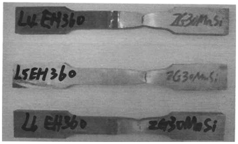
Broken tensile specimens.
Data of the first mechanical property test.
Data of the second mechanical property test.

Data of the tensile strength of different welding wire joints.


Tensile specimens.

Broken tensile specimens.
Figure 19 shows that excellent welded joints are achieved and welding defects, such as incomplete fusion, incomplete penetration, gas hole, inclusion, and segregation, do not exist around the HAZ of the joint. It is demonstrated that jointing of JFE-EH400 to ZG30MnSi can be successfully achieved using semi-automatic CO2 welding, with the YMGR76 or YMGR80 welding wire and the welding parameters shown in Table 4.

Macro metallographic photos of the weld joints in the second test: (a) jointing ZG30MnSi to JFE-EH400, with YMGR76 as the welding wire and (b) jointing ZG30MnSi to JFE-EH400, with YMGR80 as the welding wire.
Conclusion
The results of this investigation led to the following conclusions:
The central groove edge steel ZG30MnSi can be joined to the middle plate steel or seal baseboard steel JFE-EH360, JFE-EH400, and HARDOX450 using semi-automatic CO2 welding with either YMGR76 or YMGR80 welding wire, achieving welds with outstanding strength levels.
The cold crack rate of the dissimilar weld joints of the central groove decreases gradually with the preheating temperature. However, to achieve good mechanical properties, the preheating temperature must be controlled. An 80°C preheating temperature is recommended for EH360, and a 120°C preheating temperature is recommended for EH400 and HARDOX450.
The mechanical properties of the weld joints produced with the YMGR76 welding wire are better than those produced with the YMGR80 welding wire.
It is recommended that the central groove be welded using JFE-EH400 and ZG30MnSi, the YMGR76 welding wire, 120°C as the preheating temperature, and the welding parameters shown in Table 4. The strength of the weld joint is improved from 715 to 813 MPa. The toughness of the weld joint can be improved to 112 KV2/J.
Footnotes
Academic Editor: Xichun Luo
Declaration of conflicting interests
The author(s) declared no potential conflicts of interest with respect to the research, authorship, and/or publication of this article.
Funding
The author(s) disclosed receipt of the following financial support for the research, authorship, and/or publication of this article: This study is supported by the Fundamental Research Funds for the Central Universities (00/800015HJ), the National Natural Science Foundation of China (grant no. U1361127), and the National Key Research and Development Program of China (grant no. 2016YFC0600907).