
Abstract
This article researches the feasibility of use of a multimodal robotic system for upper-limb neurorehabilitation therapies in physical environments, interacting with real objects. This system consists of an end-effector upper-limb rehabilitation robot, a hand exoskeleton, a gaze tracking system, an object tracking system, and electromyographic measuring units. For this purpose, the system architecture is stated, explaining the detailed functions of each subsystem as well as the interaction among them. Finally, an experimental scenario is designed to test the system with healthy subjects in order to check whether the system is suitable for future experiments with patients.
Introduction
The use of robotic systems in neurorehabilitation therapies may be justified because of its potential impact on better treatment and motor learning. 1 For this reason, in the recent years, a wide variety of robotic devices for upper-limb neurorehabilitation have been developed by research groups around the world.2–11
In conjunction with these robotic devices, a wide range of robot-oriented rehabilitation interfaces and environments have been stated. Many of the current devices use virtual reality systems to set up the rehabilitation context;12–17 and just few examples use physical environments.18,19 It should be pointed out that all these examples, except Badesa et al.’s 14 work, use robotic exoskeletons.
Virtual reality systems are specially suitable for early stages of the disease, 20 due to the flexibility that it offers when designing tasks and feedback stimuli, and the safety that it provides due to the absence of interaction with physical objects that can lead to injuries. However, in order to obtain a realistic interaction, it is necessary to use haptic devices,21–24 which result in expensive and complex systems. In contrast, physical environments may suppose a good and inexpensive alternative to perform more complex, and functional, rehabilitation tasks in later stages of the disease, when patients have recovered some motor control of their upper limb.
The objective of this article is to check whether an end-effector rehabilitation robot 25 can be used to develop a fully functional multimodal rehabilitation system in physical environments. In contrast to Frisoli et al.’s 19 work, the use of an end-effector robot instead of an exoskeleton is expected to result in a considerable reduction in the setup time as well as in an increase in user’s comfort. Additionally, the brain–computer interface (BCI) is replaced by electromyography, which does not require previous training, reducing user’s mental fatigue 26 and saving additional time.
In this regard, the experimentation will focus on testing whether the mechanical system can be controlled with precision and safety enough to interact with some objects and perform a simple occupational therapy activity successfully, so that further researches in this path can be done.
Multimodal architecture
The starting point is an already designed upper-limb neurorehabilitation robot, which was conceived to deliver therapies in virtual reality environments, during the early stages after stroke.
In order to achieve the stated objectives, a multimodal architecture has been stated so that users can use a combination of their residual capabilities to perform the task. Among the possible remaining skills that patients may keep, eye movement and electromyographic (EMG) signals have been chosen for these tests.
Specifically, the designed system is composed of the following:
An object tracking system, which gives the position of the object that will be handled.
A gaze tracking device that will determine which object the patient is looking at.
EMG measuring units used as a trigger of several actions.
An end-effector rehabilitation robot that will assist the patient to perform reaching movements.
A hand exoskeleton for grasping the objects.
A computer that implements the high-level control (HLC) system, which will process and coordinate the signals of each device and will determine the control actions.
Communication and relationship between each element are stated in Figure 1.

System architecture and communications between components.
Upper-limb rehabilitation robot
The robotic device that is going to be used has 3 active degrees of freedom (DOFs), actuated by pneumatic drives, which are able to position the end-effector in any point inside the workspace of the robot; this workspace is such that it contains the positions that a mean human arm can reach, as presented in a previous publication. 25 Additionally, the end-effector has 3 passive rotational DOFs that allow the patients to freely orient their arm. These passive DOFs are sensed so that a reconstruction of the user’s arm can be performed. 27 Since the device acts on the forearm, the DOFs corresponding to the wrist are fixed by means of an orthosis attached to the end-effector of the robot.
This device was originally designed to deliver rehabilitation therapies in a virtual reality environment specifically designed for it. In this context, users try to reach several target positions with their wrist assisted by the robot. In this configuration, the end-effector is centered on the wrist and the control system monitors and positions this one.
In the studied application, due to structural issues, the part that is to be positioned (hand center) is different from the end-effector center (Figure 2), which now lies at a distance d on the forearm. Thus, it is necessary to transform the object grasping position to the end-effector position depending on the orientation of the forearm, so that the control system of the robot can compute control actions as shown in Figure 3. As an example, the result of a control test, for the Z-coordinate of the robot (height with respect to the ground), is displayed in Figure 4. In this test, a constant hand target is stated and the system computes the reference needed to place its end-effector in the proper position; it can be seen that the variation in the forearm orientation involves a coherent change in the reference of the end-effector.
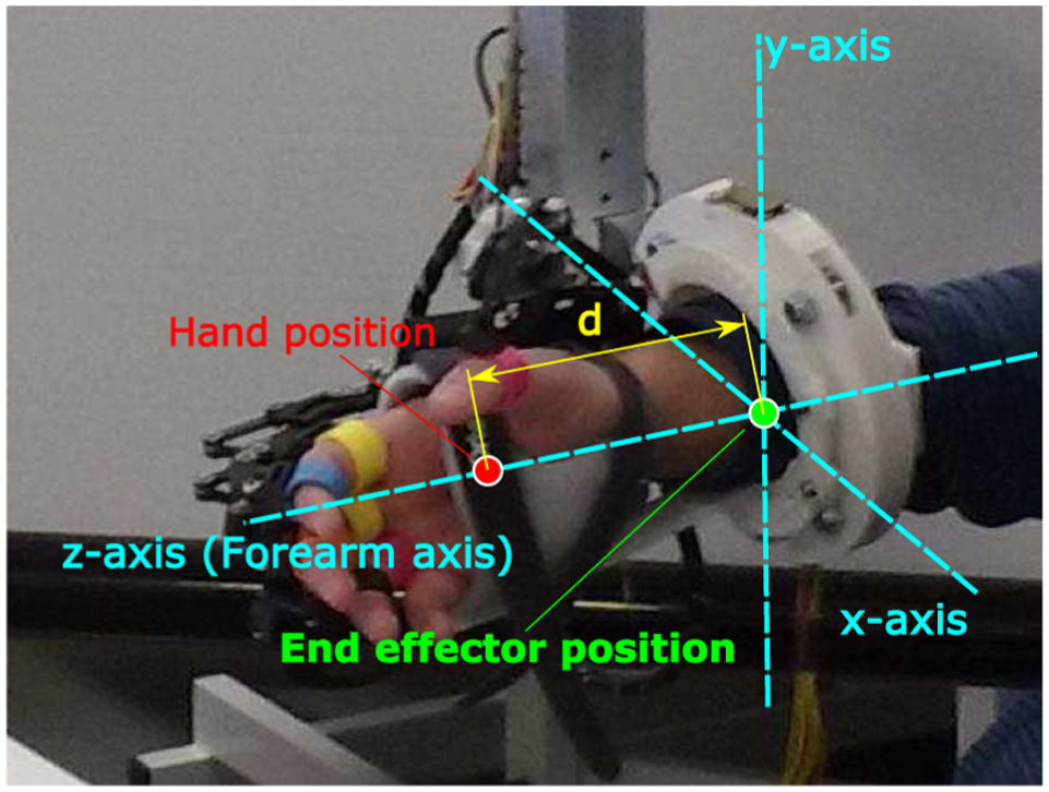
Difference between hand position and end-effector position with respect to the reference frame of the end-effector.

Block scheme used to control the position of the end-effector of the device, with an additional loop for dynamically adjusting the end-effector reference sent to the PID controller.

Example of robot control tasks, where the hand reference is a constant height with respect to the ground (Z-axis of the world reference frame). Top figure shows the evolution of the reference and actual signals, while the plot in the bottom displays the measured coordinate that controls the end-effector reference.
This upper-limb robot implements an experimental controller based on the potential and force fields. 28 This method consists of stating a force field, along the whole workspace, such that the target point has the minimum potential; therefore, the system will exert an action on the end-effector in order to reach this point. The gradient of the force field becomes sharper over the time, so the system helps slow users (which are supposed to have difficulty when performing the task) while offers low or null aid to the faster ones. A more detailed description of the algorithm implementation can be found in previous publications.28,29
Hand exoskeleton
In order to interact with physical objects, it is necessary to use a device that can assist hand movements. The most suitable kind of device to reach this purpose is a hand exoskeleton.
The exoskeleton that will be used in this case is based on a pneumatic rehabilitation robot already designed, 30 which was designed specifically for rehabilitation applications. The current design is an electrical-driven robot for both rehabilitation and assistance applications which uses five linear actuators to move each finger independently (Figure 5). The stroke of the actuators is sensed so that the finger pose can be estimated by means of its direct kinematics.
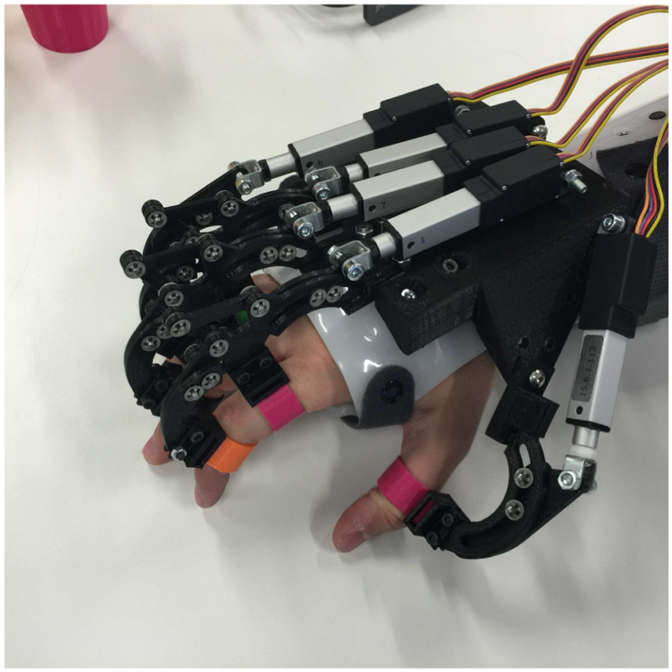
Detailed view of the hand exoskeleton.
Gaze tracking system
The Gaze tracking system is based on the information provided by the Tobii Pro Glasses 2. This wearable eye tracker device is capable to send wirelessly a live streaming of video and data simultaneously by WiFi communication. The live video provided by the scene camera (full HD, 1920 × 1080, 25 fps) is in H.264 compression format. This live video visualization only serves to have a feedback about what the user is looking at. The gaze position is included in the data set provided by the stream of data. The coordinates of the gaze position make reference to the visual captured by the scene camera, because of this they are normalized by the video frame size.
A color-matching recognition algorithm (Figure 6), based on hue, saturation, and value (HSV) color coding, is used for discerning which is the object that the patient is looking at. In order to reduce the processing time, just the image of the surroundings of the gaze position is processed. To do that, a threshold that depends on the object size, the distance of the object, and the error committed during the calibration process is defined. This parameter is used to delimit a piece of image centered in the gaze point, as the highlighted one in Figure 7. Inside this snippet, the percentage of each stated color is computed, so when a threshold is overcome during a certain amount of time, the detection of the corresponding object is triggered (Figure 13, bottom).

Object identification algorithm.
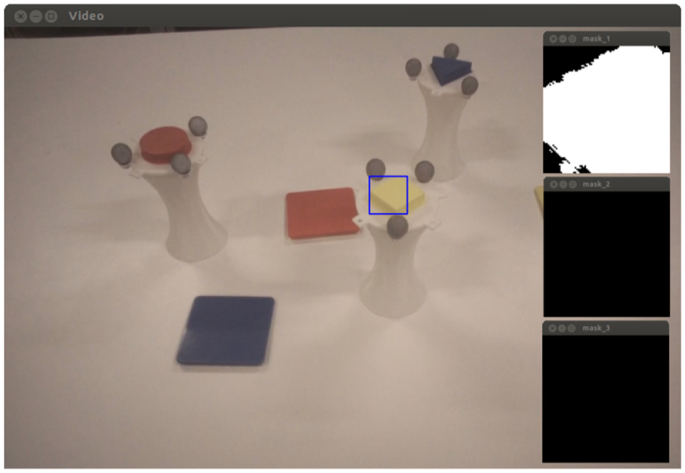
Left: image from Tobii Glasses with the surroundings of the gaze position highlighted with a blue square. Right: color masks (yellow, magenta, and cyan) applied to the snippet.
Object tracking system
Since physical environments are prone to the changes and imprecision, it is necessary to have a system capable to detect those changes, in this case the variability in the position of the target objects. A visual tracking system has been chosen for this purpose, concretely the OptiTrack Trio camera system. This device is composed of three pre-calibrated infrared cameras that are able to track the position of several highly reflective markers (gray spheres in Figure 7). Each object has a characteristic distribution of markers so that the tracking system can clearly discern each of them and track their position in real time.
The position given by the OptiTrack Trio is referred to its own reference system, which differs from the robot’s one. In order to compute the transformation matrix between both the devices, a calibration process needs to be performed to relate both the coordinate systems if cameras or robot have been moved. This calibration proceeding consists of placing objects in four arbitrary positions and reaching them with the end-effector. Then, for each position i, coordinates given by the robot


Calibration error distribution for each coordinate. Red lines denote the median of the error; blue boxes show the mean and standard deviation; black dotted lines cover the range of the error.
Both object tracking system and gaze tracking system work together as shown in Figure 9 to find out which object the user is looking at and send the correct grasping position to the HLC system.

Software architecture and communications between the elements of the tracking system.
Electromyography units
For triggering the opening and closing actions of the hand exoskeleton, a Shimmer3 EMG unit has been selected, which provides two differential channels for EMG measurement that will be used for detecting the flexion and extension of forearm muscles, as shown in Figure 10.

User with EMG unit and electrodes. Left: electrodes over extensor digitorum muscle. Right: electrodes over flexor digitorum superficialis muscle.
The chosen triggering method is based on applying a threshold on the envelope of the EMG signals, which implies a simple and fast treatment process. For this purpose, a high-pass filter with 5 Hz cutoff frequency is applied to the raw data, so that if any DC offset or drift is reduced, the result is rectified by applying the absolute value; finally, the obtained signal is treated by a low-pass filter of 5 Hz to get the envelope (Figure 13). The activation threshold varies significantly among users and conditions, so this value must be calibrated before performing the activity.
High-level controller
All the elements mentioned above are coordinated by a high-level controller which implements the state machine shown in Figure 11. This subsystem controls the transition between states and acts as an intermediary in the communication flow, adapting it to the format that each device might need. This architecture will allow to change technologies of each component without affecting the performance of the rest of the elements, for example, EMG triggering might be changed to electroencephalogram (EEG) or electrooculogram (EOG) interface without the need for the changes in robot controller or tracking systems. Moreover, according to the residual capabilities of the user, some states might be automatized, in order to maximize the kind of disabilities that can be treated with this system.

State machine diagram of the implemented HLC.
System validation
In order to check the feasibility, stability, and safety of the system, an experimentation has been performed with healthy subjects.
Experimental setup
The experimental test consists of performing a simulated rehabilitation scenario, in which users must perform a simple reaching task, where they have to match colors, as follows:
The user has to look at the object that the therapist tells him.
The tracking system will recognize which object the user has chosen and will send its position to the control system.
The robot will compute and perform the suitable actions to assist the user to reach the target, and the subject should not perform the movement by himself, even opposing to the actions of the robot.
Once the user is close to the grasping position, the hand must be closed using the EMG trigger.
After that, the user must look at the target that he or she considers is the correct place to release the object.
Again, the tracking system jointly with the robot will assist in the fulfillment of the action.
At the release position, the user must trigger the opening of the hand again by EMG signal.
The robot takes the user to the rest position and waits for further instruction from the therapist.
The grasping objects used in this experiment are specially designed for it and consist of white cup-like recipients with a design easy to grasp, crowned by a cap with a colored (magenta, yellow, blue) geometric shape and a concrete distribution of reflective markers. The releasing targets are square cup holders; the color of each one corresponds to the color of one grasping cup. Both kinds of item are shown in Figure 7.
The subject will perform the activity in sitting position, with the objects lying on a table in front of him, just as shown in Figure 12.

Experimental setup with each involved device.
Once the scenario is established, tracking system must be calibrated just once and is valid while cameras and robot frame remain in the same position. Hence, setting up the system on the user implies few simple tasks that require about 5 min, for healthy subjects, as follows:
Wearing the Tobii Glasses (30 s)
Attaching EMG unit (30 s)
Setting up the end-effector on user’s arm (2 min)
Fixing hand exoskeleton to user’s fingers (2 min)
When setting up users with impaired mobility, these times are expected to be higher. However, until further research is performed, it is assumed that the arrangement of the system is simple enough to be suitable in a clinical scenario.
Results
The system validation involved six users, between 24 and 32 years old from the staff of Biomedical Neuroengineering Group of Miguel Hernández University; all of them with no major cognitive or physical deficits. Each subject performed three grasping–releasing cycles.
Figure 13 shows the state and evolution of the different subsystems along the performance of one cycle of grasping and releasing for a healthy subject. Some results can be drawn as follows:
The robot position graph shows that this device is precise enough to reach the target points in a short amount of time with a stable response. In every iteration, the robot was able to approach the user’s hand within the tolerance area defined in section “Object tracking system,” and that position was suitable for successfully grasping the object.
From the EMG plots, despite that the detection is only computed in its respective states to avoid false-positive readings in other than hand opening/closing phase, it can be seen that the influence of the arm movements is negligible in the EMG signal of the chosen muscles.
During the tests, a total of 36 EMG detections were performed with a success rate of 83%, with 14% false-positives and 3% false-negatives.
The figure related to the color detection shows that the selected colors are suitable for the tests since there is no overlap between them and other colors present in the environment. Color detection got a success rate of 100% for healthy users, so further tests with patients must be performed to evaluate the actual performance of the system.

Experimental results for one cycle of grasping and releasing.
Conclusion
According to the obtained results, the system has proven to be feasible and safe enough, since control instabilities have not been found. Wrong detections in EMG are the main cause of failure; however, in the 97% of the trials it still resulted in successful grasping and releasing.
The next step consists of conducting an experimentation with a statistically representative group of healthy subjects, such a database can be compiled to compare with further therapies with disabled people.
The developed technology, which allows the user to choose targets and interact with them using a robotic device, also offers the possibility of using this system for assistance purposes in activities of daily living (for instance, eating, drinking, entertainment, etc.), which may result in another potential development line.
Footnotes
Academic Editor: Ruey-Jen Yang
Declaration of conflicting interests
The author(s) declared no potential conflicts of interest with respect to the research, authorship, and/or publication of this article.
Funding
The author(s) disclosed receipt of the following financial support for the research, authorship, and/or publication of this article: This work has been supported by the European Commission (ICT-22-2014: Multimodal and Natural computer interaction) through the project AIDE: Adaptive Multimodal Interfaces to Assist Disabled People in Daily Activities (grant agreement no. 645322), The Ministry of Economy and Competitiveness through the project DPI2015-70415-C2-2-R, and The Biomedical Research Networking Center (CIBER). CIBER gives support to our research group inside the line of Bioengineering and Medical Imaging. Specifically, our research group, Neuroprosthesis and Neuroengineering Research Group, has been financially supported for the development of new research lines, such as multimodal rehabilitation devices, among others.