
Abstract
According to structural characteristics of dual-effect strong side-cut window bit (hereinafter referred to as window bit) and the theory of metal cutting and the rule of teeth arrangement of window bit, a cutting mechanical model of window bit cutting teeth is established, window bit geometric equations deduced and the solution of the cutter cutting mechanical model completed; finally, the casing window experiment is conducted with the dual-effect strong side-cut window bit developed to verify the accuracy of the cutting mechanical calculation model and the simulation results. The results show that the variation tendency of the main cutting force of the bit and the experimental data are similar in the windowing process, the simulation results can accurately reflect the change rule of the main cutting force and the requirements of engineering applications are basically met. The research results of this article provide theoretical basis for the analysis and calculation of the cutting force of the window bit and can serve as a reference for the design of deep/ultra-deep well casing window bits and cutting mechanics research.
Introduction
Casing window sidetracking has become a key technology in the fields of remaining oil and gas development and downhole accident handling. The success and efficiency of window sidetracking mainly depend on the structure of the window drill bit and reasonable construction parameters.1,2 Currently, the main casing window drill bit is taper mill. Cutting teeth are mainly cemented carbide particles welded on the taper mill matrix (Figure 1) in the form of “spiked bats” made of cemented carbide particles of the same particle size. Cutting edges are randomly distributed and of different shapes. 3 The main cutting method is milling. It can be seen from the structural features and mode of operation of the taper mill that it is hard to build a cutting mechanical model for the taper mill, which has made it very difficult to design the structure of the taper mill and determine the window cutting parameters. Moreover, current taper mill structure should meet cutting requirements of not only casing but also cement sheaths and stratum rocks and in effect the taper mill also needs to be equipped with a whipstock, which often causes the cemented carbide particles of the taper mill to be severely worn when cutting metal. Consequently, the cutting efficiency of cement sheaths and rocks is extremely low and it often costs several taper mills for window sidetracking operation on high-strength thick-walled casing, 4 thus resulting in long operation time, low window sidetracking efficiency, and even window sidetracking failures due to broken taper mill.5–7 It is thus clear that existing taper mills can no longer meet the window sidetracking requirements of casing in deep/ultra-deep well sections with hard formation. 8 The development of a new window bit that can cut both high-strength thick-walled casing and cement sheaths/rocks is quite necessary to reduce the risks of casing window sidetracking in deep/ultra-deep well sections with hard formation and improve operation efficiency.
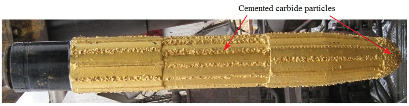
Taper mill.
In order to meet the requirements of deep/ultra-deep well and hard formation window sidetracking operations, a new type of window bit was designed. 9 It adopts a set of composite teeth to, respectively, achieve the functions of side-cut casing and cut the cement mantle/rocks. Because the difficulty of deep/ultra-deep well hard formation window sidetracking operations lies mainly in cutting high-strength thick casing pipes, cutting teeth of side-cut casing of the drill bit are mainly cylindrical cemented carbide teeth. Thus, the action way between the teeth and the casing pipe is changed from milling to cutting but the main cutting method for cement mantle/rock is still milling. Given the uniformity of the size and form of cylindrical cemented carbide teeth and their regular distribution on the bit body, the cutting force and strength of the drill bit could be analyzed and calculated theoretically, and it can also lay the foundation for reasonable determination of drilling parameters. 10
Ayatollahi et al. 11 utilized the experimental technique of photoelasticity for calculating bi-material notch stress intensities as well as the coefficients of higher-order terms. Employing the equations of multi-parameter stress field allows data collection from a larger zone from the notch tip and makes the data collection from experiments more convenient. Ayatollahi et al. 12 evaluated the influence of the first non-singular stress term on the stress field near the bi-material notches and carried out an extensive study on the higher-order eigenvalues and their correlation with the notch angle and the material combination of the bi-material joints. Mirsayar 13 modified the maximum tangential strain criterion to predict fracture initiation in cracked specimens under mixed mode loading conditions. Afterward, he introduced a modified maximum tangential stress criterion considering the effect of T-stress and critical distance theory and compared to three traditional fracture criteria. 14 The criterion takes into account the effect of T-stress as well as the stress intensity factors to predict the mixed mode fracture toughness of interface cracked specimens.15,16 Xu et al. 17 established a mechanical analysis model, which was used to analyze the force on mill, and developed a software for the mechanics analysis of the mill. In addition, various experiments were conducted to verify the mechanical analysis model and the simulation results.
Structural characteristics of dual-effect strong side-cut window bit
Taking into account the window bit cutting casing and the demand of drilling formation condition, a parametric design method is adopted to complete the design of dual-circular arc contour of window bit (Figure 2).

Window bit matrix contour line.
Design features of the drill bit are as follows:
The structure of the drill bit matrix surface is a combination of inner cone-dual-circular arc and a cylindrical surface and busbars of them form the drill bit matrix contour line.18,19 A complete window bit model is shown in Figure 3.
Due to the poor formation drilling ability after deep/ultra-deep well casing window sidetracking, the Balas teeth for rock cutting were set on the inner cone-dual-circular arc surface and the cylindrical surface of the drill bit matrix, with a toothy height below the cemented carbide teeth of 0.5–1 mm.
The distribution baseline of the cemented carbide teeth is a three-dimensional (3D) equidistant helix, which starts from the center of window bit matrix. The pitch varies according to the shape, size, and the window bit footage of the cutting teeth.20,21
Cemented carbide teeth are arranged on the points of intersection of the equidistant helix and the window bit contour lines in the axial-planes of bit matrix (Figure 4). Three main cemented carbide toothed belts (1, 2, and 3), starting from the first row helix (Figure 4), are distributed on the inner cone-dual-circular arc surface and ends on the cylindrical surface. The remaining three cemented carbide toothed belts (4, 5, and 6) successively start from the second and the third row spiral and end on the cylinder surface.
Spatial distribution of all cemented carbide teeth of the window bit designed according to the teeth arrangement principles mentioned above is shown in Figure 3.

Solid modeling of window bit.
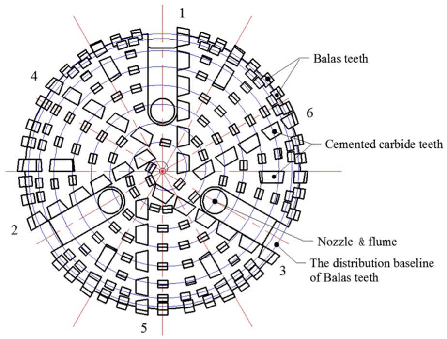
Teeth arrangement of the window bit head face.
Compared with the taper mill as shown in Figure 1, the window bit shown in Figure 3 has a flat profile, smaller width and length, and a shorter cutting surface. According to the research results of Nawaz, 22 drill bits with such profile have stronger side-cutting ability and the window bit can realize the function of side-cut.
Working mechanical model of the window bit
The interaction between the window bit and the casing is similar to the metal cutting process. Every cylinder cemented carbide tooth on the bit can be seen as a cutter, and the window bit is an aggregate of multiple cutters,23,24 with the collection of cutting forces of the cylindrical cemented carbide teeth serving as cutting force of the window bit. Analysis of the interaction between the window bit and the casing shows that not all cylindrical cemented carbide teeth conduct same cutting operations simultaneously. Teeth actually involve in cutting are mainly those on the tooth bit head, followed by those on the arc-cylindrical transition tooth surface, and the remaining tooth surfaces only play the role of window repair. Cutting force of the bit head tooth surface is about 80% of total cutting force of the window bit.25,26 Therefore, this article focuses on the cutting mechanical analysis by taking cylindrical cemented carbide teeth on the window bit head as an example.
According to geometric model features of the interaction between the cemented carbide teeth and the casing, the model for calculation of window cutting force is established with the single blade orthogonal model (Figure 5) 24 for metal cutting.

Single blade orthogonal model.
As shown in Figure 5, assume that there is a shear force Fs and normal force Fns acting on the plane AB, the resultant force Frs acting on the shear plane and the joint force Frf of normal force Fnf, and friction Ff acting on the contact area between the cutting face and cutting tool front face. According to the force equilibrium condition, Frs and Frf are equal and opposite in direction and act on the same straight line.
Since

where
Project resultant force on the shear plane on the normal direction of the cutting speed and the cutting plane and we can get the formula of the main cutting force Fd and formula of the normal force Fn of cutting plane
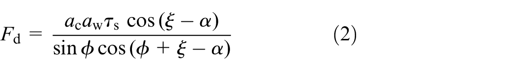
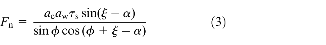
where ac and aw determined according to the cutting edge and cutting depth; for the cutting of conventional metal, they can be determined according to cutter parameters and cutting feed. They are direct and can be easily obtained. As for the casing cutting process of the cylindrical cemented carbide teeth (hereinafter referred to as cutting teeth) on the window bit, it is necessary to determine them according to the cutting edge shape of the cutting teeth, the footage of the window bit, and the spatial position of the teeth on the bit. 27
Geometric equations of window bit
Geometric coordinate system of window bit
Prior to discussion on the formation and calculation of cutting cross section of the cutting teeth, we need to make the following assumptions: the window bit runs without eccentricity or no revolution and the impact of the fluid medium on the window bit cutting force is not taken into account. The window bit coordinate system established is shown in Figure 6.
Establish the window bit cylindrical-coordinate system ORHΘ: OH-axis passes through the bit axis and points to the bit drilling direction. The space coordinates of the center of a cutting tooth on the drill bit can be expressed as (Rc, Hc, Θc).
Establish the position coordinate system o1x1y1z1 of the cutting teeth: o1z1//OH and its direction is the same as the OH-axis. The direction of o1y1 and that of the circumferential line speed of the drill bit (at point o1) are the same.
Rotate o1x1y1z1 clockwise around the o1y1-axis for an angle of γ (the complementary angle of the included angle between the baseline of teeth and the bit axis), to obtain the coordinate system o1x2y2z2; o1x2 and baseline of cutting teeth are collinear and o1x2 points to the outside of the bit matrix.
Rotate o1x2y2z2 clockwise around the o1z2-axis for an angle of β, to obtain the coordinate system o1x3y3z3. It is obvious that the geometrical characteristics of the cutting teeth can be expressed in mathematical form in this coordinate system.

Geometric coordinate system of the window bit and teeth.
Geometric equations of window bit
As shown in Figure 6, in the coordinate system o1x3y3z3, the parameter equation of the outline of cutting teeth is
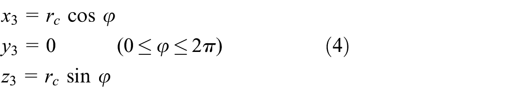
where rc is the radius of cutting teeth.
Rotate coordinate system o1x1y1z1 clockwise around the o1y1-axis for γ, to obtain the coordinate system o1x2y2z2. Then, rotate coordinate system o1x2y2z2 clockwise around the o1z2-axis for an angle of β, to obtain the coordinate system o1x3y3z3, see formula (5)

Finally, transform the coordinate system o1x1y1z1 into the coordinate system ORHΘ of the drill bit, as follows

Combining equations (4)–(6), the equation of the contour line of cutting teeth edge can be obtained. The plane passing through the window bit axis is axis plane Ni. The outlines left by the cutting teeth passing in turn through axial-plane Ni form the cutting cross section of the teeth. It can be seen from the rule of tooth arrangement of the window bit tooth surface that the cutting cross section of a tooth is related to the space location of adjacent teeth to its front and back on the bit, and contours left by them on the axial-plane as well as the footage of the window bit. The cutting cross-section contour line equation of cutting teeth determined by these factors will be discussed in detail in the following.
As shown in Figure 7, cutting cross-section diagram of cutting teeth is the contour lines left by the cutting teeth on the axial-plane when the window bit makes one revolution without the footage. Take tooth n as the analysis object. The adjacent teeth before it is n − 1 and the adjacent teeth after it is n + 1; the coordinates of their centers in the coordinate system of the drill bit are (

Coverage diagram of the cutting cross section of cutting teeth.
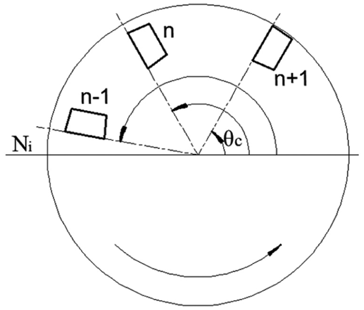
Circumferential position of teeth.
When drilling footage of window bit is given, assuming that the heights of teeth n passing through the axial-plane Ni in the former revolution and the current revolution are
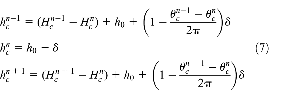
where δ is the drill footage of each revolution.
As shown in Figure 9, the contour lines of cutting cross section of cutting tooth n are made up of the contour line

Schematic diagram of the formation of cutting cross section.
The equations of contour line Ln produced by tooth n passing through the axial-plane Ni of the drill bit in the current revolution are as follows


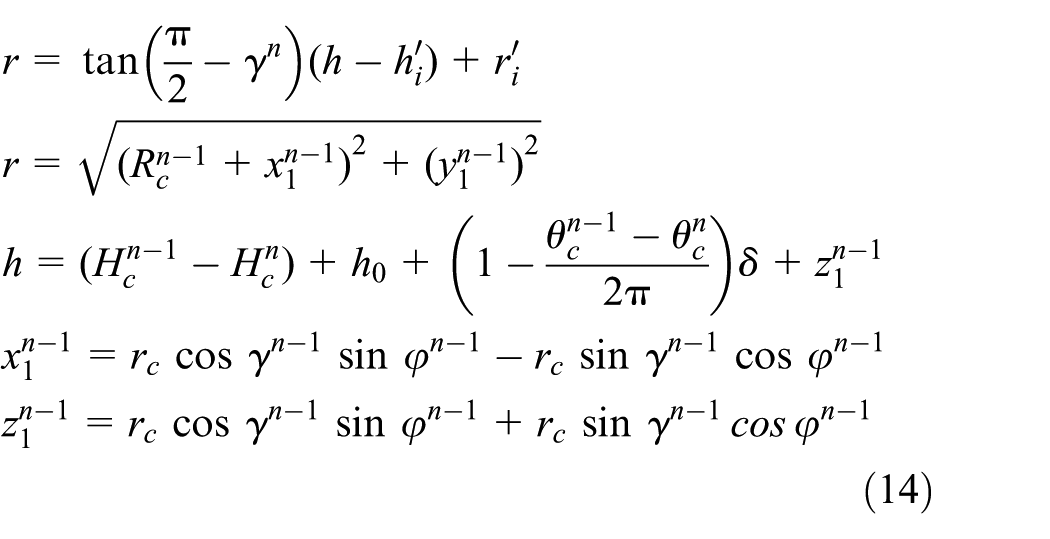
The equations of contour line

The equations of contour line Ln − 1 produced by tooth n − 1 passing through the axial-plane Ni of the drill bit in the current revolution are as follows


The equations of contour line Ln + 1 produced by tooth n + 1 passing through the axial-plane Ni of the drill bit in the current revolution are similar to those of contour line Ln − 1 and we only have to change the superscript n − 1 in the equations of Ln − 1 to n + 1, so the equations of Ln + 1 are omitted here.
As can be seen from the above analysis, cutting cross section of cutting teeth is of irregular shape composed of different arcs and cannot directly calculated with the formula of the single blade orthogonal cutting model, so the infinitesimal method is required to calculate the cutting force of teeth.
1. Calculation methods for coordinates of vertices on cutting cross section of tooth n
Vertices on cutting cross section of tooth n are shown in Figure 9. Point 1 (r1, h1) is the intersection point of contour line Ln and contour line Ln − 1. Point 2 (r2, h2) is the intersection point of contour line Ln and contour line Ln + 1. Point 3 (r3, h3) is the intersection point of contour line
2. Micro-unit division of cutting cross section
In the baseline coordinate system of tooth n, with inscribed angle


Micro-unit division of cutting cross section.
Passing through the equal-part point (ri, hi), make a straight line parallel to direction of datum line of the current tooth and the straight line intersects curve Ln − 1 (
3. Calculation of the micro-unit of cutting cross section
The micro-unit of cutting cross section is shown in Figure 10. Points a and b are two adjacent equal-part points on the curve Ln. Points c and d are, respectively, intersection points of between parallel lines passing through points a and b and the curve Ln − 1 (

The divided micro-unit complies with the single blade metal orthogonal cutting calculation model, and the main cutting force and the normal force of micro-unit are, respectively, expressed as formulas (16) and (17)


Cutting force of the entire tooth is the summation of all the cutting forces of the micro-unit, as shown by formulas (18) and (19)

Simulation and experimental verification
According to the geometric parameters of the window bit and the cutting mechanical analysis model established, casing cutting process of the window bit is simulated and calculated by compiling computer program with MATLAB software and main cutting forces on cutting teeth in the sidetracking process are calculated. In order to verify the accuracy of the cutting mechanics model and the simulation results, the window bit with an outer diameter of 149 mm is employed to carry out casing sidetracking experiment on the casing with a diameter of 177.8 mm (Figure 11), steel grade is TP110TS and wall thickness is 12.65 mm. The basic parameters of the experiment: the lead angle of the whipstock is 6°, WOB is 2t, and speed is 70 r/min.

Sidetracking experiment of window bit: (a) before the experiment, (b) after the experiment, (c) casing window, and (d) iron cuttings.
Results obtained from the experiment and main cutting force of dual-effect strong side-cut window bit obtained through simulation are shown in Figure 12. In the initial stage of the drill casing cut, the main cutting force obtained through simulation and calculation is slightly larger than the experimental data, slightly smaller in the intermediate stage, and slightly larger in the later stage. But the variation tendency of the calculated main cutting force and the experimental data of window bit are similar. It indicates that the cutting mechanical model of window bit established in this article is correct, and the calculated results can accurately reflect the change rule of the main cutting force and the requirements of engineering applications are basically met. 17

Comparison of experimental and calculation data.
Conclusion
In this article, teeth cutting mechanics analysis is conducted on the dual-effect strong side-cut window bit designed and developed based on special problems with casing window sidetracking in deep/ultra-deep wells. Based on the metal cutting theory, the cutting mechanical model for the cutting teeth of window bit is built, the geometric equations of the window bit established and derived, and the solution of the cutting mechanical model completed. Finally, the casing window experiment is conducted with the dual-effect strong side-cut window bit developed to verify the accuracy of the cutting mechanical calculation model and the simulation results. The results show that the variation tendency of the main cutting force of the bit and the experimental data are similar in the windowing process; the simulation results can accurately reflect the change rule of the main cutting force and the requirements of engineering applications are basically met. The research results of this article provide theoretical basis for the analysis and calculation of the cutting force of the window bit and can serve as a reference for the design of deep/ultra-deep well casing window bits and cutting mechanics research.
Footnotes
Acknowledgements
Author Derong Zhang is now affiliated with College of Mechatronic Engineering, Southwest Petroleum University, Chengdu, China.
Academic Editor: Filippo Berto
Declaration of conflicting interests
The author(s) declared no potential conflicts of interest with respect to the research, authorship, and/or publication of this article.
Funding
The author(s) disclosed receipt of the following financial support for the research, authorship, and/or publication of this article: This research work was supported by the National Major Projects of China (No. 2011ZX05049-002-002) and the Southwest Petroleum University Graduate Innovation Fund (No. CX2014BY06).