
Abstract
A spherical single-roller bit based on polycrystalline diamond compact (PDC) cutters is designed for the purposes of improving the adaptability of single-roller bit to the stratum with high hardness and abrasiveness. According to the characteristics of cutter shape, the distribution of cutter, as well as the mode of contact between cutter and rock, the methods of space analysis and coordination projection are used to establish the geometrical equation for the single-roller bit with PDC cutters and the velocity equation for the PDC cutters, to describe the change rules between the velocity and other parameters. It is concluded that the velocity is subject to high influence by the shaft inclination angle and the positions of PDC cutters, but is subject to low influence by the radius, lateral rotation angle, and front inclination angle of PDC cutters; the velocity of cutters can be affected by the rock stratum to some extent and is higher in soft rock than in hard rock; the velocity of PDC cutters varies at different positions on the roller, and the absolute velocity of the most cutters on the roller will become stable along with the increase in the shaft inclination angle, while great increase will be found in the velocity of the cutters near the top of roller, where the distribution of cutters is to be strengthened; the shaft inclination angle is to be designed larger than 53° and is suggested to range from 53° to 70°. This study lays the foundation for the computer simulation research related to the single-roller PDC bits and the structural design optimization of cutter surfaces.
Introduction
The single-roller bit is a new design between the PDC bit and three-roller bit to inherit their merits and overcome their insufficiencies, 1 with particular superiorities shown in deep drill holes and slim drill holes.2–4 At present, the spherical single-roller bit 5 (Figure 1(a)) in service are all made of inserted cemented carbide cutters, for example, cone, wedge, spoon, and flat cutters, which have high mechanical drilling rate and long service life in soft stratum, but is unfavorable in these parameters in the stratum with high hardness and abrasiveness due to the low abrasive resistance of cutters (Figure 1(a)). Wang6,7 and others make approaches by changing the shape of roller to change the motion mode of cutters, reduce the cutting distance of cutters, reduce the wear of cutters, and prolong the service life of bit. However, the anomalous single-roller bit is not a full pack bit, and the roller cutters have serious wear, short service life, and relatively low rock breaking efficiency, since the roller can only pack a part of the drill hole, and only a limited number of cutters are distributed on the small roller surface to enable a limited number of cutters to contact against the stratum. The spherical single-roller bit is a full pack bit which can cover the full size of the drill hole to improve the stability of drilling tool without any eccentric loads. 6

Single-roller bit: (a) conventional single-roller bit and (b) single-roller PDC bit.
Ma 8 found the modern geometry and kinematics of roller bit. Deng et al. 9 and Yu and colleagues10,11 study the geometry, kinematics, and dynamics of spherical single-roller bit and explored the structural design for the cutter surface of single-roller bit. Zhao et al. 12 make analysis on the influences of cutting structure and cutter exposure, as well as longitude and latitude of cutter distributing surface of roller, on the down-hole coverage and cutting homogeneity of single-roller bit. Deng et al. 13 study on the influences of lateral rotation angle on the cutting area. Yu et al. 5 study on the influences of different geometrical parameters, motion parameters, and cutter surface structure on rock breaking and find by simulation that the down-hole track is very similar to the mode of actual rock breaking. Li et al. 14 suggest to use axis-symmetric cutters within the permanent area on the working surface of roller and to use oval cutters within the alternate contact area.
All existing studies in connection with the geometry of roller bit are based on the assumption that a cutter can be simplified as a point on the surface of roller. As shown in Figure 1(b), changes are made to the characteristics of cutter shape and style of cutter distribution on the single-roller bit based on PDC cutters, so that a characteristic point on the PDC cutter blade cannot be simplified as a point on the spherical surface of roller, and the equations for geometry and kinematics shall be reestablished for the cutters of single-roller PDC bit.
Establish coordinate system
Motion of single-roller bit includes rotation of bit and roller around the central line of bit, motion of bit and roller along the central line of bit, and rotation of roller around the roller shaft. Any studies on the basic motions of cutters on roller shall be based on deep understanding of the features of bit in the coordinate system, basic plane, and structure.
Static cylindrical coordinate system
Use the central axis of a single-roller bit as the coordinate axis OZ to establish a static/fixed cylindrical coordinate system (static coordinate system), 9 set the polar axis on a horizontal reference plane and in a certain direction. Thereafter, a point Q within the space can be represented by Q (ρ, θ, Z), wherein ρ = radius vector, θ = polar angle, and Z = vertical height, as shown in Figure 2.

Cylindrical coordinate system for bit.
Dynamic cylindrical coordinate system
Set up a dynamic cylindrical coordinate system for a single roller, 9 with the origin O′ set at the bottom center point of roller, the vertical axis O′H′ coinciding with the axis of roller, and polar axes O′X′ and O′H′ perpendicular to each other. The plane defined by H′O′X′ is called as a polar axis plane of roller. A point on the roller can be indicated by the radius vector r, polar angle α, and vertical height h, as shown in Figure 2.
Figure 3 shows the projection relationships of a complex cylindrical coordinate system, including (a) view from direction A for the back cone plane of roller, (b) front view of single roller, and (c) top view in addition to (b). Figure 3 indicates the parameters for bit structure as (L, R, β), parameters for bit and roller positions as (θ0, ZO′, α0), parameters for PDC cutter’s position on roller as (hC, rC, γ, δ, η), and parameters of point Q’s position on PDC cutter blade profile as (rQ, φ).
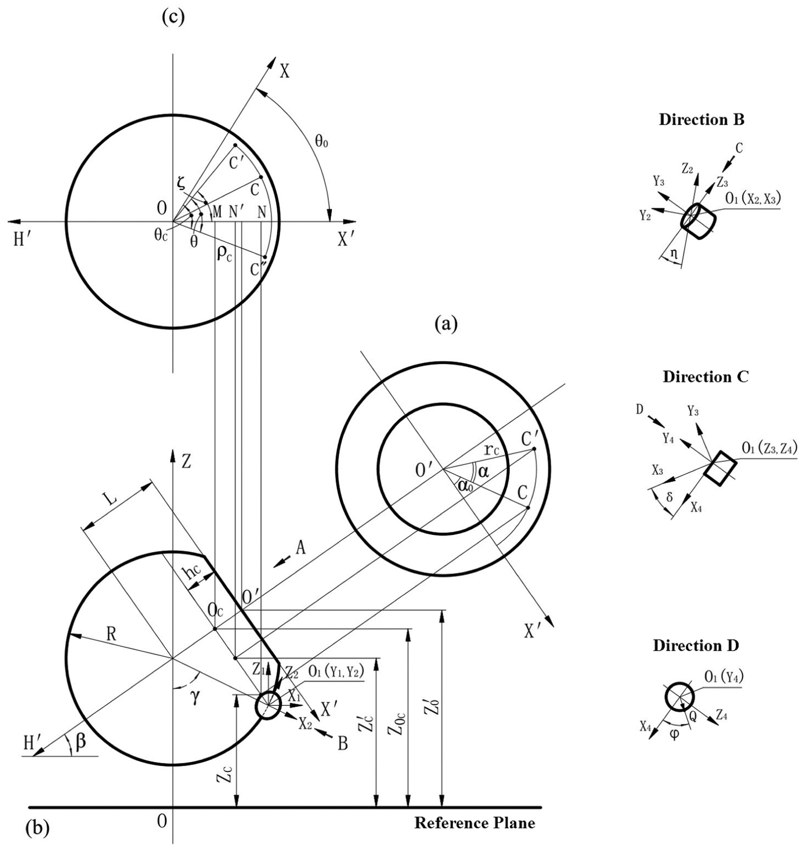
Geometry of single-roller PDC bit: (a) view from direction A for the back cone plane of roller, (b) front view of single roller, and (c) top view in addition to (b).
Set up four rectangular coordinate systems for PDC cutters and respectively from the center points of four cutters. 15 Set up a coordinate system O1X1Y1Z1 for the position of PDC cutters, to make O1Z1//OZ and pointing to the same direction as OZ, and O1X1 in a horizontal direction and perpendicular to OZ. Rotate O1X1Y1Z1 around O1Y1 by an angle γ (the included angle between the reference line of cutter and the axis of bit) in the clockwise direction to obtain a coordinate system O1X2Y2Z2, to make O1X2 collinear with the reference line of cutter and pointing to the external of bit. Rotate O1X2Y2Z2 around O1X2 by η in the clockwise direction to obtain a coordinate system O1X3Y3Z3, to make O1X3 collinear with the reference line of cutter and pointing to the direction against from the center line of bit (coinciding with O1X3). Rotate O1X3Y3Z3 around O1Z3 by δ in the counterclockwise direction to obtain a coordinate system O1X4Y4Z4, to make O1Z4 perpendicular to the directional reference line of PDC cutter (coinciding with O1Z3).
In consideration of expressing all geometrical features of a cutter, such as points, lines, and planes, define the parameter equations for the blade curves of the cutter as follows

wherein rQ is radius of PDC cutter.
According to the principles for transformation of rectangular coordinate system, obtain the equations for the position coordinates for the blade profile of PDC cutter as follows

Geometrical equations for describing motion of PDC cutters
During operation, the motion of a single-roller bit consists of rotation and displacement, which are for the convenience of study analyzed in separation before combination of them.
Rotation of roller
Relative rotation of roller around roller shaft
Assume that the bit does not rotate, and the roller rotates around the roller shaft. Define the center point on a surface of PDC cutter as the characteristic point C (ρ, θ, Z) and the initial position as α0. After a time lapse t, point C moves to point C′ and arrives at a position angle α0 + α. Each view in Figure 3 includes the point C′ and its projection.
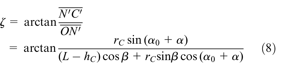
The true length is indicated as the distance between O and C′ to represent the radius vector of point C′ in the top view. OC′ constitutes the oblique side of the right triangle ΔON′C′, of which the right angle sides ON′ and N′C′ are as follows


wherein L is the distance from the center of spherical roller to the back cone plane of roller; hC is the vertical height of point C, the center point on the surface of PDC cutter, in the dynamic coordinate system; rC is the radius of the characteristic circle in which the characteristic point lies; α0 is the initial rotation angle of roller with respect to the roller shaft; α is the rotation angle of roller with respect to the roller shaft, wherein

Subject to the time lapse t, calculate the radius vector ρQ of a point Q on the blade profile of cutter as follows

Rotation of roller and roller shaft around the center axis of bit
Under the assumption that only the bit rotates, and the roller does not rotate around the roller shaft, point C′ conducts fixed-axis rotation around the center axis of bit, and, after the time lapse t, point C′ moves to point C″ after traveling over the angle θ, as shown in Figure 3. The true value is reflected in the top view for the polar angle θC″ of the characteristic point C″, and θC″ is the sum of the polar angle of point O′ and ∠N′OC″, wherein

Accordingly, subject to the time lapse t, calculate the polar angle θQ of a point Q on the blade profile of cutter as follows

Displacement of roller
During operation, the roller moves along the center axis of bit in addition to rotation. The true length is reflected in Figure 3(b) for the net vertical height ZC′ of the characteristic point C after time t. Define the difference between ZC′ and the vertical height ZOC of the center of characteristic circle as follows

Define the difference between ZOC and the vertical height ZO′ of origin O′ as follows

Accordingly, subject to the time lapse t, calculate the vertical height ZQ of a point Q on the blade profile of cutter as follows

Equations (6), (9), and (12) are motion geometrical equations of single-roller PDC bit.
Velocity of PDC cutter on roller
To facilitate the study on the velocity and acceleration of a single-roller PDC bit, regard the absolute motion of point Q on the PDC cutter of single roller, according to the new viewpoints from the analysis based on the modern kinematics of roller bit, as the combination of the following three motions: radial relative motion, which means the radial motion of point Q, expressed in the radius vector ρQ at the velocity vQρ; tangential translational motion, which means the tangential rotation of point Q around the center axis of bit, expressed in the polar angle θQ at the angular velocity ωQ; and longitudinal translational motion, which means the longitudinal motion of point Q, expressed in ZQ at the velocity vQZ, provided that the directions of these three motions are 90° to each other.
Accordingly, based on the geometrical equations for the motions of a single-roller bit, establish the basic equations for the velocity of a point on the PDC cutter of single roller, to obtain the radial component velocity vQρ, tangential component velocity vQτ, and longitudinal component velocity vQZ of point Q as follows


Accordingly, express the absolute velocity vQ of point Q as

Radial component velocity
Calculate the derivative of time in equation (6), and define ω2 as the rotation velocity of roller, to obtain the radial component velocity vQρ of point Q

wherein

Tangential component velocity
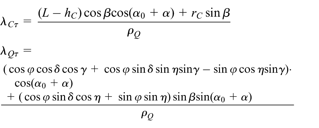
Calculate the derivative of time in equation (11), and define ω1 as the rotation velocity of bit, to obtain the tangential component velocity vQτ of point Q

wherein
Longitudinal component velocity
Calculate the derivative of time in equation (14), and define vZ as the longitudinal velocity of bit, to obtain the longitudinal component velocity vQZ of point Q

wherein

Example and analysis
To further understand the level of influences on the velocity by the parameters of single-roller PDC bit, a quantitative analysis is made herein on the velocity of the single roller with PDC cutters, based on certain parameters given in Deng et al. 9 and the relevant geometrical parameters designed herein for the single-roller PDC bit, to determine the rules of the velocity changing along with other parameters, which are given as follows: L = 30 mm; R = 50 mm, hc = 40 mm, β = 50°, α = 30°, η = 5°, δ = 38°, rQ = 6.72 mm, ω1 = 60 r/min, and transmission ratio i = 0.748 (limestone).
The relationship between the roller speed and the bit rotation speed is the transmission ratio. The transmission ratio of the single-roller bit is not only related to the shaft inclination angle but also related to the rock properties and the tooth surface structure. Upon the analysis and summary on the laboratory data given in Deng et al. 16 for the transmission ratio of the spherical single-roller bit, obtain the empirical equation for the transmission ratio i

wherein σ0 is the uniaxial compressive strength of limestone, σ0 = 124 MPa; σ is the uniaxial compressive strength of a rock, MPa.
The results of simulation for the velocity of single-roller PDC bit are shown in Figures 4–9. According to Figure 4, little influence is generated by the front inclination angle δ on the radial component velocity vQρ and absolute velocity vQ; the tangential component velocity vQτ is increasing along with the increase in δ and changes from a negative value to a positive value, wherein, the positive value of vQτ indicates the forward sliding of PDC cutter, and the negative value indicates the backward sliding of PDC cutter; it is obvious that the tangential component velocity has a zero point (vQτ = 0) when equation is found in the absolute values of the two terms to the right of equation (18), namely the tangential component velocity vQτ of point Q at this time point, indicating that the point Q is a pure rolling point at this time point; and the longitudinal component velocity vQZ is irrelative to δ. In Figure 5, it can be found that vQρ, vQτ, and vQ increase, but only by a little, along with the increase in the radius rQ of PDC cutter; and vQZ is irrelative to rQ. In Figure 6, vQρ decreases along with the increase in lateral rotation angle η; vQτ increases along with the increase in η; vQ increases by a little along with the increase in η; and vQZ is irrelative to η.

Change of velocity along with front inclination angle.

Change of velocity along with PDC cutter radius.
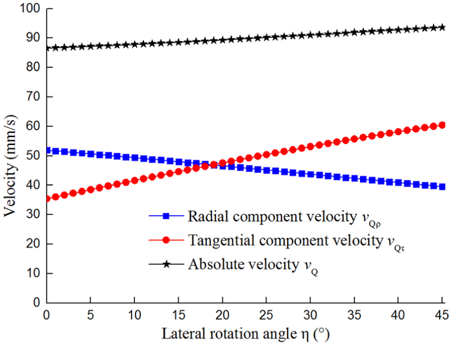
Change of velocity along with lateral rotation angle.
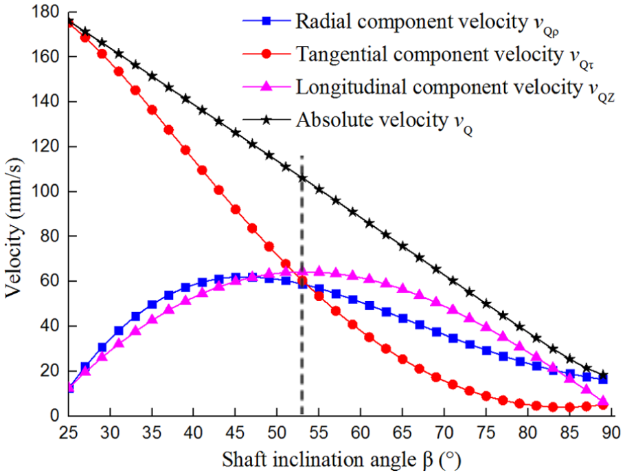
Change of velocity along with shaft inclination angle.
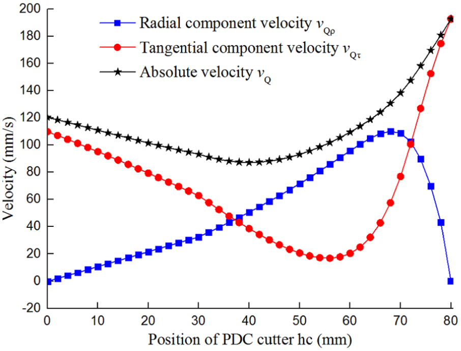
Change of velocity along with height of PDC cutter.

Change of absolute velocity along with height of PDC cutter (limestone).
According to Figure 7, the shaft inclination angle β has high influence on the velocity, wherein vQ and vQτ decrease along with the increase in β; vQρ and vQZ increase and then decrease along with the increase in β; and therefore, in order to reduce the wear of PDC cutter due to over high velocity, it is suggested to design the shaft inclination angle larger than 53° (to the right of the dotted line in Figure 7). According to Figure 8, the height hc of PDC cutter has high influence on the velocity, which indicates that the targets of even wear and equal service life for the cutters are not achieved when β = 60° because the velocities of the PDC cutters vary in different positions on the roller, wherein vQρ increases, during the increase in hc, from zero to the peak and then decreases drastically to zero, but it can be inferred from the structure of single-roller bit that two end points, at which vQρ is zero resulting from hc, do not exist, because that it is impossible to arrange cutters on the positions close to the cone plane of roller, while the water hole of bit occupies the top of roller; vQτ decreases and then increases along with the increase in hc; and vQ slowly decreases and then continuously increases along with the increase in hc.
Select limestone (σ = 124 MPa), sandstone (σ = 33.44 MPa), and granite (σ = 236 MPa) to conduct the quantitative analysis and calculation on the absolute velocity of the PDC cutters of single-roller bit upon equation (20), and the results as shown in Figures 9–11 indicate that the rock stratum has a certain influence on the velocity of cutter, since the transmission ratio of roller varies in the rock stratums with different hardness; in addition, the velocity of cutter is higher in the sandstone than in the granite; in all kinds of rock stratums, the absolute velocity of the most cutters on the roller become smooth along with the increase in shaft inclination angle β, but the absolute velocity of cutters close to the top of roller will increase greatly to cause the drastic wear of cutters, so that it is suggested to pay more attention to the arrangement of cutters within the area to the right of the dotted line in Figures 9–11. When the shaft inclination angle β becomes larger, all component velocities will decrease, and the absolute velocities of cutters in different positions will become more identical, but an over low velocity means the impairment of the interaction between the rock and PDC cutters, resulting in the low efficiency of rock breaking; simultaneously, when the shaft inclination angle β becomes larger, the roller will get close to its vertical position, where the single-roller bit will lose its unique rock breaking feature, and the transmission ratio will be close to its peak value to accelerate the wear of roller bearings. As a conclusion, the shaft inclination angle β of a single-roller bit shall not be designed too large, and it is preferred to be within the range of 53°–70°.

Change of absolute velocity along with height of PDC cutter (sandstone).

Change of absolute velocity along with height of PDC cutter (granite).
Conclusion
For the purposes of improving the adaptability of single-roller bit to the stratum with high hardness and abrasiveness, we designed a spherical single-roller bit based on PDC cutters and established the geometrical equation for the single-roller bit with PDC cutters and the velocity equation for the PDC cutters; got the change rules between the velocity and other parameters by quantitative analysis. It is shown that the velocity is subject to high influence by the shaft inclination angle and the positions of PDC cutters, but is subject to low influence by the radius, lateral rotation angle, and front inclination angle of PDC cutters.
vQ and vQτ decrease along with the increase in β; vQρ and vQZ increase and then decrease along with the increase in β; in order to reduce the wear of PDC cutter due to over high velocity, the shaft inclination angle is to be designed larger than 53° and is suggested to range from 53° to 70°.
The velocity of cutters can be affected by the rock stratum to some extent and is higher in soft rock than in hard rock.
The velocity of PDC cutters varies at different positions on the roller, and the absolute velocity of the most cutters on the roller will become stable along with the increase in the shaft inclination angle, while great increase will be found in the velocity of the cutters near the top of roller, where the distribution of cutters is to be strengthened.
Footnotes
Academic Editor: ZW Zhong
Declaration of conflicting interests
The author(s) declared no potential conflicts of interest with respect to the research, authorship, and/or publication of this article.
Funding
The author(s) disclosed receipt of the following financial support for the research, authorship, and/or publication of this article: This research work was supported by the Southwest Petroleum University Graduate Innovation Fund (Grant No. CX2014BY06) and the China National Ministry of Industry funded project (Researching and Producing of vertical subsea tree) and are gratefully acknowledged.