
Abstract
Micro-milling forces, cutting temperature, and thermal–mechanical coupling are the key research topics about the mechanism of micro-milling nickel-based superalloy Inconel 718. Most current analyses of thermal–mechanical coupling in micro-milling are based on finite element or experimental methods. The simulation is not conducive to revealing the micro-milling mechanism, while the results of experiments are only valid for certain machine tool and workpiece material. Few analytical coupling models of cutting force and cutting temperature during micro-milling process have been proposed. Therefore, the authors studied coupled thermal–mechanical analyses of micro-milling Inconel 718 and presented a revised three-dimensional analytical model of micro-milling forces, which considers the effects of the cutting temperature and the ploughing force caused by the arc of cutting edge during shear-dominant cutting process. Then, an analytical cutting temperature model based on Fourier’s law is presented by regarding the contact area as a moving finite-length heat source. Coupling calculation between micro-milling force model and temperature model through an iterative process is conducted. The novelty is including cutting temperature into micro-milling force model, which simulates the interaction between cutting force and cutting temperature during micro-milling process. The established model predicts both micro-milling force and temperature. Finally, experiments are conducted to verify the accuracy of the proposed analytical method. Based on the coupled thermal–mechanical analyses and experimental results, the authors reveal the effects of cutting parameters on micro-milling forces and temperature.
Introduction
Nickel-based superalloy Inconel 718 has many outstanding properties such as high strength and resistance to oxidation, gas corrosion, and fatigue under high temperature, which meet the requirements of microstructures or components with high strength under high temperature. However, nickel-based superalloy also has disadvantages such as high plasticity, low thermal conductivity, high sensitivity to strain ratio, severe work hardening, large number of hard spots, and high stickiness to the tool, which lead to high cutting force and temperature, as well as serious tool wear. Therefore, Inconel 718 is a typical difficult-to-machine material. Micro-milling is a feasible machining method for Inconel 718. In micro-milling process, a phenomenon related to the minimum cutting thickness happens, which causes cutting forces to vary dynamically. In addition, relative motion between tool and workpiece will lead to the changes of stress distribution and friction heat on contact surface. The heat caused by both plastic strain and friction affects temperature field. Temperature field, in return, affects mechanical properties of the material. The changes of mechanical properties then lead to the change of cutting forces. Therefore, micro-milling is a typical thermal–mechanical coupling process.
Many researchers have established prediction models of micro-milling forces from different aspects. Vogler et al. 1 established micro-milling force model considering the influence of multiphase materials anisotropy. Vogler et al. then predicted the cutting force by a slip-line plasticity force model when the chip thickness is larger than the minimum chip thickness. When the chip thickness is smaller than the minimum chip thickness, an elastic deformation force model was used to predict the cutting force. 2 Malekian et al. 3 investigated the mechanistic modeling of micro-milling forces, with consideration of the effects of ploughing, elastic recovery, run-out, and dynamics. Park and Malekian 4 also established the micro-end-milling force model with consideration of the dynamics of the tool, ploughing, and elastic recovery. Kang et al. 5 proposed an analytical mechanistic model of micro-end-milling to predict the cutting force with consideration of the tool–workpiece contact at the flank face. Han et al. determined the components of the cutting force model based on the newly introduced concept of the partial effective rake angle. The model took the actual physical phenomena at the edge of the tool into account. 6 Moreover, Bissacco et al. 7 studied the effects of chip flow direction on micro-cutting force. Zaman et al. 8 solved instantaneous cutting area according to cutting-edge trajectory. They assumed that cutting force was in proportion to cutting area and established three-dimensional (3D) micro-cutting force prediction model. The model neglected arc radius of cutting edge, friction, and temperature. Considering arc radius of cutting, the minimum cutting thickness, and elastic recovery of material, Zhao 9 regarded axial force as a component of tangential force and established micro-cutting force analytical model in three dimension. Moreover, Lai et al. 10 presented studies on mechanisms of micro-scale milling operation focusing on its characteristics, size effect, micro cutter edge radius, and minimum chip thickness using finite element model. Wu and Liu 11 developed an analytical model to predict the minimum chip based on the strain gradient plasticity theory. Srinivasa and Shunmugam 12 developed a mechanistic model to predict the cutting forces in micro-end-milling operation taking into account overlapping tooth engagements. Ravi and Karali 13 discussed the micro-scale machining issues such as size effect, minimum chip thickness effect, microstructure effects, and cutting tool dynamics which influence the underlying cutting mechanisms and reviewed the recent advances in modeling techniques. Moges et al. 14 incorporated process characteristics such as edge radius of cutting tool, effective rake and clearance angles, minimum chip thickness, and elastic recovery of work material collectively and realized the prediction of cutting forces using mechanistic model. Lu et al. 15 established micro-milling dynamic cutting force prediction model of nickel-based superalloy considering trochoid trajectory of cutter tooth, tool run-out and elastic recovery of machined surface. Oliaei and Karpat 16 studied the influence of tool wear on micro-milling forces and found that the forces were affected by the tool wear patterns. Xiaohong Lu et al. 17 developed a micro-milling force model considering tool flank wear effect obtained by a 3D thermal–mechanical coupled simulation model during micro-milling of nickel-based superalloy. Jie Yi et al. 18 developed a novel micro-flank milling force model by considering the deflection of tool and workpiece, tool run-out, and material strengthening effects during the flank milling of thin-walled parts. Wanqun et al. 19 established an uncut chip thickness including the precise trochoidal trajectory of the cutting edge, tool run-out, and dynamic modulation caused by the machine tool system vibration and developed an improved cutting force model of micro-milling by full consideration of the ploughing effect and elastic recovery of the workpiece material. Emel Kuram and Babur Ozcelik 20 determined the regression models using Taguchi experimental design method with two kinds of aerospace materials (titanium and nickel-based superalloy). Similarly, Zhiqiang Liu et al. 21 established a preliminary relationship of cutting parameters with micro-milling force and milling temperature to discuss the effects of cutting parameters on the micro-milling force and temperature. Rinku K. Mittal et al. 22 found that high-speed micro-milling of Ti6Al4V generates high temperature in cutting zone and leads to a variation in cutting force. Almost none of the above models have taken micro-milling temperature into account. Since micro-milling is a thermal–mechanical coupling process, neglecting cutting temperature will undoubtedly decrease the accuracy of the predicted cutting force.
Most current studies of thermal–mechanical coupling in micro-milling are based on finite element analysis and have made a lot of achievements. Mamedov and Lazoglu established 3D finite element model of Ti-6Al-4V titanium alloy to predict temperature fields of the micro-milling tool as well as workpiece. They verified the model by measuring cutting temperature through thermocouples. 23 Thepsonthi and Özel 24 established finite element models and tracked cutting temperature as well as force during the micro-milling process of Ti-6Al-4V with both uncoated micro-cutting tool and the tool coated by cubic boron nitride (cBN). Ding et al. 25 established a two-dimensional (2D) micro-milling model in ABAQUS and predicted cutting temperature and force. Zhang et al. took the tool wear as the change in tool radius and established 2D finite element model in ABAQUS. They studied how tool wear affects micro-milling temperature field and drew a conclusion that with the tool wear aggravates, the temperatures increase in first, second, third, and fourth temperature areas on workpiece. 26 Lu et al. 27 established micro-cutting finite element model, and the simulation results considering strain gradient effect were closer to the practical values. However, the micro-milling thermal–mechanical coupling analysis based on finite element analyses is not conducive to reveal the micro-milling mechanism.
Experimental method is also used widely to study the changes in cutting temperature and force during micro-milling. Oberschmidt and Uhlmann 28 studied the change rules of cutting force and temperature in micro-milling of monocrystalline diamond. The experimental results showed that the minimum cutting force occurs when the cutting speed is 75 m/min. Bagavathiappan et al. 29 used infrared thermography to monitor the temperature of micro-milling tool and studied the effects of spindle speed, feed rate, and cutting depth on the temperature of micro-milling tool with the workpiece material of aluminum alloy Al6061 and AISI4340 steel. Yang et al. measured temperature field in micro-milling of aeronautic duralumin. Comparing with traditional milling, the cutting temperature was lower. In addition, feed rate had more influences on milling temperature than spindle speed and cutting depth. 30 The experimental method provides direct measurements, and these results are not universal under different machine tools and workpiece material.
When the finite element method is applied to micro-milling field, a large number of meshes are necessary to acquire reliable results. Therefore, the finite element method normally takes huge computation time. Although experimental method is able to predict cutting force by statistics, it does not reveal inherent mechanism of micro-milling. Therefore, it is necessary to establish a micro-milling force analytical model considering cutting temperature. Through the thermal–mechanical coupling calculation, the accurate and efficient prediction of micro-milling force and temperature is realized.
This article mainly presents the coupled thermal–mechanical analyses of micro-milling Inconel 718. First, a revised 3D micro-milling forces model is built based on the model of the instantaneous undeformed chip thickness established earlier. The revised force model takes the effect of ploughing caused by cutting-edge arc into account during shear-dominant region cutting process, and more importantly, the presented prediction model also considers the effect of the cutting temperature. Then, by regarding the contact area as a moving finite-length heat source, an analytical cutting temperature model based on Fourier’s law is presented. Therefore, the coupling calculation between micro-milling forces model and temperature model through the iterative process is conducted. Finally, experiments are conducted to verify the accuracy of the proposed analytical method. Based on the coupled thermal–mechanical analyses and experimental results, the authors reveal the effects of cutting parameters on micro-milling forces and temperature. The established model explores the micro-milling mechanism and lays a foundation for further research on work hardening.
Prediction model of micro-milling forces
When actual cutting thickness is larger than the minimum cutting thickness during micro-end milling, the cutting layer is under plastic deformation as shear slipping. Chips are then formed, namely, shear-dominant cutting process. When the actual cutting thickness is smaller than the minimum cutting thickness, the cutting layer, after being ironed by cutting edge, slips off flank surface of tool. In this case, only elastic deformation occurs without any chip, which is called ploughing-dominant cutting process. The minimum cutting thickness is used as the classification standard in micro-milling process.
The minimum cutting thickness can be obtained through experimental method, finite element method, and elastic–plastic theory method. In this article, the minimum cutting thickness value (tmin = 0.7 μm) is acquired by research group earlier. 15 The minimum cutting thickness tmin is the boundary. When the cutting thickness tc is larger than tmin, cutting force prediction model during shear-dominant cutting process is applied to predict cutting force. When the cutting thickness tc is smaller than tmin, cutting force prediction model during ploughing-dominant cutting process is chosen. The process of establishing these two models is described as follows.
Cutting force prediction model during shear-dominant cutting process
When cutting thickness tc is larger than the minimum cutting thickness tmin, chips are cut down from the workpeice. In this case, shear effect is dominant. Compared with traditional milling, in the micro-milling force model, the effect of cutting-edge arc cannot be ignored because the cutting thickness and the arc radius of cutting edge are at the same size level. Therefore, during shear-dominant cutting process, cutting force is divided into shear force (shear_Fs) and ploughing force (shear_Fp). Shear force causes the formation of chips, and ploughing force is caused by the cutting-edge arc. Cutting force during shear-dominant cutting process is obtained by combining these two parts.
Shear force (shear_Fs) during shear-dominant cutting process
Assuming the shear tress on primary shear plane is uniformly distributed and taking helix angle into account, tangential force (shear_Fsc), radial force (shear_Fsr), and axial force (shear_Fsa) are expressed as equation (1) according to the research of Chen 31
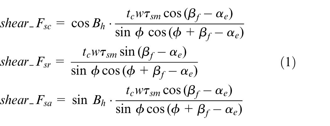
where Bh is the helix angle of the tool with a value of 30°. tc (mm) is the cutting thickness. w (mm) is the cutting width. τsm (MPa) is the shear stress on primary shear plane. Φ is the shear plane angle. βf is the friction angle between tool and chips. αe is the effective rake angle of the tool. These parameters are calculated as follows.
Cutting thickness tc. The actual cutting thickness model cited in this article is established by research group. 32 The actual cutting thickness at moment t is expressed as follows
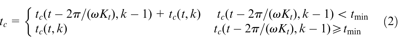
where k is the number of cutting edge, k = 0, 1, 2, …, Kt −1, and Kt is the total number of cutting edge. In this research, Kt = 2. ω (rad/s) is the rotation angular speed of tool. tc (t, k) is the cutting thickness of kth tooth at moment t. tc (t, k) is calculated according to equation (3)
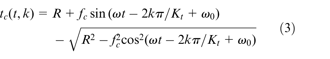
where
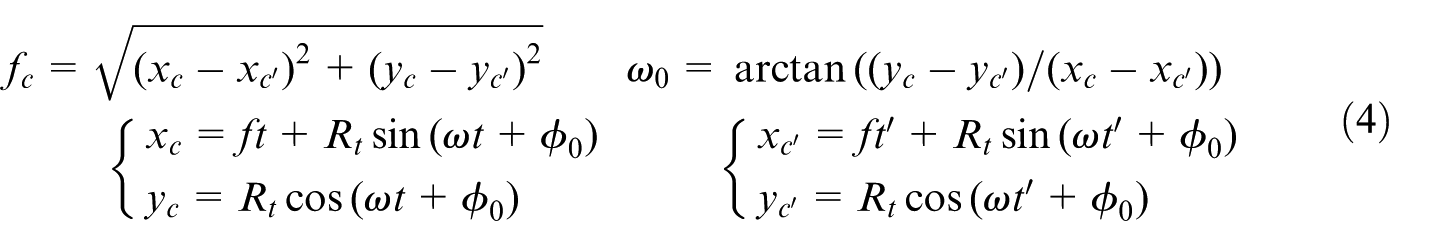
R (mm) is the radius of micro-milling tool. Rt (mm) is the radical run-out of cutting edge. f (mm/s) is the feed rate. φ0 is the initial angle of the radial run-out of the cutting edge, which is π/3. t and t’ in equation (4) are decided according to the following theory.
First, the criterion whether single tooth cutting effect occurs or not is shown in equation (5)
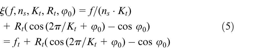
where ns (r/min) is the spindle speed and ft (mm/z) is the feed per tooth. The rest of parameters are consistent with the previous ones. When the cutting parameters meet the condition of ξ (f, ns, Kt, Rt, φ0) < 0, the single tooth cutting effect occurs and t’ is calculated by equation (6). When ξ (f, ns, Kt, Rt, φ0) ≥ 0, alternate multi-tooth cutting occurs and t’ is calculated by equation (7)
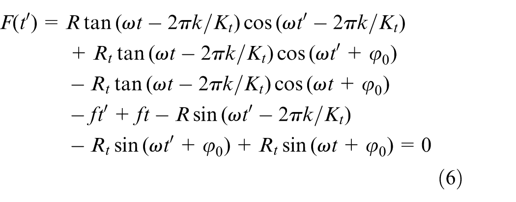
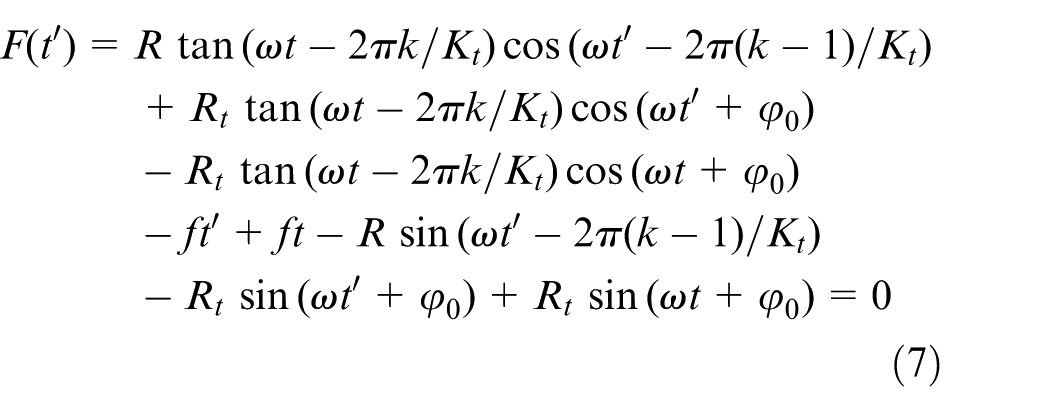
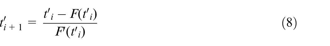
Nonlinear equations (6) and (7) are solved by Newton–Raphson iterative algorithm. The iteration is realized by equation (8)
where
Cutting width w. The helix angle of the tool used in this research is 30°, so the cutting width w is approximately equal to ap/cos 30°, where ap (mm) is the axial cutting depth.
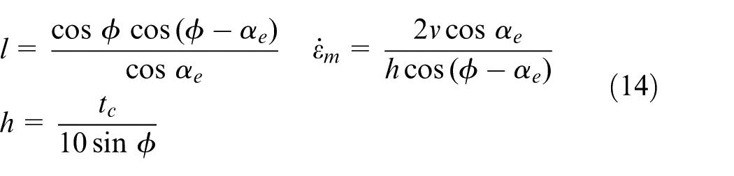
Shear plane angle Φ. The shear plane angle Φ is determined by Merchant Equation as shown in equation (9)
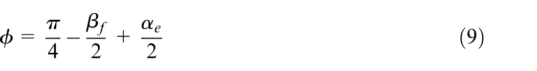
where βf is the friction angle decided by friction characteristics on the tool–workpiece interface. αe is the effective rake angle of the tool, which varies with the change in actual cutting thickness and is expressed as equation (10) according to the geometrical relationship as shown in Figure 1
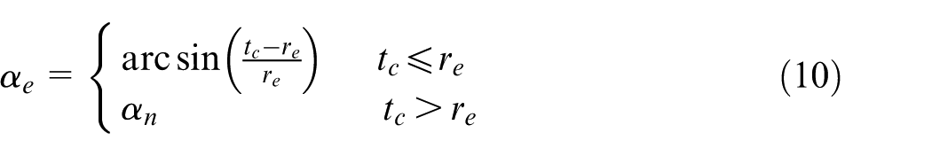
where tc (mm) is the cutting thickness; re is the arc radius of cutting edge, which is 0.002 mm; and αn is the nominal rake angle of the tool which is
Shear stress τs in primary shear zone and shear stress τsm on primary shear plane
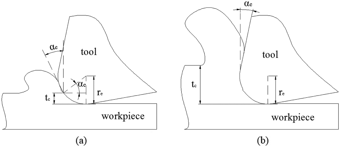
Effective rake angle of the tool: (a) tc ≤ re and (b) tc > re.
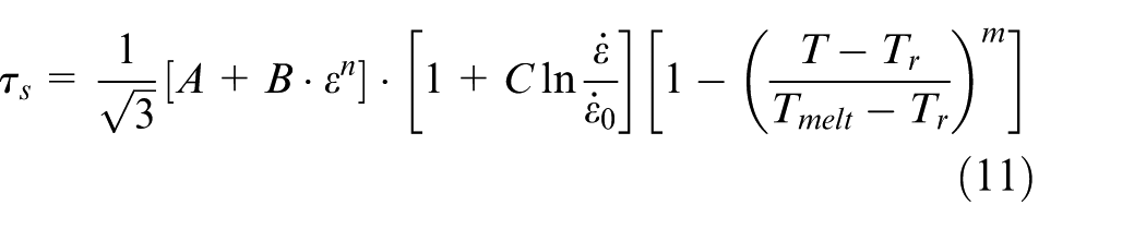
Based on Johnson–Cook constitutive model, shear stress in primary shear zone 33 is expressed as equation (11)
where
According to Li et al.,
35
the calculations of shearing strain rate
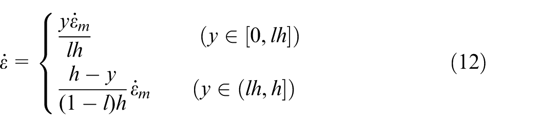
where v is the cutting speed with a unit of meter/second
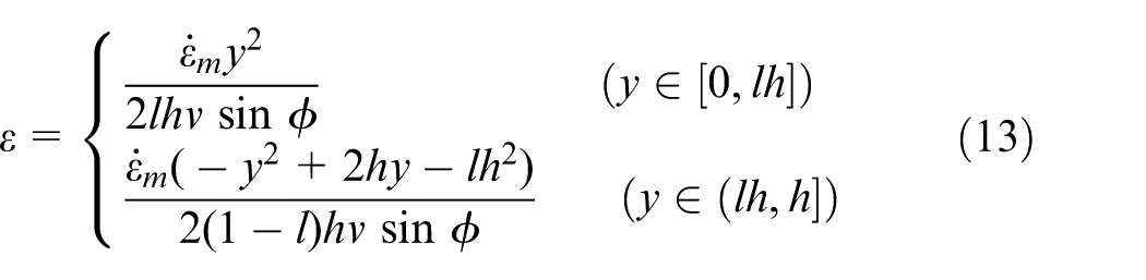
when y = lh, shearing strain
Shear stress τs in primary shear zone is expressed by substituting parameters into equation (2). In addition, melting temperature of Inconel 718, shearing strain rate
Ploughing force (shear_Fp) during shear-dominant cutting process
In micro-milling process, the cutting thickness is in micrometer level. The arc radius of cutting edge is at micron level too (in this research, the arc radius of cutting edge is 2 μm). Therefore, the ploughing effect caused by cutting-edge arc is included. In this article, when cutting thickness is larger than the minimum cutting thickness, the ploughing force caused by cutting-edge arc is acquired according to the slip-line field model proposed by Waldorf et al. 36 as shown in Figure 2.
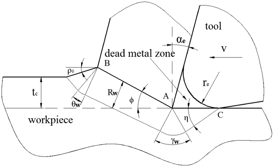
Slip-line field model proposed by Waldorf.
In Figure 2, tc is the cutting thickness. ρ0 is the slope angle of transitional slope between chip and surface of workpiece, which is 30° in this research. Φ is the shear plane angle determined by equation (9). αe is the effective rake angle of the tool determined by equation (10). re is the arc radius of cutting edge which is 0.002 mm. According to the theory of Dewhurst and Collins, 37 the angle between slip line and the bottom of dead metal zone AC is expressed as

where μ is the friction factor, which is 0.4 in the research of Sharman et al. 38 The central angle of the sector region with center point A is as follows
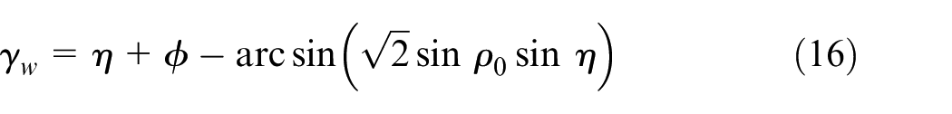
The central angle of the sector region with center point B is
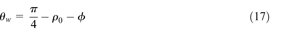
The radius of the two sectors with center point A and B is
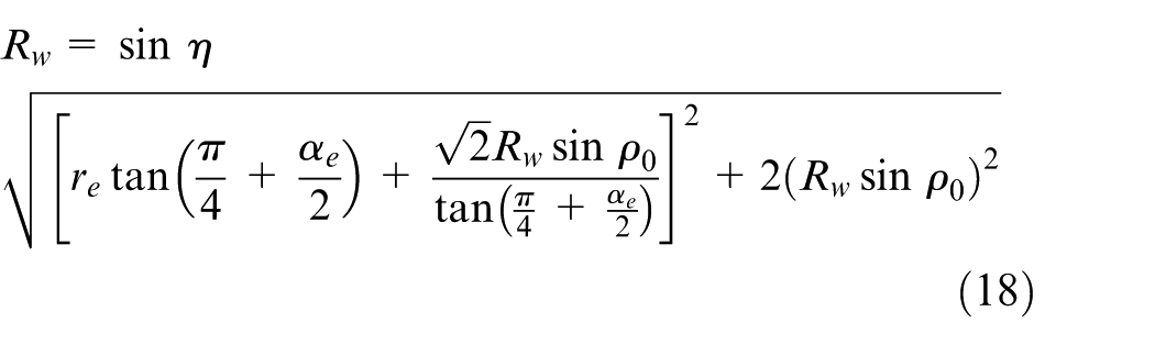
The length of the bottom of dead metal zone AC is
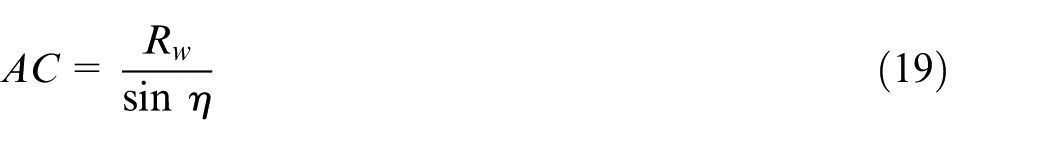
Based on the theory of Waldorf, 36 the ploughing force caused by cutting-edge arc is obtained by equation (20)
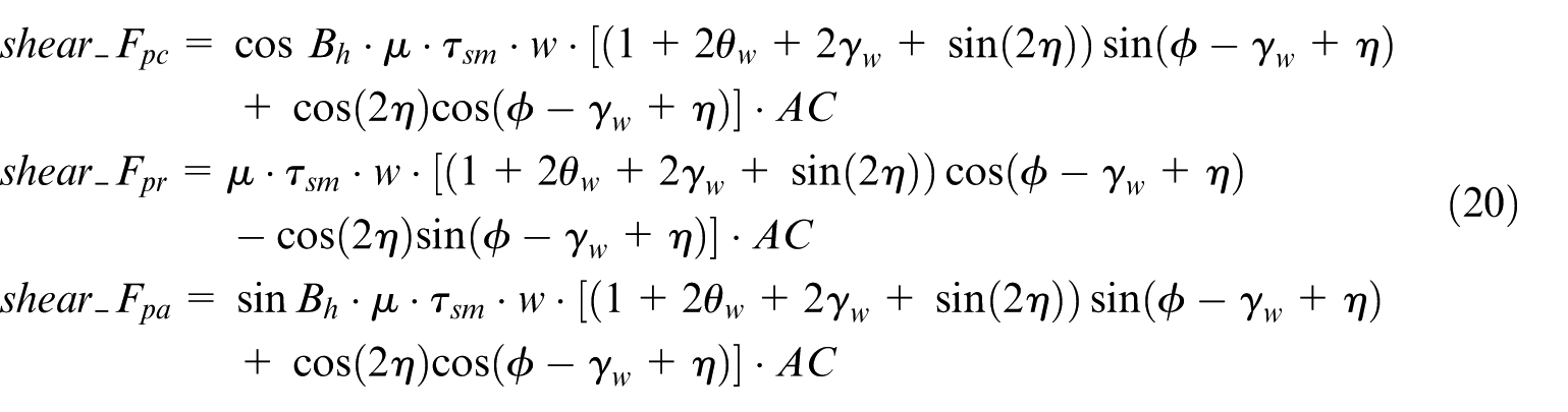
In equation (20), shear_Fpc is the tangential component of ploughing force during shear-dominant cutting process, shear_Fpr is the radial component of ploughing force during shear-dominant cutting process, and shear_Fpa is the axial component of ploughing force during shear-dominant cutting process.
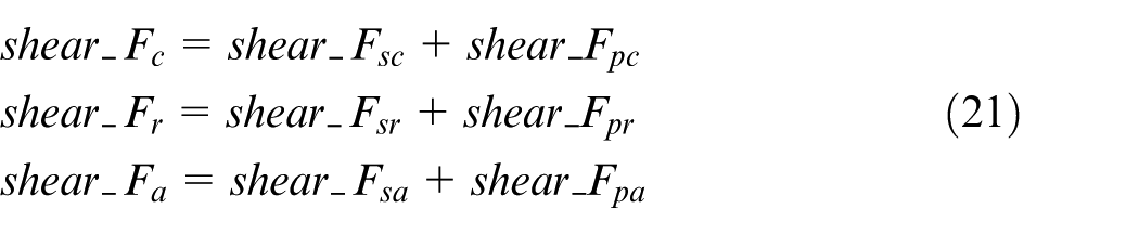
Integrating the contents of part (1) and part (2), the cutting force (shear_F) during shear-dominant cutting process is the sum of shear force (shear_Fs) and ploughing force (shear_Fp) as shown in equation (21)
Cutting force prediction model during ploughing-dominant cutting process
According to the previous research, 15 when the cutting thickness is smaller than the minimum cutting thickness, the ploughing force is expressed as equation (22). The ploughing force is proportional to interference volume
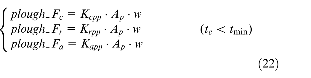
where w (mm) is the cutting width acquired in subsection “Shear force (shear_Fs) during shear-dominant cutting process.”Kcpp, Krpp, and Kapp are the tangential, radial, and axial coefficients of ploughing effect with a unit of Newton/cubic millimeter, and Ap is the interference area with a unit of square millimeter.
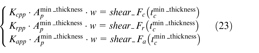
In the micro-milling process, the cutting thickness varies between zero and the maximum cutting thickness which is related to feed per tooth and some other factors. With the change in cutting thickness, the deformation mechanism is dominated by ploughing-dominant or shear-dominant cutting process. It is found that the change in cutting force is continuous according to the experimental data. Therefore, when the cutting thickness is exactly the minimum cutting thickness, the cutting force calculated by the model during ploughing-dominant cutting process is equal to the force calculated by the model during shear-dominant cutting process as shown in equation (26). Then, Kcpp, Krpp, and Kapp are obtained
where
Coordinate transformation for micro-milling forces
In the actual measurement of micro-milling force, the cutting forces measured by dynamometer are forces in X, Y, and Z directions instead of in tangential, radial, and axial directions. So, it is necessary to convert the coordinates of cutting forces to validate the established model. The transformation can be achieved by equation (24)
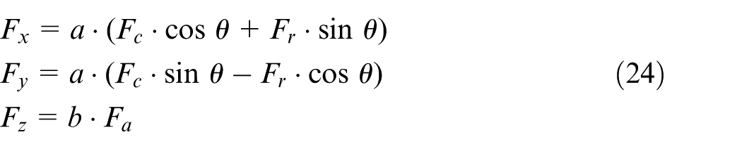
where
The actual cutting process is quite complex and influenced by chatter, tool wear, extended length of tool, and so on. So, the empirical coefficients a and b are added to predict the cutting force accurately. The values of a and b are calculated in the following section.
Prediction model of cutting temperature
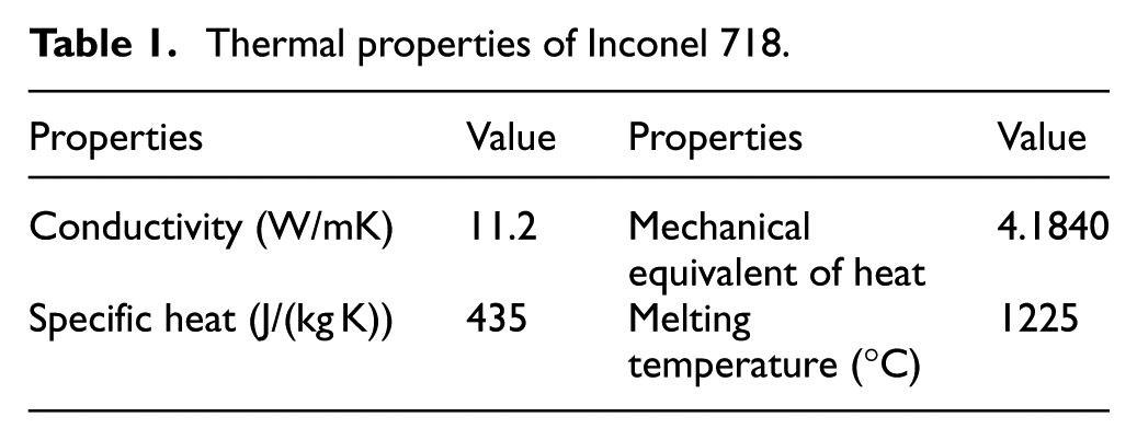
The modeling of micro-milling temperature is based on Fourier’s law. The thermal properties of Inconel 718 used in this model are shown in Table 1.
Thermal properties of Inconel 718.
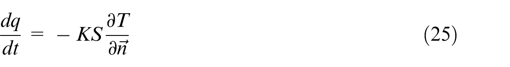
As described in Fourier’s law, in the process of heat conduction, heat transfer rate through a material per unit time is proportional to the temperature gradient and cross-sectional surface area. And heat flow has the opposite direction as temperature rises as shown in equation (25)
where
The temperature gradient is expressed as equation (26), and the angles between vector
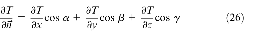
The amount of heat transferred per unit time through the cross-sectional surface area S is expressed as
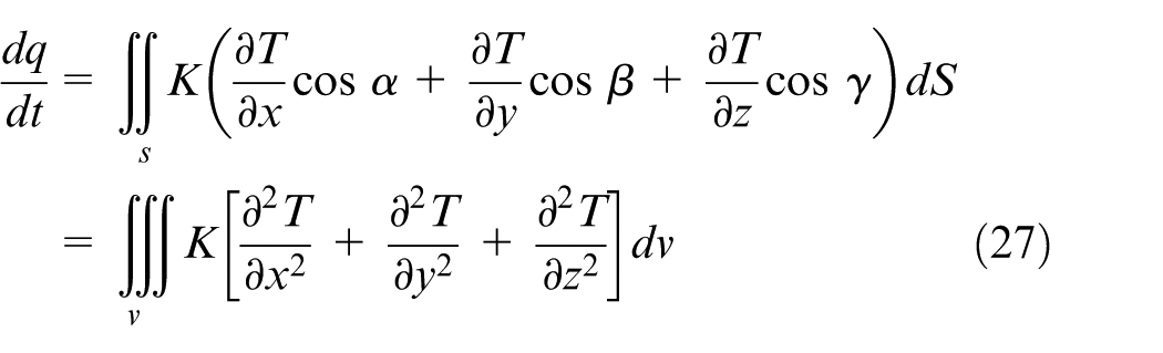
According to the thermodynamic theory, it is also expressed as
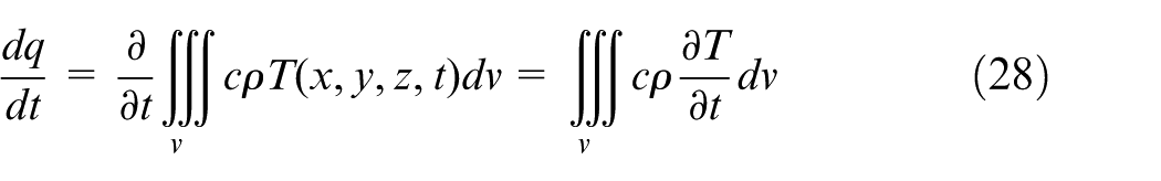
where c is the specific heat of workpiece material with the unit of Joule/(kilogram Kelvin) and ρ is the density of workpiece material with the unit of kilogram/cubic meter.
Combining equations (27) and (28), the following equation (29) is obtained
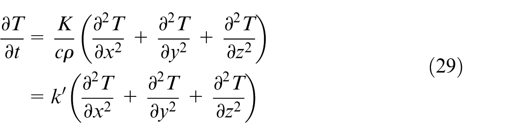
where
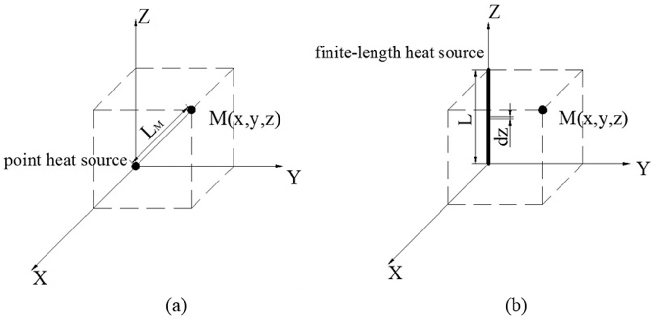
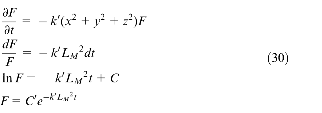
Temperature rise at point M caused by (a) point heat source and (b) finite-length heat source.
Fourier transformation and a series of mathematical transformations conducted on equation (29) are shown in equation (30)
Inverse Fourier transform is conducted on these results
where ΔT (x, y, z, t)
point
is the temperature rise at point M caused by point heat source at the origin. C’ can be worked out according to conservation of energy, that is,
Therefore, when point heat source is at the origin, the rise of the temperature at point M (x, y, z) at moment t is expressed as
When heat source is the finite-length heat source with a length of L as shown in Figure 3(b), the temperature rises at point M (x, y, z) at moment t is expressed as equation (33)
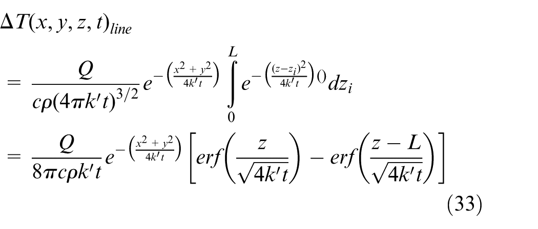
where erf(x) is the Gauss error function
When the heat source is not at the origin, temperature rise at point M caused by finite-length heat source at moment t is
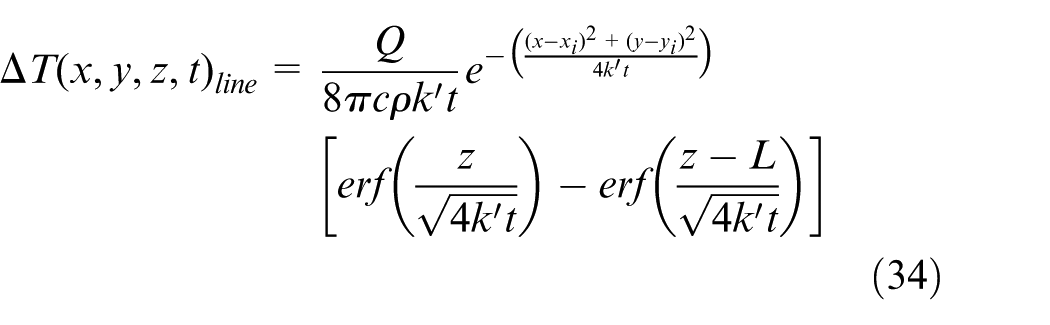
where xi and yi are the horizontal and vertical coordinates of heat source, respectively, with the unit of meter.
In the micro-milling process, each cutting area on a cutting edge is regarded as a moving finite-length heat source as shown in Figure 4. The length of heat source is presented by cutting width approximation with the unit of meter (w = ap/cos 30°). The position of the heat source in micro-milling is
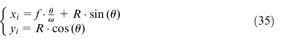
where θ is the cutter tooth position angle defined as the angle between cutter tooth tip and the positive direction of Y-axis with the unit of radian, R is the radius of micro-milling tool with the unit of meter, f (mm/s) is the feed rate, and ω (rad/s) is the rotation angular speed of tool. According to equations (34) and (35), temperature rise at point M (x, y, z) when the workpiece is cut by a single tooth from point A to B in Figure 4 is expressed as
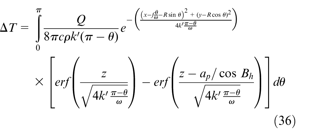
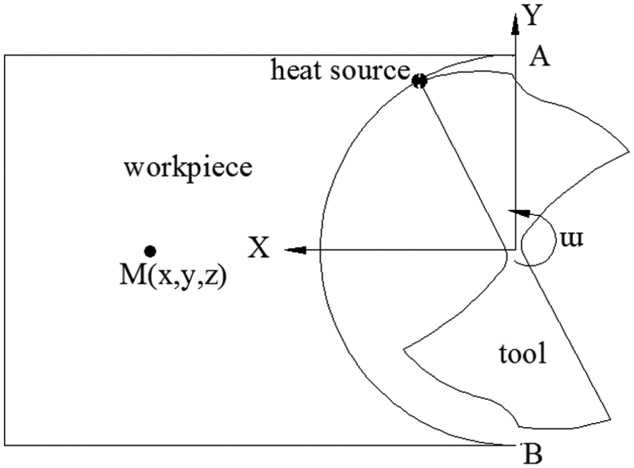
Coordinate system of micro-milling.
Since the final temperature rise at a certain point in workpiece is the accumulation of multiple cuttings, the ultimate temperature rises at point M (x, y, z) is
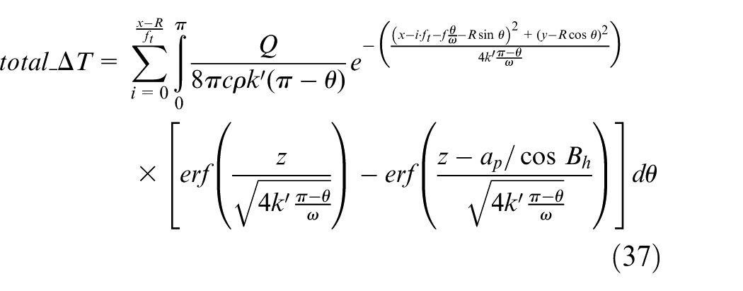
where
According to the research of Zhang, 39 the ratio of cutting heat transferred to the workpiece is
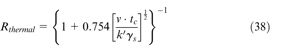
where tc is the cutting thickness with the unit of meter,
Coupled thermal–mechanical analysis
It can be seen that the cutting force is affected by the cutting temperature, as shown in equation (11), and the micro-milling temperature is also affected by the micro-milling force as the calculation of Q in equation (37). Due to the interaction of micro-milling force and temperature, the cutting temperature and micro-milling force are obtained via an iterative calculation. The coupled process is shown in Figure 5.
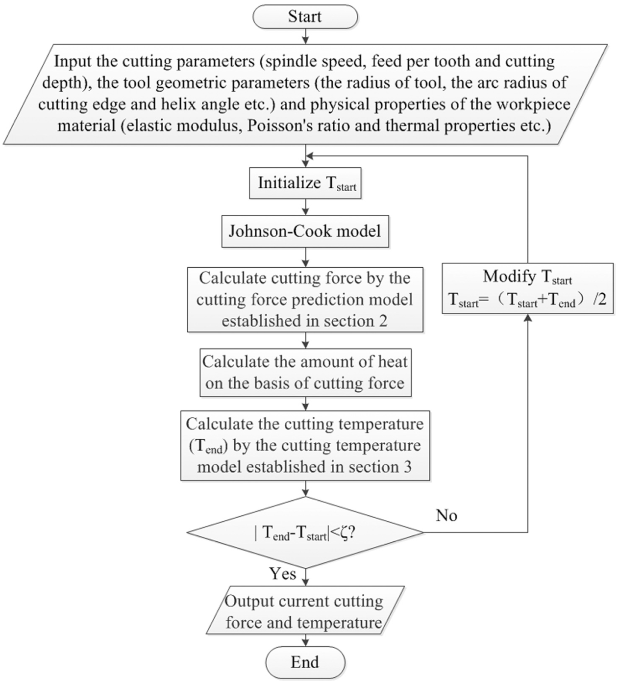
Flowchart of coupled thermal–mechanical calculation.
First, the cutting parameters (including spindle speed, feed per tooth, and cutting depth), the tool geometric parameters (including the radius of tool, the arc radius of cutting edge, and helix angle) and physical properties of the workpiece material (including elastic modulus, Poisson’s ratio, and thermal properties) are given. The initial temperature Tstart is set to room temperature. Then, the corresponding cutting force is calculated. Based on the acquired cutting force, cutting temperature Tend is calculated through the micro-milling temperature model established, and then, Tstart is compared with Tend. ζ (Figure 5) is an artificial value set as 0.5. When the value of ζ is smaller, the result is more accurate, but the computation time is longer. When absolute difference between Tstart and Tend is larger than ζ, Tstart is modified as the mean value of Tstart and Tend. The iterations stop when the difference is smaller than ζ. Then, the cutting forces and temperature are decided.
Determination of empirical coefficients and experimental verification
Experimental condition
Micro-milling slot experiments are conducted on self-developed micro-milling machine. The spindle speed range is from 40,000 to 140,000 r/min. The machine is equipped with Kistler 9256C1, a force signal acquisition system, as shown in Figure 6. During the micro-milling slot experiments, Flir A40 infrared thermography is used to measure micro-milling temperature, as shown in Figure 6. The cutting tools are MSE230, an end milling tool made of ultrafine particle-coated cemented carbide, with two teeth whose diameter is 1 mm and arc radius of cutting edge is 2 μm. The clearance angle is approximately 5°. The workpiece material is Inconel 718.
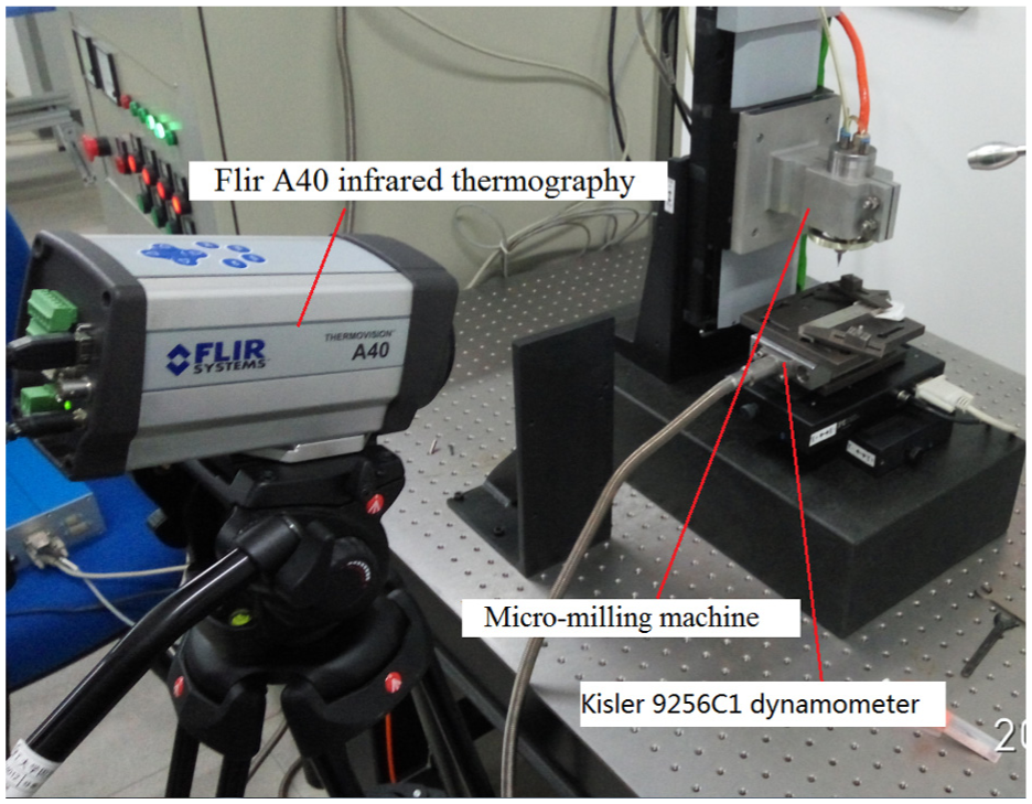
Force acquisition system (Kistler 9256C1) and temperature measurement system (Flir A40).
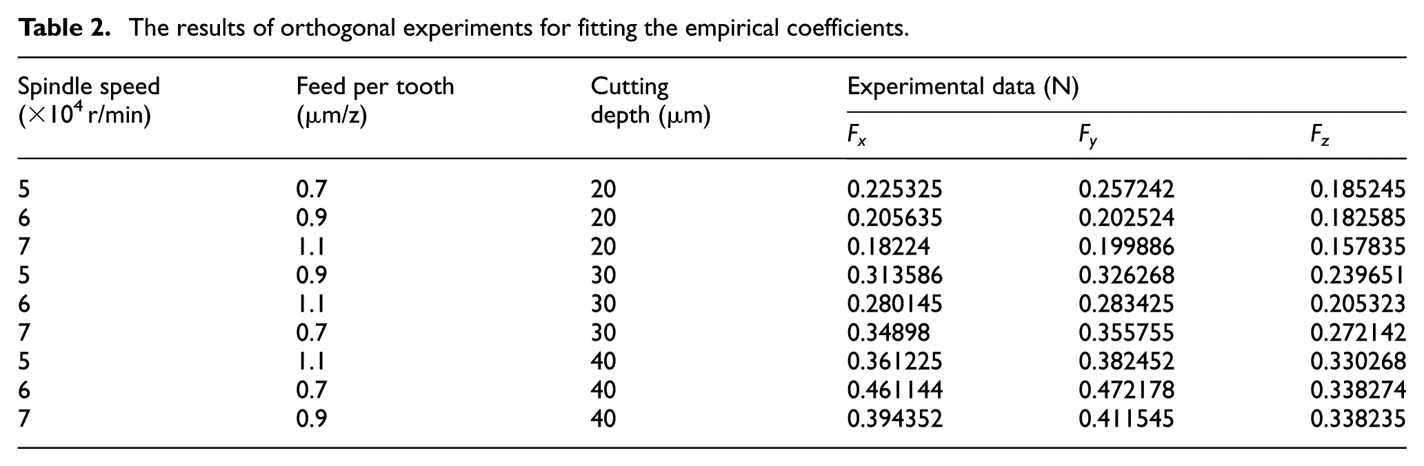
To determine the empirical coefficients a and b in equation (24), orthogonal experiments considering three factors at three levels are conducted. The verification experiment is designed as a single-factor one to verify the models and conclude the influences of cutting parameters on micro-milling force and temperature.
Determination of empirical coefficients a and b
Because the actual cutting is a complicated process, a simplified theoretical model is not enough without empirical coefficients. The empirical coefficients a and b are then included to make the theoretical model more consistent with the actual micro-milling forces as shown in equation (27). In order to get a more accurate result, orthogonal experiments are conducted as shown in Table 2. And the least square method is used to fit the empirical coefficients. The fitting results are a = 0.6409 and b = 1.3544.
The results of orthogonal experiments for fitting the empirical coefficients.
Experimental verification of the proposed force and temperature model
Single-factor experiment is conducted to study the effects of cutting parameters on micro-milling force and temperature. The experimental condition is the same as that mentioned above. During the experiments, the micro-milling forces are collected by Kistler 9256C1 and the cutting temperature is measured by Flir A40 infrared thermography. The experimental results are listed in Table 3.
The results of verification experiment.
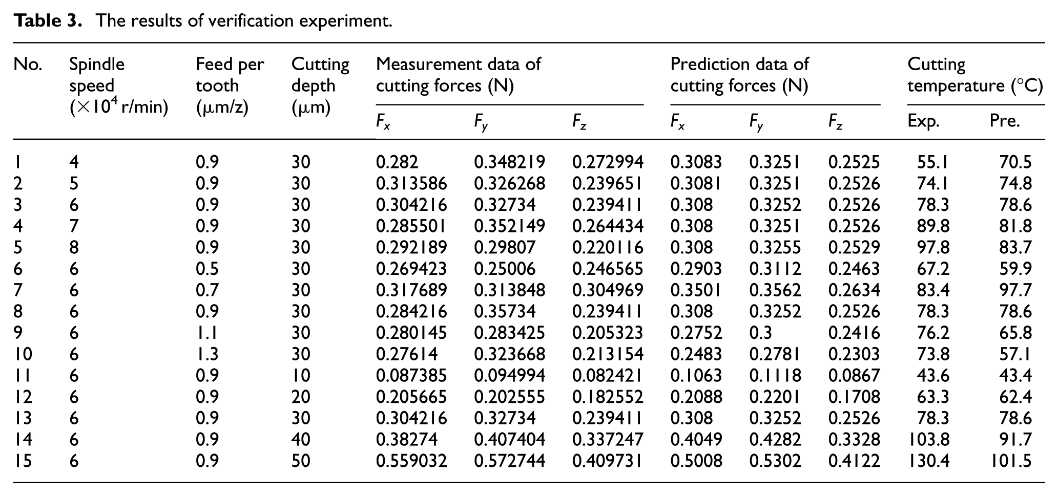
The maximum and mean prediction error of micro-milling force is 24.5% and 7.8%, respectively. The maximum and mean prediction error of cutting temperature is 27% and 10.2%, respectively. Besides the factors mentioned in this article, there are many other factors that affect the micro-milling process, such as chatter stability, inhomogeneous workpiece material, tool wear, and so on. All these factors cause the prediction error. While the results show that change trend and data between the calculation results and the experimental results are similar, and the relative error reached the normal level in this field such as the Wu and Liu’s 11 research, where the average prediction error of micro-cutting force is about 5%. The average prediction error of our model is 7.8%. Considering that the micro-milling process is more complex than orthogonal cutting, the prediction accuracy is acceptable.
The line charts are drawn to intuitively reflect the influences of cutting parameters on micro-milling force and temperature. Each blue point in Figures 7–9 indicates a peak value of the cutting force data obtained by experiments, and the red points are values from model. When processing force data, we take the average value of many peak values as the real peak value. As shown in Figure 7, within the range of the selected cutting parameters, effects of spindle speed on micro-milling forces are not obvious. The increase in spindle speed will not lead to the increase in cutting layer area directly, but increase the strain rate. On one hand, according to Johnson–Cook model, the increase in stain rate will increase shear stress, which leads to the increase in cutting forces. On the other hand, the increase in stain rate will lead to the insufficient strain hardening, which leads to the decrease in cutting forces. Because of the interaction between the two effects, spindle speed has little effect on cutting forces within the range of selected cutting parameters. There is a positive correlation between cutting temperature and spindle speed. The increase in spindle speed has little effect on cutting forces, but will cause the increase in cutting speed and the amount of heat per unit time. As a result, the cutting temperature rises.
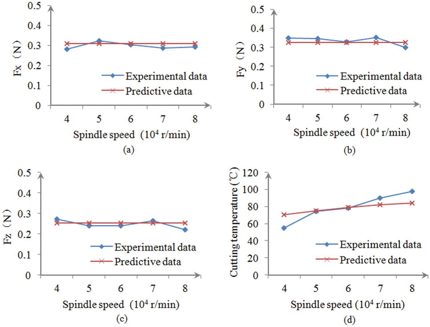
Effect of spindle speed on cutting force and cutting temperature: (a) The influence of spindle speed on Fx, (b) The influence of spindle speed on Fy, (c) The influence of spindle speed on Fz and (d) The influence of spindle speed on cutting temperature.
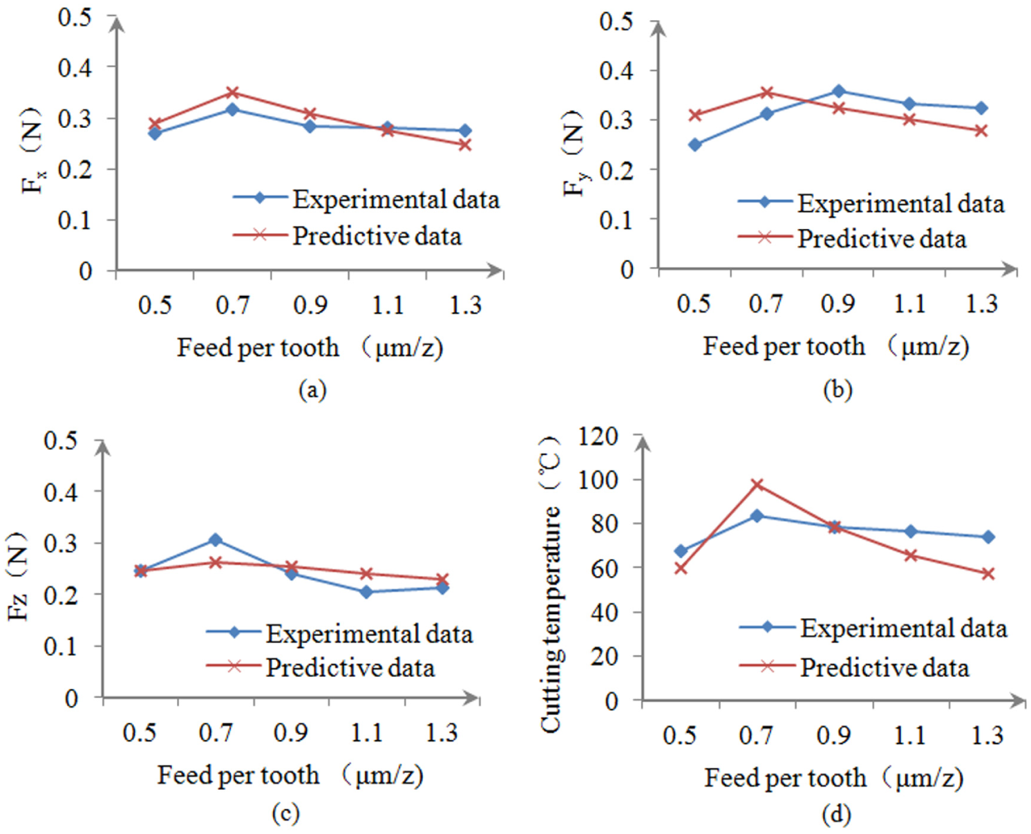
Effect of feed per tooth on cutting force and cutting temperature: (a)The influence of feed per tooth on Fx, (b)The influence of feed per tooth on Fy, (c)The influence of feed per tooth on Fz and (d)The influence of feed per tooth on cutting temperature.
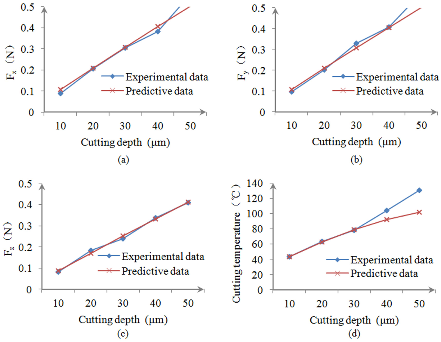
Effect of cutting depth on cutting force and cutting temperature: (a) The influence of cutting depth on Fx, (b) The influence of cutting depth on Fy, (c) The influence of cutting depth on Fz and (d) The influence of cutting depth on cutting temperature.
As shown in Figure 8, within the range of the selected cutting parameters, the cutting force and temperature have a turning point when feed per tooth is about 0.7 μm (the minimum cutting thickness). The cutting force and temperature increase at first and then decrease. When instantaneous cutting thickness is smaller than the minimum cutting thickness, with the increase in feed per tooth, the interference volume will increase, which leads to the increase in cutting forces eventually. When instantaneous cutting thickness is larger than the minimum cutting thickness, the effect of various effective rake angle is dominant, and the cutting forces decrease with the increase in feed per tooth within the range of the elected parameters. It is estimated that the cutting force will increase when the effective rake angle of the tool reaches the nominal rake angle. After that, the change trend will be the same as that of the traditional cutting. Figures 7(d) and 8(d) compare the predicted cutting temperature and the experimental results. The influence of tool wear is ignored. However, tool wear exists in the whole micro-milling process. In experiments, by undergoing milling, tool wear tends to intensify, which leads to the increase in cutting temperature. But the change trend of the predicted cutting temperature is the same as that of the experimental results.
As shown in Figure 9, there is a relatively strong positive correlation between the cutting depth and the micro-milling forces. Both the cutting forces and temperature increase significantly with the increase in cutting depth. The cutting layer area is the most important factor to determine cutting forces. Therefore, the increase in axial cutting depth leads to the increase in cutting area, and the cutting forces increase too.
Ploughing force during micro-milling process
As shown in Figure 10, when the cutting thickness tc is larger than the minimum cutting thickness tmin, chips are cut down from the workpeice. The ratios of shear force (shear_F) to ploughing force (plow_F) increase with the increase in the cutting thickness tc at different cutting speeds. Compared with traditional milling, the ploughing force caused by the effect of cutting-edge arc cannot be ignored in the micro-milling process.
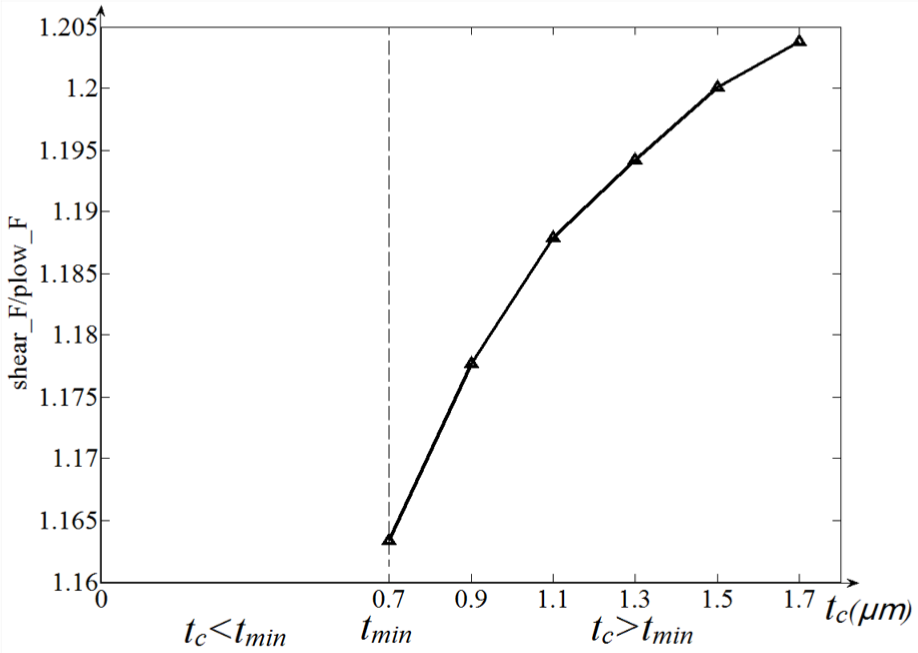
The changes in ratios of shear force to ploughing force with the cutting thickness.
Conclusion
Based on the instantaneous undeformed chip thickness model and the micro-milling force analytical model including shear-dominant and ploughing-dominant models, a new micro-milling force model is presented in this article. There are basically two main improvements as the following:
For the cutting force prediction model during shear-dominant cutting process, the force is divided into two parts: one is the shear force to create chips and the other is the ploughing force caused by the arc radius of cutting edge, of which the effects are commonly ignored in traditional macro-scale milling. Cutting forces during shear-dominant cutting process are obtained by adding these two parts.
Based on Fourier’s law, the micro-milling cutting area is simplified as a moving heat source with finite length, and an analytical temperature model is established.
The coupled thermal–mechanical analyses are conducted, and the micro-milling force prediction model with the consideration of cutting temperature is obtained.
The influences of cutting parameters on micro-milling force and temperature are discussed based on the experimental results. Within the range of the selected cutting parameters, the spindle speed has little influence on micro-milling force, but the cutting temperature increases significantly with the increase in spindle speed. The micro-milling force and temperature tends to increase at first but then decrease with the increase in feed per tooth, and the turning point is at the minimum cutting thickness. The micro-milling force and temperature increase with the increase in cutting depth.
The novelty of this article is including cutting temperature into micro-milling force model, which simulates the interaction between cutting force and cutting temperature during micro-milling. The established model explores the micro-milling mechanism and lays a foundation for subsequent work hardening research.
Footnotes
Declaration of conflicting interests
The author(s) declared no potential conflicts of interest with respect to the research, authorship, and/or publication of this article.
Funding
The author(s) disclosed receipt of the following financial support for the research, authorship, and/or publication of this article: The research is supported by the National Natural Science Foundation of China under Grant No. 51305061, the Fundamental Research Fund for the Central Universities under Grant No. DUT17JC22, and the State Foundation for Studying Abroad (CSC) under Grant No. 201606065043. The financial contributions are gratefully acknowledged.