
Abstract
A two-stage series-parallel vibration isolation system is already widely used in various industrial fields. However, when the researchers analyze the vibration characteristics of a mechanical system, the system is usually regarded as a single-stage one composed of two substructures. The dynamic modeling of a two-stage series-parallel vibration isolation system using frequency response function–based substructuring method has not been studied. Therefore, this article presents the source-path-receiver model and the substructure property identification model of such a system. These two models make up the transfer path model of the system. And the model is programmed by MATLAB. To verify the proposed transfer path model, a finite element model simulating a vehicle system, which is a typical two-stage series-parallel vibration isolation system, is developed. The substructure frequency response functions and system level frequency response functions can be obtained by MSC Patran/Nastran and LMS Virtual.lab based on the finite element model. Next, the system level frequency response functions are substituted into the transfer path model to predict the substructural frequency response functions and the system response of the coupled structure can then be further calculated. By comparing the predicted results and exact value, the model proves to be correct. Finally, the random noise is introduced into several relevant system level frequency response functions for error sensitivity analysis. The system level frequency response functions that are most sensitive to the random error are found. Since a two-stage series-parallel system has not been well studied, the proposed transfer path model improves the dynamic theory of the multi-stage vibration isolation system. Moreover, the validation process of the model here actually provides an example for acoustic and vibration transfer path analysis based on the proposed model. And it is worth noting that the proposed model can be widely applicable in mechanical systems.
Keywords
Introduction
Nowadays, with the development of the modern industry, when all kinds of production machinery and transportation machinery are toward high speed and high efficiency, more and more emphasis is laid on the noise and vibration control of them at the same time. A large amount of effort has been invested into the improvement of the technology of noise and vibration reduction and containment. 1
A two-stage vibration isolation system composed of three substructures is now widely used in various industrial fields. There are two kinds of two-stage isolation systems. One is defined as a two-stage series vibration isolation system (shown in Figure 1) and the other one is defined as a two-stage series-parallel vibration isolation system (shown in Figure 2). In a two-stage series system, substructure C as the vibration source is mounted on the substructure B and through it connected to substructure A (receiver). In a two-stage series-parallel system, substructure C is connected to both substructures A and B. And this article will focus on the series-parallel vibration isolation system.

Two-stage series isolation system.

Two-stage series-parallel isolation system.
Actually, at present, when the researchers analyze the vibration transfer characteristics of a system, the lumped mass method is usually applied. However, in a lumped mass model, the stiffness of the springs is a definite value, which is greatly different from an actual complex structure. Therefore, in this article, the dynamic modeling of a two-stage series-parallel vibration isolation system is finished using frequency response function (FRF)-based substructuring method. The FRF-based substructuring method has already been studied by some researchers.
In the end of 1980s, the FRF-based substructure synthesis method began to be studied. Jetmundsen et al. 2 set up the equations for classic substructure method. Van der Valk 3 summed up the current difficulties of substructure method in testing part. And based on a benchmark model, a further study of the difficulties was made. Through an analytical model, Nicgorski and Avitabile 4 discussed the problems with the system response prediction in implementation with actual test data. The numerical simulation results showed that the low-frequency information of a system is very sensitive to noise on the data. Nicgorski and Avitabile 5 developed a method of conditioning test data for use with frequency based substurcturing (FBS). The method is referred to as variability improvement of key inaccurate node groups (VIKING). Through experiments, the method was proved to be effective. Lee and Hwang 6 suggested a designed sensitivity formulation using a multi-domain FRF-based substructuring method for complex systems. The designed sensitivity formulation is applied to an engine mount system of a passenger car. Zhen 7 and Lei 8 developed a spectral-based substructuring technique and a FRF-based inverse substructuring theory for analyzing vehicle system NVH (noise, vibration, and harshness) response. A Ford car was regarded as a two-substructure vehicle system and the inverse substructuring technique was applied to analyze its vibration properties. Wang and Chuang 9 proposed a new method to identify the structural joint parameters directly from the FRFs of the substructures and the whole structure. P Sjövall and T Abrahamsson 10 identified the substructure systems from coupled system test data. The method was based on reconstruction of the interface forces acting between the unknown subsystem and its neighbor. Pradhan and Modak 11 posed the issue of identification of damping matrix of a structure as a finite element (FE) damping matrix updating problem. They developed an updating formulation that seek to separate updating of the damping matrix from that of updating of the stiffness and the mass matrix and found that the proposed method was effective in the accurate identification of the damping matrix in cases of complete, incomplete, and noisy data and was not limited by the level of damping in the structure. Mayes et al. 12 presented two new metrics that could be used to determine the cause of indefinite mass or stiffness matrices after substructure uncoupling. ZW Wang et al. 13 applied the inverse substructuring method in the investigation on dynamic characteristics of a product transport system. ZW Wang and J Wang 14 applied the inverse substructuring approach in a three-substructure system dynamic analysis. Law and Yong 15 presented two substructural identification methods with the structure divided into substructures and with one substructure assessed at one time. The two methods can be used to identify external excitations iteratively in a substructure with time domain information. Both methods were validated with a truss structure. Čelič and Boltežar 16 presented a method for establishing a theoretical model of a joint from the substructures and assembly FRF data. Voormeeren and Rixen 17 found that the decoupling (or identification) of a substructure from an assembled system arisen when substructures could not be measured separately but only when coupled to neighboring substructures. W D’Ambrogio and A Fregolent18,19 investigated the inverse dynamic substructuring problem, or decoupling problem. The direct decoupling techniques based on a hybrid assembly approach were emphatically considered. And a well-known issue in experimental dynamic substructuring relating to rotational degrees of freedom (DOFs) was settled. It was verified that rotational DOFs are not essential in the decoupling problem. SN Voormeeren et al. 20 derived an uncertainty propagation method to investigate the problem of small random errors on substructure measurements in experimental dynamic substructuring using FRFs.
According to the present literatures, when inverse substructuring method is applied to analyze the system vibration, the system is usually regarded as a single-stage vibration isolation system instead of a two-stage one. Although the inverse substructuring method for coupled two-stage product-transport-system has already been studied, but the method is only suitable for the single coordinate coupling system. Moreover, researchers have only validated the method based on a simple lumped mass model. In fact, there are great differences between the model and the actual structure. And the dynamic modeling of a two-stage series-parallel vibration isolation system has not been studied. However, this structure is already widely used in different kinds of mechanical system. Hence, it is necessary to make a research on it in this article.
Here, the source-path-receiver model and substructure property identification model of a two-stage series-parallel isolation system are developed using FRF-based substructuring method. And the model is programmed by MATLAB. To verify these two models, a finite element model (FEM) simulating a vehicle system, which is a typical two-stage series-parallel vibration isolation system, is designed. The structural FRFs and system level FRFs can be obtained by MSC Patran/Nastran and LMS Virtual.lab based on the FEM. The FRFs of substructures and the joint stiffness can be predicted by the system level FRFs through the substructure property identification model; the system response of coupled structure can be predicted by the calculated FRFs of substructures and joint stiffness through the source-path-receiver model. By comparing the predicted results and exact values, these two models will be validated. Furthermore, the random noise is introduced into the relevant system level FRFs for error sensitivity analysis and then its influence on the substructure FRFs is quantified by comparison.
Modeling of coupled series-parallel two-stage isolation system
According to the FRF-based substructuring method, a system can be divided into several independent substructures, which are coupled by springs and damping elements. Each substructure can be represented by its FRF matrix corresponding to specific coordinates. 8 A two-stage series-parallel system is partitioned into three substructures as shown in Figure 2. The coupling mounts between the three substructures are modeled as scalar springs.
Source-path-receiver model
A substructure M is shown in Figure 3. The relationship between the excitation and the response can be represented by a transfer function matrix

where

General substructure representation.
Accordingly, equation (1) can be expanded as follows

As shown in Figure 4, the two-stage series-parallel isolation system S is composed of substructures A, B, and C. Substructures A and B are connected via a set of flexible springs


A two-stage series-parallel isolation system.
It can be seen from Figure 4 that excitation at excitation coordinate of subsystem

According to equation (4), the system response

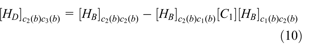
Since the structure D consists of substructures A and B, the FRFs of structure D can be expressed by the FRFs of substructures A and B using the same derivation method described in Appendix 2
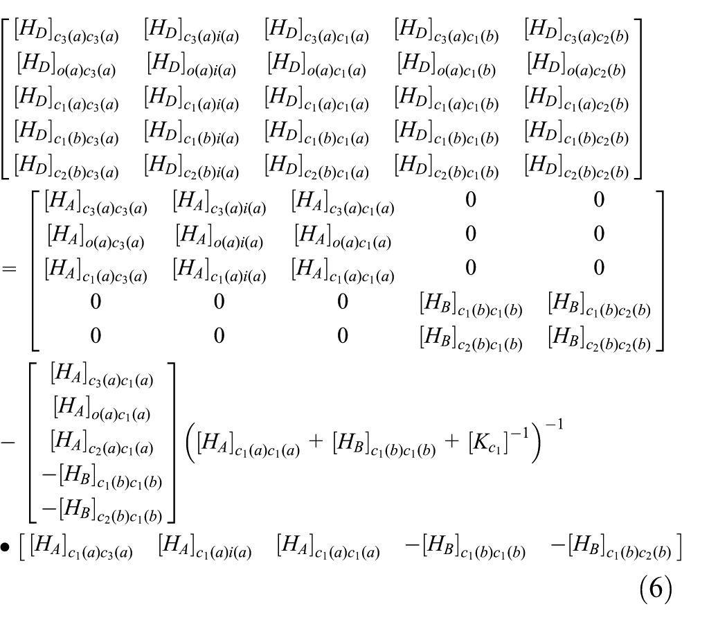

In accordance with the equations (6) and (7), the FRFs of the structure D can be expressed as follows


From the above derivation, the source-path-receiver model of a two-stage series-parallel vibration isolation system is developed. The system level FRFs of coupled structure can be predicted by the calculated FRFs of substructures and coupling stiffness in free state through the source-path-receiver model.
Substructure property identification model
In order to obtain the FRFs of substructures in free state, the coupled structure needs to be decoupled, which usually costs quite a lot of time. Therefore, it is better to identify substructure property in the coupling condition. In this section, the FRFs of substructures and coupling stiffness in free state of the two-stage series-parallel vibration isolation system will be predicted through the coupled system level FRFs.
,
, and substructure A
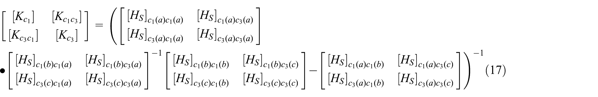
To calculate the FRFs of the substructure A in free state, the coupling stiffness

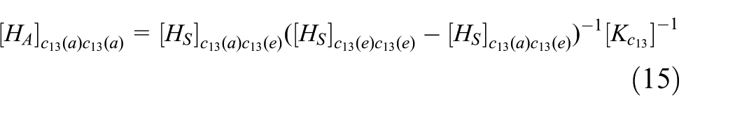
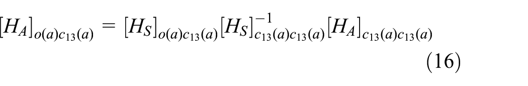
Since the coordinate


and substructure B
To calculate the FRFs of the substructure B, coupling stiffness


Substructure C
To calculate the FRFs of the substructure C, the substructures A and B are treated as a new substructure G. Using the derivation method mentioned in Appendix 3, equations (22)–(24) can be obtained

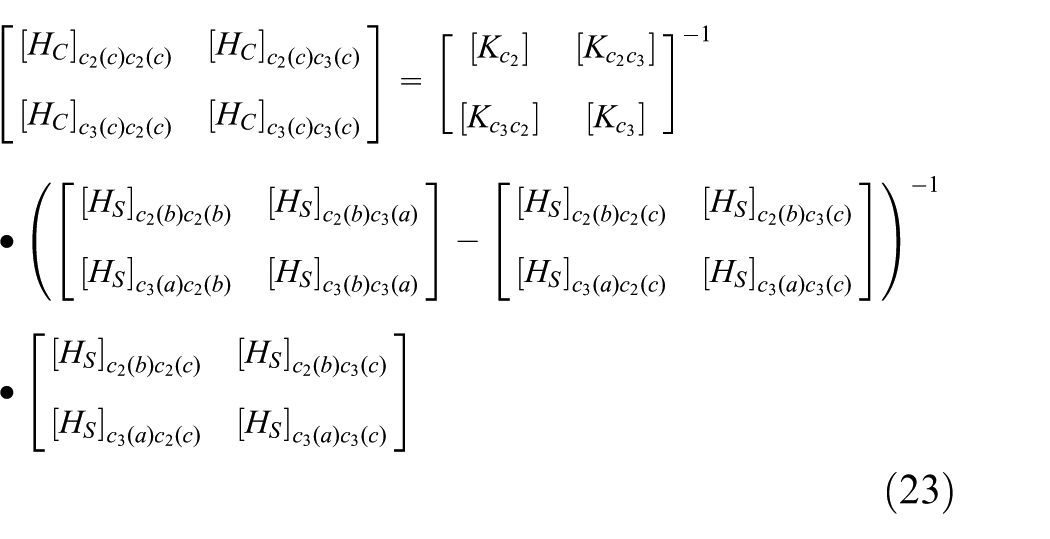

Up to this point, the substructure property identification model of the two-stage series-parallel system is developed (equations (17)–(24)). The FRFs of substructure and coupling stiffness in free state can be predicted by the system level FRFs of the coupled structure.
To sum up, the source-path-receiver model and the substructure property identification model make up the transfer path model of a two-stage series-parallel vibration isolation system. The transfer path model relates the substructure level dynamic characteristics to the overall system dynamic responses. The source-path-receiver model shows the relationship between the system level FRFs and the substructure level FRFs in free state. And through the substructure property identification model, the FRFs of substructures and coupling stiffness in free state can be calculated by system level FRFs of coupled structure.
FEM-based validation
In previous section, the transfer path model of a two-stage series-parallel isolation system is developed. In this section, a FEM is designed to validate the transfer path model.
Validation process
The transfer path model of a two-stage series-parallel isolation system model can be validated by the following steps. As shown in Figure 5, first, a simplified model of a two-stage series-parallel isolation system is built by CATIA and then the FE model of both the substructures and coupled system can be generated in Hypermesh. The FRFs of each substructure in free state and system level FRFs of coupled structure can be obtained by MSC Patran/Nastran and LMS Virtual.lab based on the FEM. Then, the system level FRFs are substituted into the substructure property identification model to predict the substructure FRFs matrix and coupling stiffness using MATLAB program. By comparing the predicted substructure FRFs and the exact values, the substructure property identification model is verified. Then, we substitute the calculated FRFs of substructures and coupling stiffness into the source-path-receiver model to predict the system response of coupled structure using MATLAB program. By comparing the predicted system response and the direct response calculations, the source-path-receiver model is verified.

The process of validation based on FEM.
Frequency response analysis based on FEM
Finite element model
As mentioned above, the two-stage series-parallel vibration isolation system is a common structure in various mechanical systems and a vehicle system is one of them. Here, we will take it as an example to build the FEM to carry out the validation. As shown in Figure 6, a three-dimensional (3D) model of the system is set up. Substructure A represents the vehicle body. Substructure B is regarded as the subframe. The substructure C simulates the powertrain. Substructures A and B are connected via four bushings simulating the subframe mounts; substructures B and C are connected via a bushing simulating the powertrain mount; substructures A and C are connected via two bushings simulating the powertrain mounts.

The two-stage series-parallel system model simulating a vehicle system.
Then, the entity models of substructures A, B, and C from CATIA are imported into Hypermesh to generate the FE models. The FEM of the coupled system can be got by assembling FE models of three substructures through seven bushings as shown in Figure 7.

FEM of coupled system.
In the FE model, each bushing is represented as a set of three orthogonal scalar springs and damping elements. They locate at the coupling coordinates between the substructures. The dynamic stiffness of the springs and damping elements can be obtained from the test: (a) axial stiffness, 709 N/mm; axial damping, 0.48 N s/mm and (b) radial stiffness, 7650 N/mm; radial damping, 3.8 N s/mm.
FRF analysis
The structural and acoustic FRFs can be obtained by MSC Patran/Nastran and LMS Virtual.lab. The FRFs of substructures A, B, and C and coupled system S are shown in Table 1. The system target response includes the vibration acceleration in X-, Y-, and Z-direction at coordinate o(a) and the sound pressure at coordinate os(a). It can be seen from Figure 8 that the excitation points of the coupled system include point A1, A2, A3, A4, A5, A6, B1, B2, B3, B4, B7, C5, C6, C7, i(c) and the response points include the vibration acceleration point o(a), A1, A2, A3, A4, A5, A6, B1, B2, B3, B4, B7, C5, C6, C7, i(c) and the sound pressure point os(a); the excitation points of substructure A include A1, A2, A3, A4, A5, A6 and the response points include the vibration acceleration point o(a), A1, A2, A3, A4, A5, A6 and the sound pressure point os(a); Figure 9(b) shows that the excitation points of substructure B include point B1, B2, B3, B4, B7 and the response points also include B1, B2, B3, B4, B7; Figure 9(c) shows that both the excitation points and the response points of substructure C incorporates C5, C6, C7, i(c). When analyzing the frequency response of the system and the substructures, the excitation in X-, Y- and Z-direction will be exerted on every excitation point. Then, response of the vibration acceleration points and the sound pressure points can be obtained.
The list of FRFs.

FRFs: frequency response functions.

The FRFs of the coupled structure.

The FRFs of substructures: (a) substructure A, (b) substructure B, and (c) substructure C.
Comparison of predicted results and exact values
Validation of the substructure property identification model
In previous sections, the FEM is already developed and the frequency response analysis is finished. Based on the validation process mentioned above, the validation of the substructure property identification model of the two-stage series-parallel isolation system is carried out here. The predictions of following FRFs are verified.
Free substructure FRFs of substructure A:
Free substructure FRFs of substructure B:
Free substructure FRFs of substructure C:
Coupling stiffness:
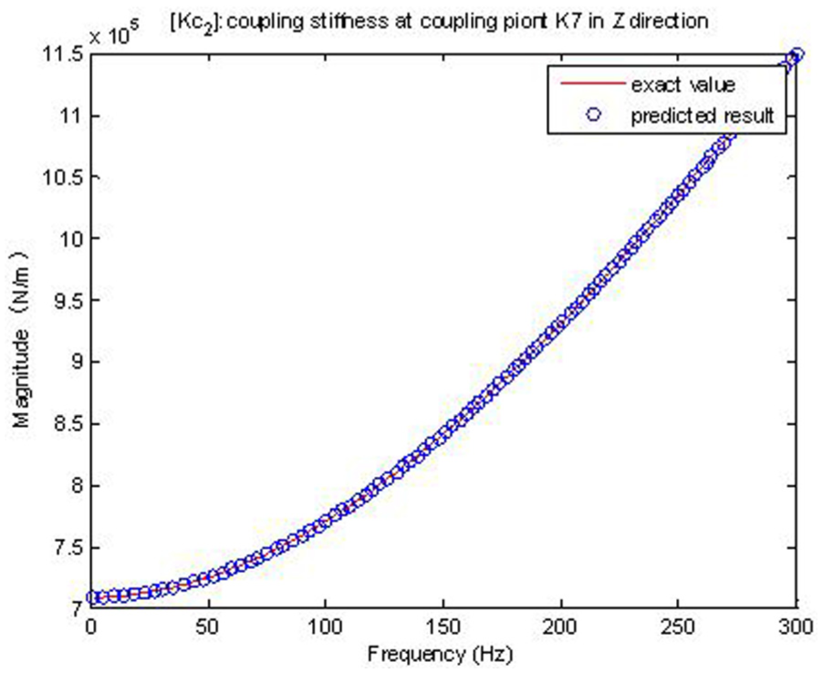
Due to the length limitation, only a part of the figures are shown here. Figures 10–15 show the comparison between the calculated substructure level FRFs and the exact values. It can be seen that the predicted results match very well with the direct frequency response. Thereby, we can draw the conclusion that the FRFs of substructures and coupling stiffness in free state can be predicted by the system level FRFs of the coupled structure through the substructure property identification model of the two-stage series-parallel isolation system.


Validation of the source-path-receiver model
As mentioned in the section “Validation process,” the calculated FRFs of substructures and coupling stiffness from previous section are substituted into the source-path-receiver model to predict the system response


Up to this point, the transfer path model of the two-stage series-parallel isolation system is already verified. It is worth noting that the proposed transfer path model is suitable for any linear mechanical systems, which can be simplified as a two-stage series-parallel structure although the validation is finished based on a FEM simulating the vehicle system.
Application
The verified transfer path model is of practical utility. It can be applied at several steps of a product development, such as trouble-shooting process and pre-prototype design.
According to the transfer path model, the system response can be first cascaded to the FRFs of substructures C, D and coupling stiffness between substructures D and C. The FRFs of substructure D can be further partitioned into the FRFs of substructures A, B and coupling stiffness between substructures A and B in free state (shown in Figure 18).

Cascading relationship of the system response.
It is obvious that with the application of the transfer path model, every possible transfer path that contributes to the system response can be identified. The transfer path model can ease the trouble-shooting process of a product development. As mentioned above, the system response can be cascaded to the substructure level. Therefore, based on the model the problem area, namely the most effective location for palliative treatment, can be easily addressed.
The cascading of the system response based on the transfer path model also helps in a pre-prototype design. The designer can substitute different components into the various paths and use a sound quality replay system to listen to the effects subjectively during the early design stages. 21
In general, the transfer path model of a series-parallel two-stage isolation system is a powerful tool for the trouble-shooting process and pre-prototype design of a product development.
Error sensitivity analysis
In a FEM-based simulation, noise is not considered. However, random noise is unavoidable in the actual measurement of FRFs. Random noise may reduce the accuracy of the predicted FRFs. Regardless of how precise the FRFs are measured, the estimated FRFs will not correspond perfectly to the true transfer function between the input and output. 8 Hence, in this section, the random noise is introduced into the relevant system level FRFs for error sensitivity analysis and then its influence on the substructure FRFs is quantified by comparison. Additional care should be taken, when acquiring the system level FRFs which are most sensitive to the random errors.
Inputs and outputs of error sensitivity analysis
Before the error sensitivity analysis, the inputs and outputs are confirmed. As shown in Figure 19, based on the transfer path model, the FRFs of substructures and coupling stiffness, which are used to predict the system response

The inputs and outputs of the error sensitive analysis.
The substructure level FRFs mentioned above are considered as the outputs of the analysis. The 16 independent outputs are as follows:
Sensitivity analysis of different input FRFs
As we can see from Figure 19, each output is affected by several inputs. The error sensitivity analysis aims to find out the system level FRFs which are most sensitive to random noise and it may have the greatest influence on the outputs. For the analysis, some levels of random errors are introduced into the input FRFs (direct frequency response) individually. Here, we take 5% random error as an example. The exact system level FRFs with random errors are substituted into the substructure property identification model (equations (17)–(24)) to calculate the substructure FRFs. The system response can be predicted by calculated substructure level FRFs through the source-path-receiver model. The prediction error of the outputs is shown in Figures 20–26 and represented in the form of relative Frobenius norm error defined as follows

where


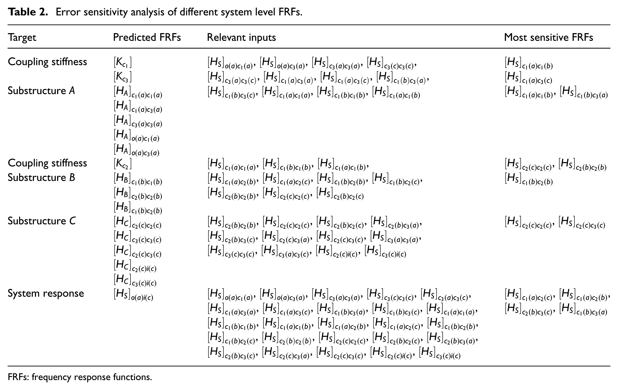
Due to the length limitation, only a part of the figures are shown here. Table 2 summarizes the results of the error sensitivity analysis.
Figures 20, 21, and 23 show the effect of 5% input error on the prediction error of
Figure 22 shows the effect of 5% input error on the prediction error of substructure A. Random errors are added to relevant system level FRFs (as shown in Table 2) individually. It is obvious that additional care should be taken, when acquiring the system level FRFs
Figure 24 shows the effect of 5% input error on the prediction error of substructure B. Random errors are added to relevant system level FRFs (as shown in Table 2) individually. Obviously, the prediction error of substructure B is mainly determined by system level FRF
Figure 25 shows the effect of 5% input error on the prediction error of substructure C. Random errors are added to relevant system level FRFs (as shown in Table 2) individually. It can be seen that the prediction error is more sensitive to the random error added to
Figure 26 shows the effect of 5% input error on the prediction error of system response
Error sensitivity analysis of different system level FRFs.
FRFs: frequency response functions.
Conclusion
A single-stage vibration isolation system model is already well developed by some researchers. However, a two-stage series-parallel isolation system has not been studied although it is already a widely used structure in mechanical field. Hence, in this article, the source-path-receiver model and the substructure property identification model of a two-stage series-parallel vibration isolation system are developed using FRF-based substructuring method. These two models make up the transfer path model of the system. And the model is programmed by MATLAB. Next, the transfer path model is validated through a FE model simulating a vehicle system. The FRFs of substructures in free state and system level FRFs of coupled structure are obtained by MSC Patran/Nastran and LMS Virtual.lab based on the FEM. Then, the FRFs of substructures and the joint stiffness are predicted by the system level FRFs through the substructure property identification model; the system response of coupled structure is predicted by the calculated FRFs of substructures and joint stiffness through the source-path-receiver model. The results of the simulation reveal that the predicted system response and substructural FRFs match very well with the exact values. Therefore, the proposed transfer path model is verified. Furthermore, considering that noise is unavoidable in the actual measurement, random noise is introduced into relevant system level FRFs for error sensitivity analysis. The analysis results show that the transfer path model is very sensitive to the random noise and the system level FRFs, which are most sensitive to the random errors, are found. Additional care should be taken, when acquiring these FRFs.
In general, the transfer path model proposed here further develops the dynamic theory of the multi-stage vibration isolation system. Such a widely used two-stage series-parallel system has not been deeply studied previously. Moreover, based on the model, a detailed acoustic and vibration transfer path analysis process is also presented here. Above all, the model can be applied in any mechanical systems.
Footnotes
Appendix 1
Appendix 2
Appendix 3
Academic Editor: Tian Han
Declaration of conflicting interests
The author(s) declared no potential conflicts of interest with respect to the research, authorship, and/or publication of this article.
Funding
The author(s) disclosed receipt of the following financial support for the research, authorship, and/or publication of this article: This work was supported by the National Natural Science Foundation of China (grant number 51205290) and the Fundamental Research Funds for the Central Universities (grant number 1700219118).