
Abstract
In machine tools, the trajectory error of the tool center point (TCP) is caused due to the dynamic positioning error of feed drive systems according to the relationship in spatial structure and motion. The dynamic positioning error of the feed drive system includes axial dynamic error and lateral dynamic error. To analyze the influence of the lateral dynamic error on the trajectory error of the TCP of multi-axis machine tools, in this study, circular and butterfly trajectories were designed as the set trajectories of a machine tool with three linear axes. In addition, the tracking error models were constructed both considering the lateral dynamic error and without considering the lateral dynamic error, and the difference between the two models was quantified. The Sobol method was then used to analyze the sensitivity of the lateral dynamic error of the feed drive system to the tracking error of the TCP. Finally, experiments were performed on a three-axis machine tool. The results show the maximum lateral dynamic error in the direction perpendicular to the motion direction is 0.026 mm. The lateral dynamic error detrimentally affects the tracking error and contour error of the TCP in multi-axis machine tools.
Keywords
Introduction
Computerized numerical control (CNC) machine tools constitute the foundation of the manufacturing industry, and the quality of the workpiece heavily depends on the machining accuracy of the machine tool. Contour error greatly affects the machining accuracy of the machine tool, and tracking error is the primary cause of contour error. 1 Therefore, understanding the mechanism and characteristics of trajectory errors is crucial for improving the machining quality in terms of structure, control, and compensation and is the focus of the current study.
Tracking error is closely related to the mechanical structure, control system, operating status, load change, and internal and external disturbance.2,3 Numerous error compensation and error reduction techniques, 4 related to structural optimization, parameter matching, control methods trajectory optimization, and inertia matching have been developed. According to the object of study, tracking error can be divided into two categories: tracking error of the feed drive system and tracking error of the tool center point (TCP) of the machine tool.
For the feed drive system, tracking error is defined as the deviation between the reference input and the actual output. 1 To minimize the tracking error by optimizing the structure of the feed drive system, dynamic modeling methods have been developed, and characteristic analyses have been performed. The lumped parameter method is the most commonly used modeling method.5,6 However, the accuracy of this method is limited, so the hybrid modeling method is adopted to improve the model accuracy. 7 The time-varying dynamic characteristic is an important factor for tracking error control 8 and is derived from the changes in the moving components’ position, loading, 9 temperature, friction, 10 acceleration, 11 and disturbance. Various control strategies have been employed to reduce tracking errors. Dong et al. 12 designed an again-scheduled H∞ loop shaping controller to achieve high tracking performance against dynamic variations. Shirvani et al. 13 addressed the problem of harmonic positioning error reduction in the feed drive system by employing adaptive feedforward cancellation. Dumanli and Sencer 14 proposed an optimal non-collocated pole placement control strategy for wide-bandwidth control of the feed drive system suffers from lightly damped structural resonance. Furthermore, the tracking error can be reduced using the effectual compensation method. In order to compensate for the elastic deformations, Li et al. 15 and Kamalzadeh et al. 16 adopted a closed-loop scheme with a dynamic model to offset the position commands. Lee et al. 17 proposed a friction observer based on a Kalman filter with load estimation for friction compensation control considering the changes in the applied load. Zhang et al. 18 presented a compensation strategy based on the mounting condition by using a prediction model for the positioning error of the feed drive system. Yang et al. 19 presented a review on vibration analysis and control of machine tool feed drive systems. Lyu et al. 20 systematically summarized the dynamic error of CNC machine tools. However, the aforementioned studies focus only on the axial errors and ignore the lateral errors of the feed drive system. Moreover, most of the studies on tracking errors have been performed on encoders in a closed loop. Dynamic error can be divided into dynamic error inside the servo loop and dynamic error outside the servo loop. 20 The influence of dynamic error outside the servo loop on the trajectory error has been studied by Lyu et al., 21 but they did not investigate the lateral dynamic error. For a feed drive system undergoing force and disturbance, both axial and lateral dynamic errors exist. ISO 230-1 22 presents the lateral geometric errors of axes of linear motion operating under no-load or quasi-static conditions, and ISO 230-8 23 shows the lateral dynamic errors from environmental vibration tested in the machine under static conditions. However, the lateral dynamic error is time-varying, closely related to the system vibration, and affected by the dynamic characteristics of the mechanical structure, internal and external disturbances of the system, and load. 24 The influence of the lateral dynamic error on the trajectory error can be ignored when the accuracy requirement is not high. However, for realizing a high-precision feed drive system, the lateral dynamic error cannot be ignored because it deteriorates the positioning precision. Thus, the lateral dynamic error must be studied to improve the movement precision of the feed drive system.
For the multi-axis motion system, the tracking error is defined as the deviation between the ideal position and the actual position of the TCP. 1 The tracking error of the TCP is caused by the positioning error of the feed drive system according to the relationship between spatial structure and motion. Contour error is defined as the orthotropic distance between the actual position point and the desired trajectory. 1 The reduction of tracking error and contour error for multi-axis machine tools is mainly developed from two aspects: control and compensation. Msukwa et al. 25 used an adaptive nonlinear sliding mode controller with a feedforward compensator and a model predictive control to improve the tracking performance of a biaxial feed drive system, respectively. Yang et al. 26 reduced the contour error by error compensation method for free-form two-dimensional. For the three-axis machine tools, Corapsiz and Erenturk, 27 proposed a control approach for improving the trajectory tracking ability and contouring performance. Liu et al., 28 Hu et al., 29 and Wang et al. 30 based on the error-sated strategy to improve the tracking performance, respectively. Compared with the three-axis machine tool, the five-axis machine tool can be set up to form the free-form trajectory considering the position and pose of the tool simultaneously. Hu et al. 31 proposed an online and high-accuracy contour error estimation algorithm for five-axis CNC machining. The contour errors are effectively suppressed by online compensation that the estimated contour error components of each axis are compensated to the position-loop controller of each axis to realize contour error control. Xiang and Altintas 32 proposed a method to measure, model, and compensate for both geometrically dependent and independent volumetric error of the five-axis. Zhong et al. 33 proposed a new method to identify the lateral error of machine tools and gave an optimal method to improve the volumetric compensation accuracy. Whereas, the component errors of the feed drive system were measured under quasi-static conditions in both Xiang and Altintas 32 and Zhong et al. 33 It can be seen from the above literature the tracking error models employed in these studies do not include the influence of the lateral dynamic error of the feed drive system, and the research on volumetric error measured geometric error under quasi-static conditions. However, for high precision, the lateral dynamic error must be considered and not allowed in the studies of tracking error, because it causes overcut and undercut, tool vibration, tool failure, vibration marks, and vibration noise. Moreover, in the case of high speeds, high accelerations, and heavy loads, the dynamic error is the primary reason for tracking error and contour error 20 ; thus, the lateral dynamic error becomes an important factor in the study of tracking error and contour error under such conditions. Andolfatto et al. 24 quantified the relative impact of the dynamic error nearly 5% of the total error, considering the mean value of the norm. However, the lateral dynamic error is not included. The lateral dynamic error, different from the lateral geometric error, is measured under dynamic conditions and has obvious vibration characteristics. It is of great significance to reveal the influence of lateral dynamic error on the tracking error of TCP for the research of tracking error suppression and compensation in machine tools.
In this study, the influence of lateral dynamic error on the trajectory error is analyzed on a three-axis motion system. This paper is arranged as follows. First, the lateral dynamic error is defined and discussed in Section “Definition of the Lateral dynamic error.” In Section “Analysis of the influence of lateral dynamic error on the trajectory error of three-axis machine tools,” the tracking error models both with and without the lateral dynamic error are established, and the sensitivity analysis of the lateral dynamic error on the tracking error of the TCP is performed using the Sobol method. The influence of the lateral dynamic error of the feed drive system on the tracking error and contour error of the three-axis motion system is experimentally verified in Section “Experimental verification.” Finally, the conclusions are drawn in Section “Conclusions.”
Definition of the lateral dynamic error
The Feed drive system is mainly composed of a motor, transmission components, moving components, and guide sliders. An equivalent model is illustrated in Figure 1; LT is the reference input position of the feed drive system, whereas LL, LAL, and LAE are the actual output positions. The dynamic positioning errors represented by the distance between LT and LAE consist of three components: xx, xy, and xz in the x-direction, y-direction, and z-direction, respectively. xx is the axial dynamic error, whereas xy and xz are the lateral dynamic errors. Lateral dynamic error, defined as the time-varying dynamic deviation perpendicular to the motion direction, is related to the structural characteristics of the feed drive system. Furthermore, the lateral dynamic error is mainly affected by structural flexibility, elastic vibration, rigid body motion, and external disturbance.
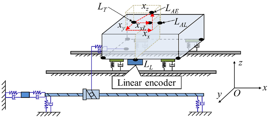
The dynamic positioning error of the feed drive system.
LL is the actual position determined by the linear encoder, and LAL is the actual position of the point on the moving component moving along a nominal trajectory. The difference between LL and LAL is the dynamic error outside the servo loop, which has been studied in detail by Lyu et al. 20 LAE is the actual position determined by the laser tracker. The difference between LAE, LAL, and LL is discussed in the current study, and the influence of the lateral dynamic error on the trajectory error is discussed in the following sections.
Analysis of the influence of lateral dynamic error on the trajectory error of three-axis machine tools
Tracking error model derivation both with and without lateral dynamic error
Most machine tools employ a series structure, and the movement of the TCP relative to the workpiece point is achieved through each feed drive system based on the spatial structure relationship. The dynamic positioning error of each feed drive system leads to the tracking error and contour error of the TCP, which deteriorates the accuracy of multi-axis machine tools. A three-axis machine tool is shown in Figure 2(a). There are three linear motion axis in the x-direction, y-direction, and z-direction, respectively.
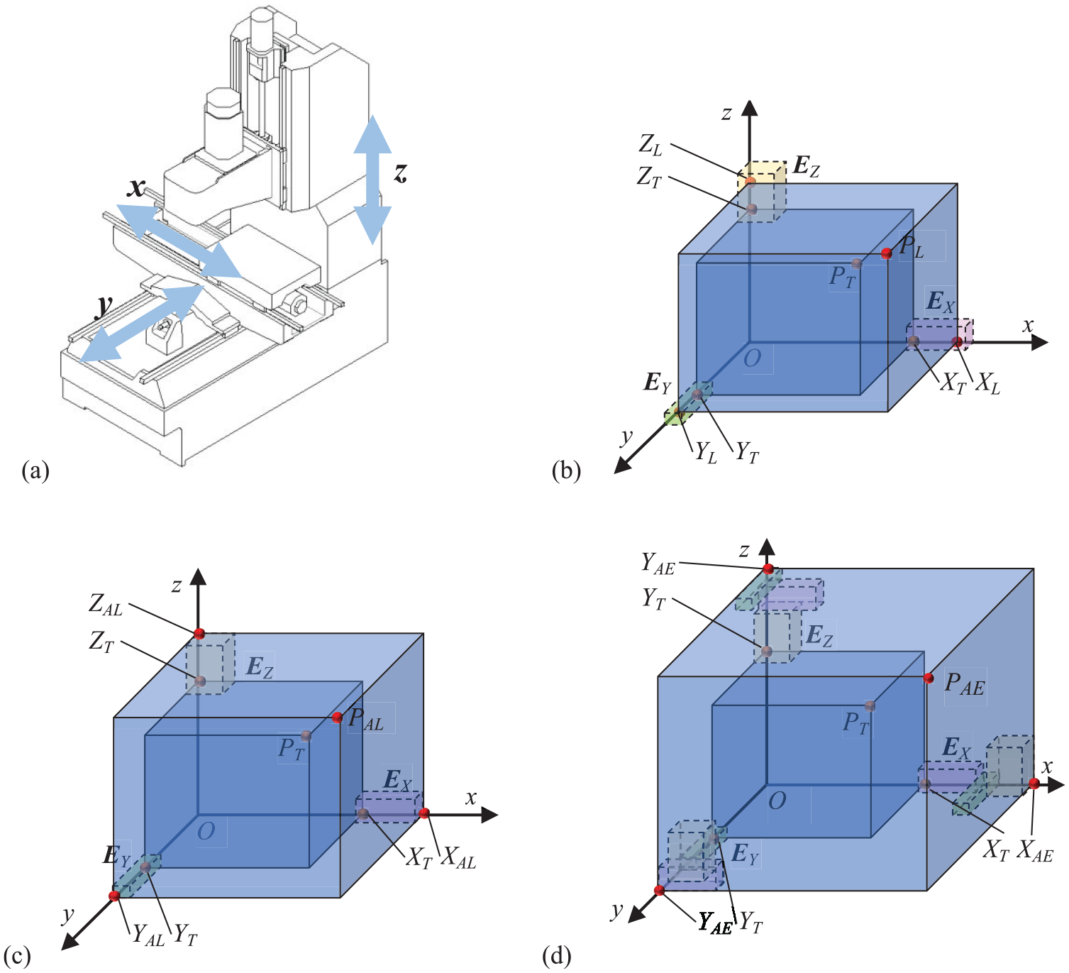
Tracking error model of a three-axis motion system: (a) three-axis machine tool, (b) linear encoder feedback position, (c) the effector end position without lateral dynamic error, and (d) the effector end position with lateral dynamic error.
Figure 2 shows the mechanism of the tracking error of the three-axis motion system. PT (XT, YT, ZT) is the reference position of the TCP. PL (XL, YL, ZL) is the actual position of the TCP determined by the linear encoder. PAL (XAL, YAL, ZAL) is the actual position of the TCP when considering the dynamic error outside the servo-loop. PAE (XAE, YAE, ZAE) is the actual position of the TCP determined by the laser tracker when considering the lateral dynamic errors.
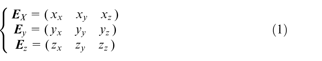
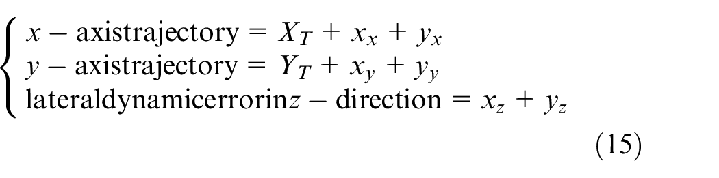
where xx, xy, and xz are the deviations of the x-axis in the x-direction, y-direction, and z-direction, respectively. yx, yy, and yz represent the deviations of the y-axis in the x-direction, y-direction, and z-direction, respectively. zx, zy, and zz denote the deviations of the z-axis in the x-direction, y-direction, and z-direction, respectively.
According to Lyu et al., 20 xx includes the dynamic error inside the servo loop and dynamic error outside the servo loop, which can be written as follow:

where xxI is the dynamic errors inside the servo loop of the feed drive system in the direction of motion, and xxO is the dynamic errors outside the servo loop of the feed drive system in the direction of motion.
As shown in Figure 2(b) to (d), PT, PL, PAL, and PAE can be calculated based on multi-body kinematics theory:
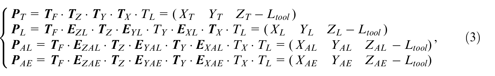
where
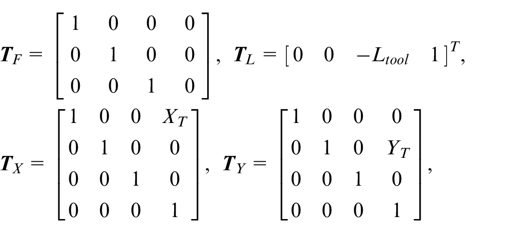
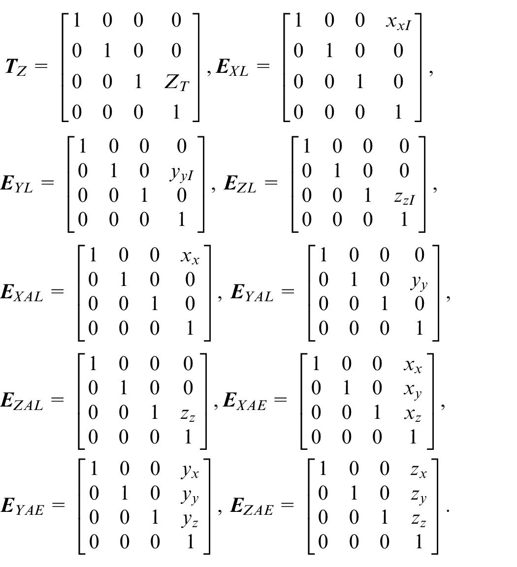
Meanwhile, XL, YL, ZL, XAL, YAL, ZAL, XAE, YAE, and ZAE can be expressed as:
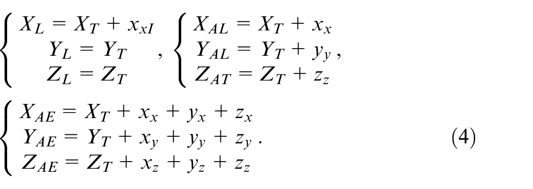
E L T is defined as the tracking error from PL to PT and considers only the influence of the dynamic error inside the servo loop:

E AL T is defined as the tracking error from PAL to PT and does not consider the influence of the lateral dynamic error on the trajectory error:

The deviation EAL L between PAL and PL can be calculated as follows:

It can be seen a difference of the end position with or without considering outside servo loop dynamic error. EAL L depends on the xxO, yy, and zz, which are not included in the linear encoder closed loop.
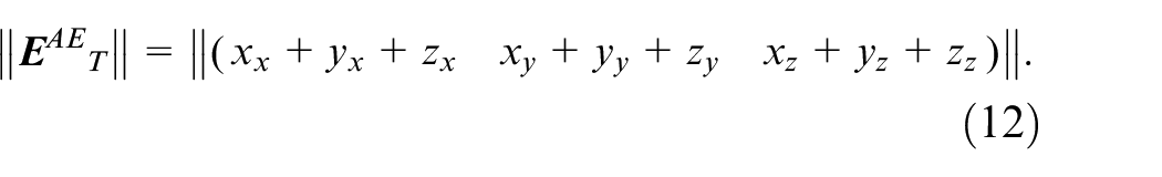
E AE T is defined as the tracking error from PAE to PT and considers the influence of lateral dynamic error on trajectory error:
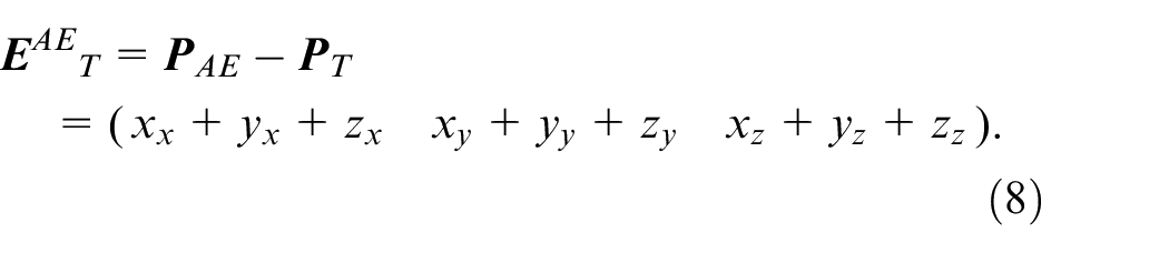
The deviation EAE L between PAE and PL can be described as:
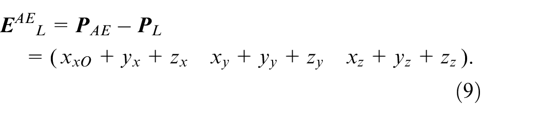
By equation (9), it can be seen that the error model considering the lateral dynamic error of the feed drive system is a function of xx, xy, xz, yx, yy, yz, zx, zy, and zz. The lateral dynamic error causes an increase in the TCP tracking error and is averse to the actual machining process.
Compare equation (6) with equation (8), the deviation EAE AL between PAE and PAL can be expressed as:
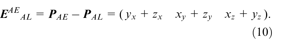
As can be seen from equation (10), the difference between the two tracking models (PAE and PAL) is the lateral dynamic error.
The contour error, calculated using the method developed by Zhang et al., 34 is defined as the minimum distance between the ideal trajectory and the actual trajectory. It can be represented as
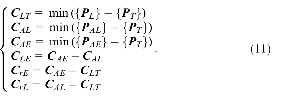
where {
To sum up, the lateral dynamic error of the feed drive system will be coupled into the tracking error of the TCP with the structure and motion relationship of the machine tool and will result in the tracking error and contour error. The tracking error model considering the lateral dynamic error is more accurate in the evaluation of the trajectory error of the TCP. In the high-speed feed drive system, the influence of the structural components’ flexibility on the positioning accuracy increases, and the lateral errors increase. In this case, the lateral dynamic error becomes the non-negligible error component.
In addition, as can be seen from equation (8), the influence of the lateral dynamic error on the tracking error depends on the ratio of lateral dynamic error to axial dynamic error; the quantitative analysis is presented in Section “Sensitivity analysis of the tracking model considering the lateral dynamic error.”
Sensitivity analysis of the tracking model considering the lateral dynamic error
To quantitatively investigate the influence of the lateral dynamic error on the tracking error of the TCP, the Sobol method 35 was used to perform sensitivity analysis on the tracking error model.
The scalar value of the tracking error is obtained by normalizing equation (8):
According to the Sobol method, equation (8) can be decomposed as
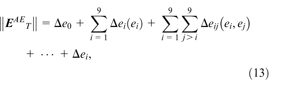
where Δe0 is the mathematical expectation of the tracking error, Δe0(ei) is the tracking error under the action of variable ei, and Δeij(ei,ej) is the tracking error under the action of variables ei and ej. Δei (i = 1, …, 9) is the higher-order term corresponding to the variable ei. ei stands for the variables xx, yx, zx, xy, yy, zy, xz, yz, and zz.
The first-order sensitivity coefficient of equation (11) can be expressed as
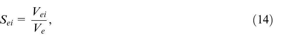
where Ve is the total square deviation and Vei is the partial variance.
The sensitivity coefficients of the variables in the tracking error model were calculated using MATLAB. The Sobol analysis model with nine input variables was employed. The number of samples was set as 10,000. The result is illustrated in Figure 3.
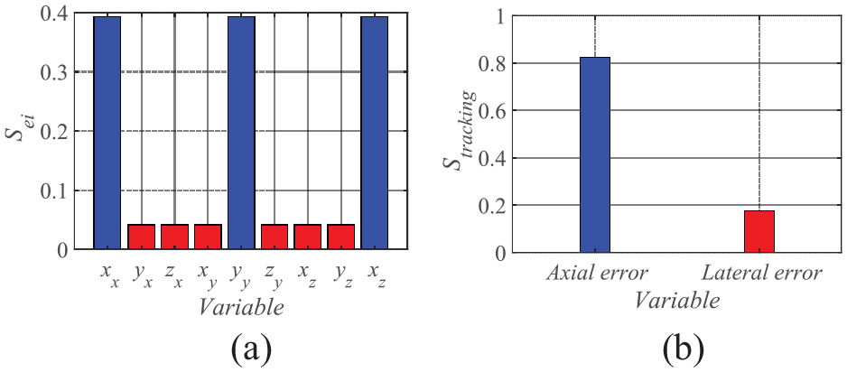
Sensitivity analysis: (a) first-order sensitivity coefficient of each variable and (b) first-order sensitivity coefficient of axial and lateral error.
As can be seen in Figure 3, the axial dynamic error greatly affects the trajectory accuracy of the TCP under the set conditions; however, the influence of the lateral dynamic error cannot be neglected. The first-order sensitive coefficient of the axial errors in the x-axis, y-axis, and z-axis is 0.3932, and the lateral error is 0.0419. For the tracking error, the total first-order sensitivity coefficient of the axial error is 0.8244, and the overall lateral error is 0.1756. When an appropriate error control strategy is employed to reduce the axial tracking error arising from the phase lag and the limitation of the servo bandwidth caused by the servo control to the level of dozens of microns, the lateral dynamic error plays a dominant role in the tracking error of the TCP. Therefore, the lateral dynamic error of the feed drive system affects the trajectory accuracy of the TCP and cannot be ignored, especially in the case of high speed, high acceleration, high precision, and heavy load. To achieve high tracking accuracy, the lateral dynamic error must be considered. Furthermore, the lateral dynamic error should be considered in the reduction or compensation of the tracking error and contour error in machine tools.
Experimental verification
To verify the aforementioned results, linear, circular, and butterfly trajectories were adopted as the input trajectories in the experiments on a three-axis machine tool (Figure 4). A linear encoder was connected to the moving component so that the real-time position of the feed drive system could be outputted. The experimental trajectory was set as 400, 500, and 220 mm for the x-axis, y-axis, and z-axis, respectively. In addition, the actual position of the TCP was determined using the laser tracker. 36 The target is placed successively on the spindle and the workpiece to obtain the positions of the TCP relative to the workpiece function point. The spindle was unloaded and stationary. To eliminate the influence of the static geometric error on the measurement results of the lateral dynamic error, the starting position and stopping position of each feed drive system were determined to obtain the direction vector and the static geometric error were determined when the system move at the speed 0.1 m/min. The static geometric error was then calculated and subtracted from the measurement results of the lateral dynamic error. When the multi-axes are moving simultaneously, the steady-state part of the axial dynamic error is reduced by a pre-compensation method based on the CNC system. Meanwhile, each experiment was repeated three times.
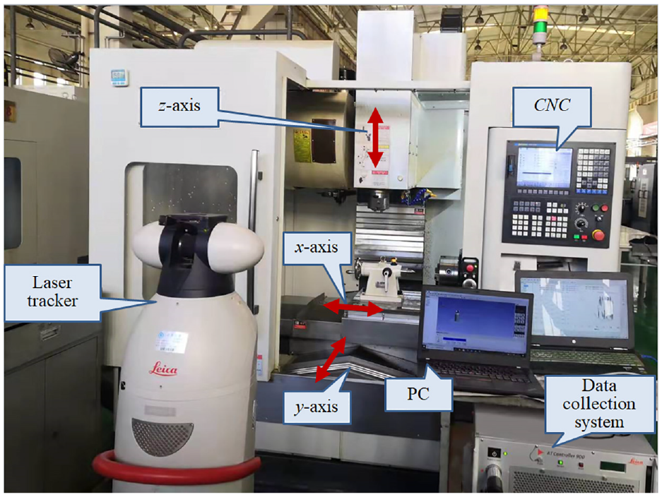
Experiment equipment.
Lateral dynamic error
To investigate the lateral dynamic error, each feed drive system was driven separately with the commanded trajectory, as shown in Figure 5. When one of the feed drive systems is operated at the speed of 2 m/min, the others maintained stationary, and a laser tracker was used for the three-dimensional position tracking of the target point fixed on the corresponding moving component. The results are shown in Figure 6.
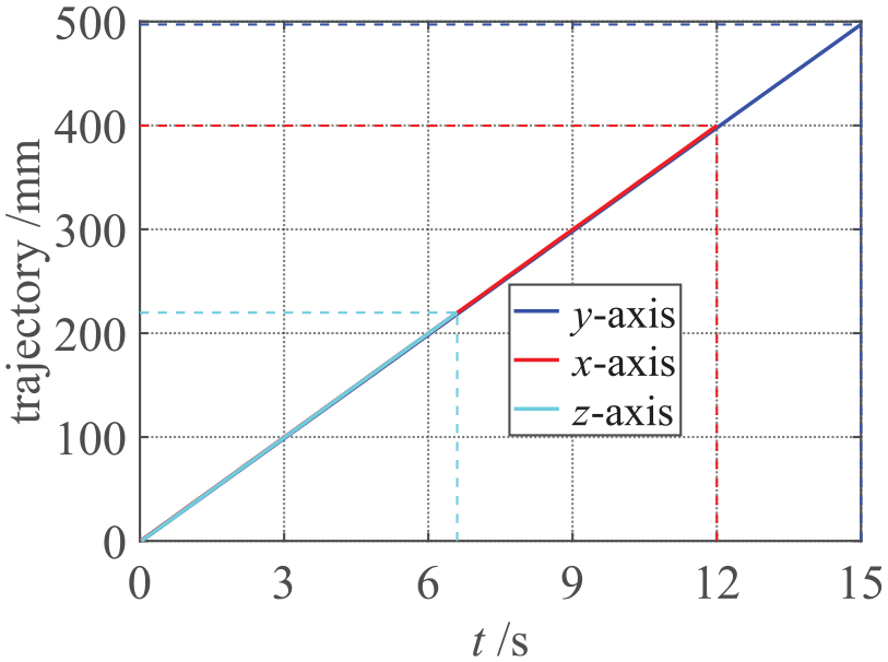
Input trajectory.
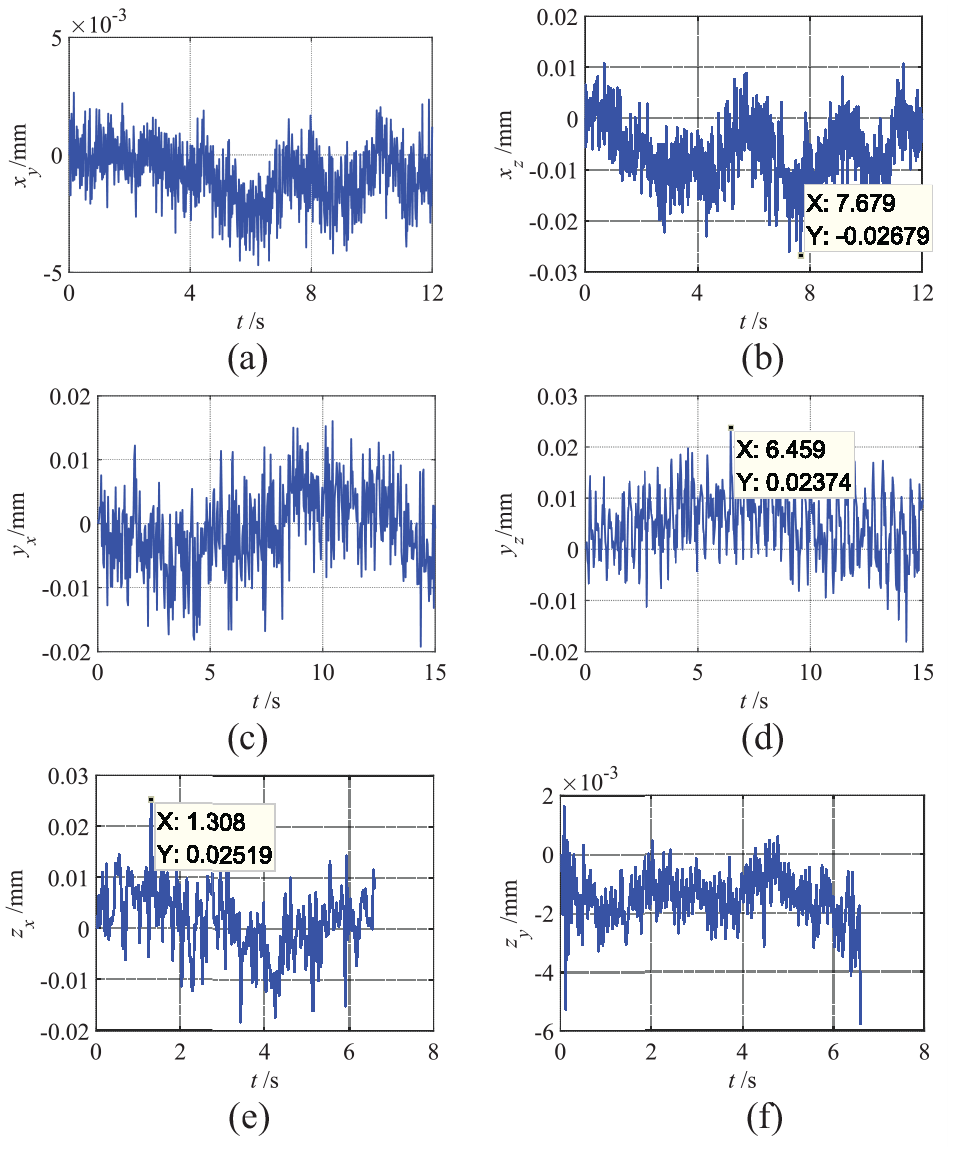
Lateral dynamic errors: (a) lateral dynamic errors of x-axis in y-direction, (b) lateral dynamic errors of x-axis in z-direction, (c) lateral dynamic errors of y-axis in x-direction, (d) lateral dynamic errors of y-axis in z-direction, (e) lateral dynamic errors of z-axis in x-direction, and (f) lateral dynamic errors of z-axis in y-direction.
As can be seen in Figure 6 (a) and (b), when the x-axis moves along the nominal trajectory, the lateral dynamic errors were observed in the y-direction and z-direction, and the maximum value was 0.026 mm. Similarly, when the y-axis moves along the nominal trajectory, the lateral dynamic errors were noted in the x-direction and z-direction, and the maximum value was 0.024 mm (Figure 6(c) and (d)). When the z-axis moves along the nominal trajectory, the lateral dynamic errors occurred in the x-direction and y-direction, with a maximum value of 0.025 mm (Figure 6(e) and (f)). The lateral dynamic errors of the x-axis in the z-direction are smaller than in the y-direction because the stiffness in the z-direction of the x-axis is better. Similarly, the lateral dynamic errors of the z-axis in the y-direction are greater than in the x-direction. Whereas, the lateral dynamic errors of the y-axis in the x-direction and z-direction are almost equal. Different from the lateral geometric error, the lateral dynamic error has obvious vibration characteristics. Considering the value of the lateral dynamic error, it can not be ignored for precision machine tools.
The influence of lateral dynamic error on trajectory error
Circle trajectory
A circle trajectory was designed to analyze the influence of the lateral dynamic error on the trajectory error. As shown in Figure 7(a), SP is the ideal trajectory, while SA and NC represent the actual trajectories determined using the laser tracker and linear encoder, respectively. The speed was set as 2 m/min. Figure 7(a) depicts the tracking errors along the x-axis and y-axis determined using the laser tracker and linear encoder, respectively. Figure 7(b) illustrates the lateral dynamic errors of the endpoint of the biaxial motion system determined by the laser tracker. Figure 8 shows the contour errors of the endpoint along the x-axis and y-axis determined using the laser tracker and linear encoder, respectively.
Tracking errors: (a) tracking errors of x-axis and y-axis and (b) lateral dynamic error of x-axis and y-axis in z-direction.
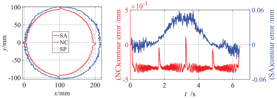
Trajectory tracking: (a) trajectories from SA, NC, and SP and (b) contour errors from SA and NC.
It can be seen from Figure 7(a), the tracking error of the x-axis and y-axis determined using the laser tracker differs from using the linear encoder. This is because of multiple reasons. First, the dynamic error outside the servo loop leads to the tracking error determined using the laser tracker to be greater than determined using the linear encoder. Second, due to the cross-axis coupling influence and the y-axis being a greater distance from the tested point, the tracking error of the y-axis is larger than x-axis. Third, the lateral dynamic error of the x-axis in the y-direction is concluded in the tracking error of the y-axis in the tested data from the Laser tracker; similarly, the lateral dynamic error of the y-axis in the x-direction is concluded in the tracking error of x-axis. Figure 7(b) shows the lateral dynamic error of the x-axis and y-axis in the z-direction during the simultaneous moving. It can be seen from Figure 7(b)xyz is larger than the xz or yz, but it is not a simple accumulation of two types of lateral dynamic errors.
For ease of observation, the contour error was magnified 2000 times (Figure 8(a)). The measured value of contour error for the circular trajectory obtained using the laser tracker differed from using the linear encoder. Data from SA exhibited an undercut in the right half, while data from NC exhibited overcut in the whole circle except the quadrant location. The vibration of SA was stronger than of NC, thereby resulting in more drastic tool damage and vibration marks on the workpiece surface. Meanwhile, in the start and end segments of the circular trajectory, the measured value of contour error obtained using the laser tracker was smaller than using the linear encoder (Figure 8(b)), but the situation was opposite in the middle area because of the coupling influence of the tracking error between x-axis and y-axis.
It is especially pointed out the cross-axis dynamic coupling is not considered in this study. Two types of coupling relationships in the multi-axis motion system: structural coupling and dynamic coupling. By comparing Figure 8 and the measurement results from the studies by Hu et al. 29 and Yang et al., 37 it can be seen that the influence of dynamic coupling is less than of the lateral dynamic error in structural coupling. So, this paper focuses on the influence of the lateral dynamic error on the tracking error and contour error in structural coupling. In terms of dynamic coupling, Yang et al. 37 and Wang et al. 38 main focus is on the cross-axis dynamic coupling.
Butterfly trajectory
A butterfly trajectory was designed as the commanded trajectory of the TCP to analyze the influence of lateral dynamic errors on the trajectory errors of the three-axis machine tool. The speed was set as 2 m/min. The ideal and actual trajectories are shown in Figure 9 (the contour error is magnified to 100 times), whereas Figure 10 shows the actual position of the feed drive system determined using the laser tracker (the tracking error is magnified to 50 times). As shown in Figure 9, SAL is the trajectory without the lateral errors xyz, zx, and zy, whereas SA is the trajectory with all the lateral errors. NC is the trajectory from the linear encoder, and SP is the commanded trajectory. Moreover, a visible difference was noted between NC, SAL, and SA.
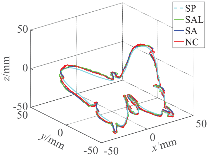
Butterfly trajectory.
Because of the movement along the x-axis and y-axis simultaneously, a correlation exists between the positions of the x-axis and y-axis measured using the laser tracker. The lateral dynamic error of the x-axis in the y-direction is correlated with the y-axis motion, while the lateral dynamic error of the y-axis in the x-direction is correlated with the x-axis motion. Therefore, the test results as shown in Figure 10 can be expressed as:
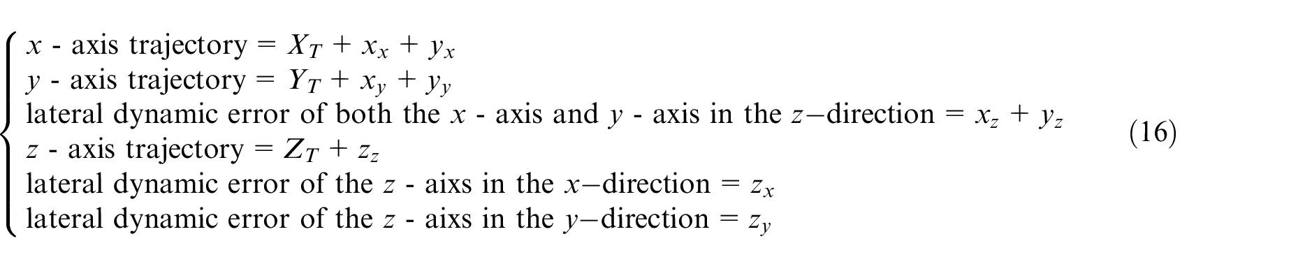
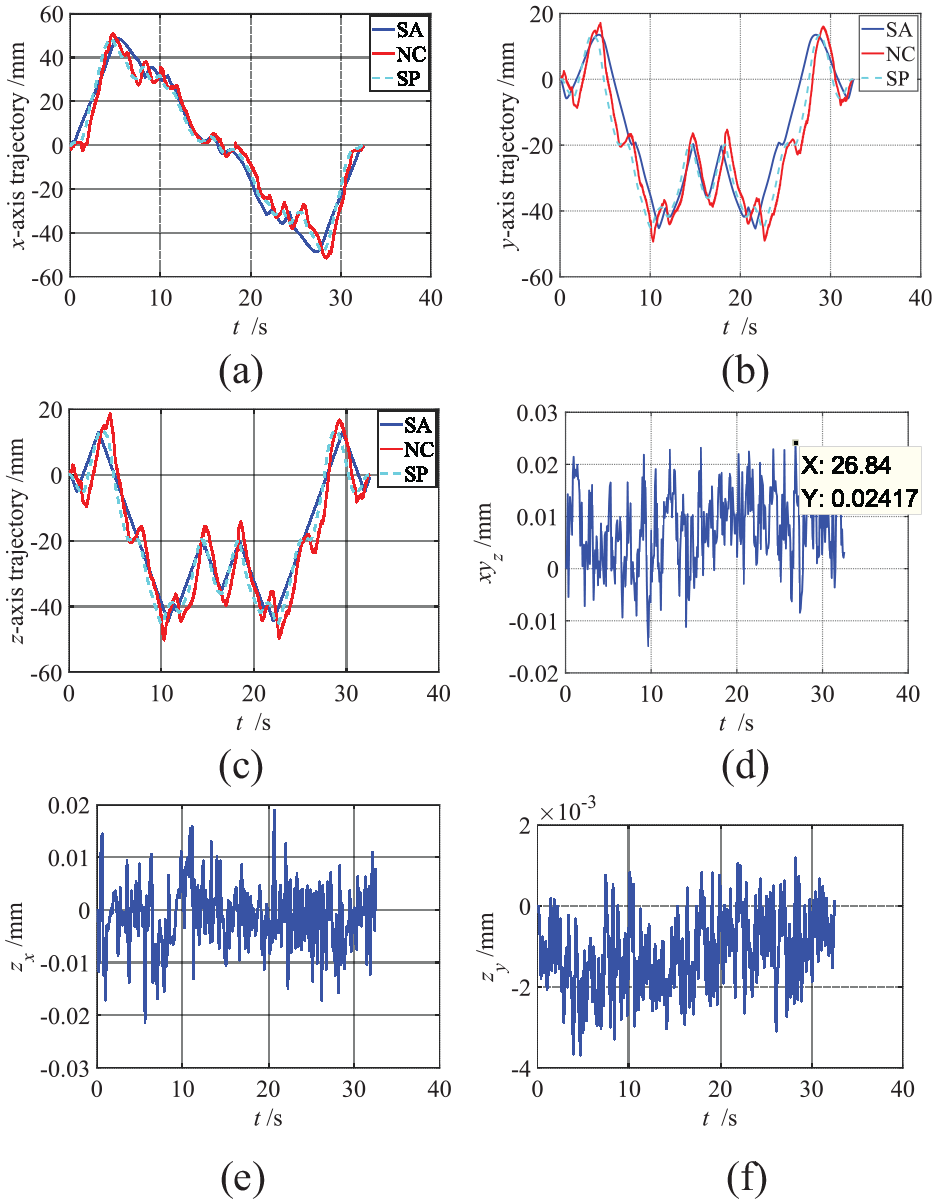
Tracking errors and lateral dynamic errors: (a) x-axis trajectory, (b) y-axis trajectory, (c) lateral dynamic error of x-axis and y-axis in z-direction, (d) z-axis trajectory, (e) lateral dynamic error of z-axis in x-direction, and (f) lateral dynamic error of z-axis in y-direction.
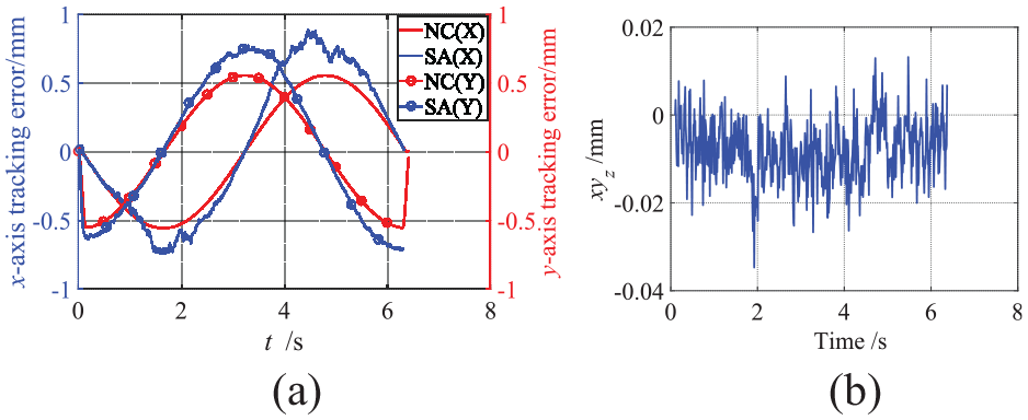
As shown in Figure 10(a) to (f) are the xx, yy, zz, xyz, zx, and zy, respectively. The lateral dynamic error can reach a maximum of 0.024 mm, which resulted in about a 0.25 mm difference between the tracking error of SA and NC, as shown in Figure 11(a). Thus, lateral dynamic errors should be considered when modeling, estimating, or compensating for tracking errors in a multi-axis motion system.
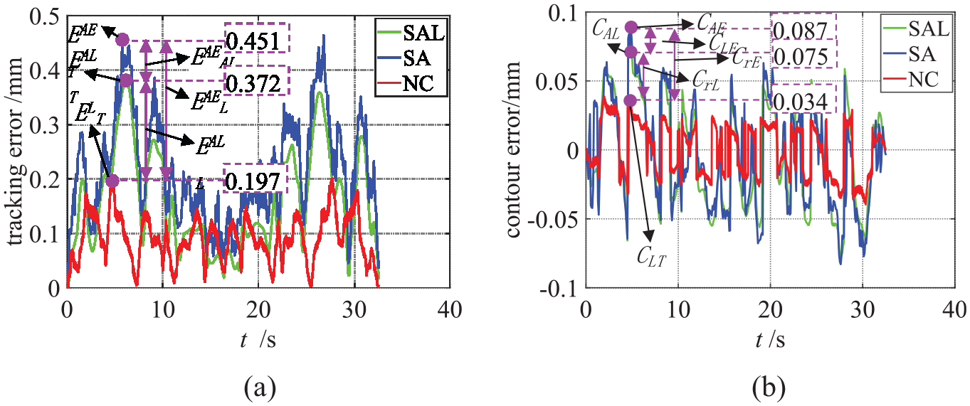
Tracking errors and contour errors: (a) tracking errors and (b) contour errors.
The maximum tracking error EAE T , EAL T , and EL T was 0.451, 0.372, and 0.197 mm, respectively (Figure 11(a)). The lateral dynamic error resulted in a deviation between EAE T and EAL T (EAE AL = 0.079 mm) and accounted for 17.52% of the total tracking error, and is consistent with the model prediction of 17.56% in “Sensitivity analysis of the tracking model considering the lateral dynamic error” A little difference is caused by the dynamic coupling and superposition relationship between axes. The axial dynamic error outside the servo loop resulted in a deviation between EAL T and EL T (EAL L = 0.175 mm) and accounted for 38.8% of the total error. Furthermore, the dynamic error outside the servo loop resulted in a deviation between EAE T and EL T (EAE L = 0.254 mm) and accounted for 56.3% of the total error. Thus, the ideal pre-compensation of the TCP tracking error should be calculated using EAE T . The tracking error without considering the lateral dynamic error is 82.48% of considering the lateral dynamic error. Therefore, the tracking error considering the lateral dynamic error is more accurate.
The contour error determined by the laser tracker differed from using the linear encoder (Figure 11(b)), reaching a maximum value of 0.087 mm of the SA, whereas NC was 0.034 mm. This is not allowed for high-precision machining. The lateral dynamic error resulted in a deviation between CAE and CAL (CLE = 0.012 mm) and accounted for 13.8% of the total contour error. The contour error without considering the lateral dynamic error is 86.21% of considering the lateral dynamic error. Therefore, the contour error considering the lateral dynamic error is more accurate. In addition, peaks were observed in the lateral dynamic error, tracking error, and contour error of the TCP at the location of small curvatures and reverse (Figures 10 and 11). The reason is the acceleration increases and changes rapidly. The lateral dynamic error is mainly related to the dynamic characteristics of the feed drive system, the flexibility of structural components, assembly, and disturbance. Thus, when studying the dynamic characteristics of feed drive systems, we should pay attention to the axial dynamic characteristics as well as the lateral dynamic characteristics.
Conclusions
In this study, the influence of the lateral dynamic error of the feed drive system on the TCP trajectory error of the multi-axis motion system was investigated. By comparing the tracking error models of the three-axis machine tool with and without lateral dynamic error, and combing sensitivity analysis, it is confirmed the lateral dynamic error has an important effect on the trajectory error of the TCP. Furthermore, linear, circular, and butterfly trajectories were designed to perform experiments on a three-axis machine tool to verify the results. Subsequently, the conclusions are drawn as follows:
The lateral dynamic error is defined as the time-varying dynamic deviation perpendicular to the motion direction. Different from the lateral geometric error, the lateral dynamic error has obvious vibration characteristics. The lateral dynamic error of the feed drive system reached a maximum of 0.026 mm.
The tracking error model considering the lateral dynamic error can predict the trajectory error of the TCP more accurately. The tracking error and contour error without considering the lateral dynamic error is 82.48% and 86.21% of considering the lateral dynamic error. The sensitivity analysis based on the tracking error model and the experimental results show the tracking error caused by the lateral dynamic error accounts for 17.56 % and 17.52% of the total error of the TCP. The lateral dynamic error results in overcut and undercut, tool damage, and deteriorating workpiece quality.
The lateral dynamic error increased at the location of small curvatures and the reverse of the trajectory. The influence of lateral dynamic error on the tracking error and contour error reached a maximum of 0.079 and 0.012 mm, respectively, thus indicating the lateral dynamic error should be considered in the process of modeling, prediction, and compensation of the TCP trajectory error of multi-axis motion system.
The results reveal the lateral dynamic error is difficult to compensate for and must be suppressed as much as possible by design method or control strategy. For multi-axis systems, the lateral dynamic error should be considered in the trajectory error of the TCP to provide a way to estimate and compensate for the machining progress. In addition, the influence of lateral dynamic error and dynamic coupling error on the trajectory error is correlated and further research on the control and compensation of the tracking error and contour error is required.
Footnotes
Appendix
Declaration of conflicting interests
The author(s) declared no potential conflicts of interest with respect to the research, authorship, and/or publication of this article.
Funding
The author(s) disclosed receipt of the following financial support for the research, authorship, and/or publication of this article: This work was supported by National key research and development program of China (Grant no. 2017YFE0111300) and the National Key Science and Technology Project (Grant no. 2017ZX04013001).