
Abstract
Five-axis hybrid machine tools are widely used due to the advantages of high speed, high precision, and good performance in the aviation and aerospace manufacturing industry. Many scholars have studied the basic theories and key technologies along with the widespread attention of academia and industry thereon. An integrated geometric error modelling method, under the unified coordinate system framework for a general five-axis hybrid machine tool based on a 3-
Introduction
Parallel mechanisms have been widely applied in the manufacture of aviation and aerospace industry components with high speed, high precision, good dynamic performance, and other advantages. Some of the typical mechanisms include the Tricept series module, 1 the Exechon hybrid module, 2 the Sprint Z3, 3 and so on. Tianjin University in China has also developed an excellent parallel spindle head A3.4,5 The Sprint Z3 parallel spindle head has three axial linear guide rails spaced evenly around the static platform, with sliding blocks on the guide rails which can be driven back and forth by a servo motor; the sliding block and the spherical joint on the moving platform are connected by the follower lever. This topology gives the spindle head three motions, a translation along the Z-axis and two swinging motions on the A/B-axis through the movement of three branch chains along the Z-axis direction. DS-Technology developed the ECOSPEED series 5-axis high-speed machining centre by combining a Sprint Z3 with a traditional X-Y workbench. The Sprint Z3 has been widely used in the high-speed and high-precision machining of large-scale structural components in the aviation and aerospace industry.
Geometric accuracy is one of the important performance specifications of the parallel mechanism based spindle heads as the high accuracy are the essential requirements: the accuracy of a parallel mechanism is mainly improved in two ways – accuracy design and kinematics calibration. In theory, the position error at the end of a 6-degrees of freedom (DOF) parallel mechanism can be compensated by software, but for lower-mobility parallel mechanisms, only those position errors corresponding to the degrees of freedom can be compensated through kinematic calibration, the remaining errors can only be controlled by accuracy in design.6,7 The error model is the foundation of accurate design and kinematic calibration. In recent years, many scholars made great advances in error modelling of parallel mechanisms.
One of the classical error modelling approaches is the small perturbation method of homogeneous transformation matrices based on the Denavit-Hartenberg 8 (D-H) conventions, the approach can accurately express the physical significance and accumulation effect of the error sources and there is no tedious matrix differential operation in the process of error modelling. Yao et al. 9 established a static position and orientation error model for a wheeled train uncoupling robot based on this method, analysed the impact of parameter error on position error, and used the input motion planning method to improve the positional accuracy of the robot. The error model for a hybrid parallel robot is proposed by Wang et al. 10 using the same method, and kinematic calibration and error compensation were researched on that basis; however, the parameters become discontinuous when this method is used to research parallel adjacent axes. 11 To avoid this disadvantage, many scholars have proposed different improved models, such as the CPC-Model and S-Model, 12 Sung and Lu 13 analysed a five-axis machine tool using a kind of improved D-H method.
Differential geometry is another effective method used for modelling errors in series and parallel manipulators. Chen et al. 14 introduced a kinematic calibration method based on the local POE error model. The advantages of a POE method lie in the following: (1) revolute and prismatic joints can be uniformly expressed in the twist coordinates, (2) the twist coordinates of the joint axes can be set up with simple values, and (3) it needs no special treatment when two adjacent joint axes are parallel. Based on the same theory, Cheng et al. 15 built error model of a five-axis NC machine tool, and analysed global sensitivity of volumetric errors using a Morris approach. This POE model can compare the error rate effectively, and describe the non-linear relationship between the errors with less computational effort. It is also precise and succinct enough to express the relationship of each of components as the Morris method is based on the elementary effect (EE).
The vector chain method is a kind of commonly used error modelling method. With this method, Ni et al. 16 established an error model for a 3-PRS parallel machine tool based on perturbation principles. Cheng et al. 17 developed an error model of PKM based on the vector chain method, and established the system sensitivity model using statistical methods, considering all of space error terms. Huang et al.18,19 established an error model for a hybrid machine tool using the vector chain method, and introduced kinematic calibration based on a regularisation method; the merit of this method lies in the identification model being concise and effective, and it just requires measurement of the partial degree of freedom in the direction of movement to run. In addition to the above error modelling methods, screw theory is also a useful approach for establishing an error model. Jin and Chen 20 proposed an error model based on screw theory which can be used to analyse three types of constraint error problems of decoupled parallel manipulator.
On the basis of the basic modelling method, many scholars established PKM error models considering connection errors, guide errors, and clearance errors. For lower mobility parallel mechanisms such as the 3-
Although the above error modelling methods have many advantages, they fail to analyse the geometric error sources in the view of manufacturing and assembly. Huang et al.27,28,29 proposed an effective error modelling method which enables the source errors affecting the compensable and non-compensable pose errors to be separated in an explicit manner, and then used it for the tolerance design of a 2T1R parallel manipulator. However, the generality of this method is quite poor. On this basis, Liu et al. 30 developed an error modelling method based on screw theory, this method can separate the various geometric error sources with the characteristics of twist space, wrench space, and their sub-space as a constrained body in the configuration space. It can be used to generalise lower-mobility parallel manipulators. Tian et al. 31 used this approach to a 3-RPS parallel spindle head, but this method cannot realise the rapid and effective separation of error sources when it is used on a hybrid machine tool. Therefore, it is essential to establish a comprehensive error model which can distinguish the compensable error sources from those non-compensable error sources affecting the positional accuracy of the end-effector.
Those scholars mentioned above have conducted extensive research in the field of accuracy analysis of parallel mechanisms, but further research is needed in the area of error modelling method and the error source separation. On the basis of previous research results, this work proposes an integrated error modelling method for the general 3-PRS-XY hybrid machine tool, and analyses the various error sources affecting position errors of the end-effector from the perspective of manufacturing. This method can separate the compensable and non-compensable error sources affecting the accuracy of the end-effector, and it is critical for the further accurate design and kinematic calibration of such a hybrid machine tool.
Kinematic analysis
Structure description
The research object of this article is a five-axis hybrid machine tool consisting of a 3-
The 3-

Structural model of the 3-
The static platform-workpiece kinematic chain, a two freedom mechanism, is composed of a vertical (Y-direction) gantry double drive moving platform and a horizontal (X-direction) moving platform (Figure 2). The five-axis linkage machining centre with its hybrid structure can not only guarantee the stiffness at the end of machine tool but also expand the workspace thus maximising the machining efficiency of aviation industry workpieces with complex shapes.

Equivalent schematic diagram of the mechanism.
The 3-
Position inverse kinematics
A position inverse solution can establish the mapping relationship between the position and orientation of the end-effector and the kinematic chain joints variables. The 3-

where,
Taking the dot product with

Similarly, taking the dot product with

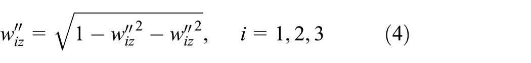
Uniting equations (2) and (3) gives
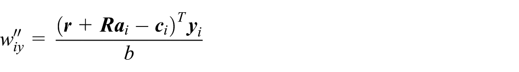

Then

Error model
The error model for the 3-PRS parallel spindle head and the X-Y serial workbench is established based on the theory of vector chains and small perturbations: an integrated error model of a hybrid machine tool is then established.
Error model of a 3-P RS parallel spindle head
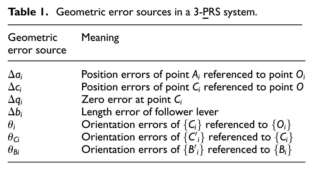
Error source analysis
The 3-
Geometric error sources in a 3-
Error model
The error model is established based on the theory of small perturbations. Taking the perturbation of the position vector equation of tool nose point in the end-effector gives
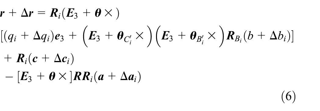
Where,
Taking the linearization of equation (6) and subtracting it from the nominal position vector of the tool nose point and omitting the high-order items gives

Left-multiplying equation (7) by
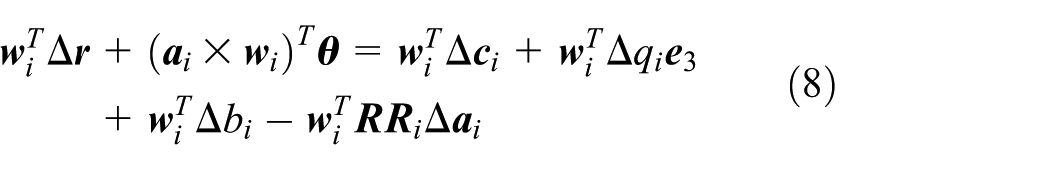
where
Left-multiplying equation (7) by
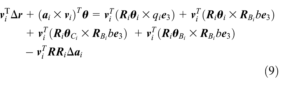
Where,
Rewriting and simplifying equations (8) and (9) in matrix form yields

where
Error model of an X-Y workbench
Error source analysis
The geometric error sources of an X-Y workbench mainly come from the movement of the single rail and the relative errors between the guide rails. All possible geometric errors of an X-Y workbench are shown in Table 2.
Error sources of an X-Y workbench.

Error model
A closed-loop equation for an X-Y workbench can be expressed as

where
Perturbation of equation (11) leads to
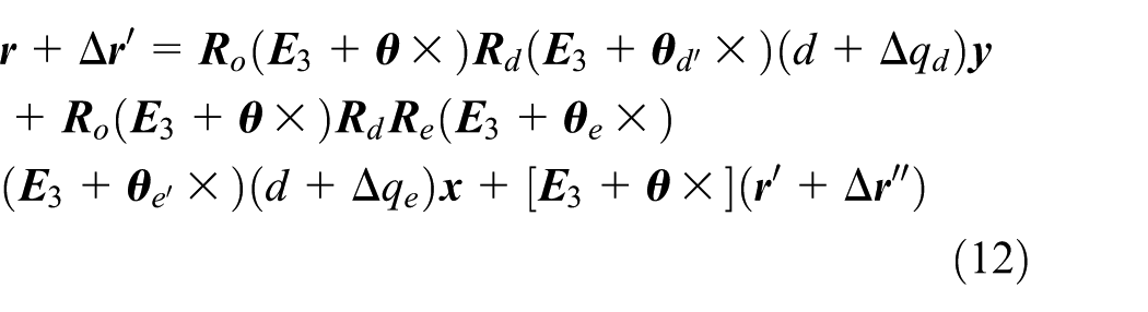
Simplifying equation (12) and omitting the higher-order items, subtraction from equation (11) leads to

All axis directions of coordinate system
Rewriting equation (13) in matrix form yields

where

Total error model
The 3-

Rewriting equation (15) in matrix form leads to

where
Isolation of error sources
The topology of the machine tool is divided into the parallel and the serial components, and the parallel mechanism can be also divided into a six-DOF type and a lower-mobility type. Theoretically only the position errors at the end of the mechanism corresponding to the degree of freedom of machine tool can be compensated by an NC system.
For the lower-mobility parallel mechanisms, errors in the actuation space can be compensated, but not in the constraint space. There is no direct mapping relationship between the non-compensable error sources and the movement of the end-effector in three-dimensional space for the serial mechanism, therefore, screw theory can be employed to solve this problem, which can form a twist space and a wrench space by increasing the number of dimensions in the space. Then the error sources can be separated according to the limited relationship in that space.
The Jacobian matrix and screw theory are used to analyse the error source separation for both parallel, and serial machine tools. The various types of error sources of such hybrid machine tools are separated based on these two theories.
Error source isolation methods for the parallel mechanism
Theoretical basis
The Jacobian matrix of the parallel machine tool can be divided into a driving Jacobian matrix
Application
The theory can be used in the 3-

Corresponding error terms can be expressed as

This comprises the non-compensable error sources. Because there is a zero term in the Jacobian matrix, the corresponding error sources have no effect on the orientation error, thus the model of error can be simplified to


So far, all compensable error sources and the non-compensable error sources of the 3-
Error source isolation methods for the serial mechanism
Screw theory
There is no simple mapping relationship between the non-compensable error sources and the degrees of freedom in the serial machine tool. So screw theory is needed to expand the three-dimensional space to a special six-dimensional space. The machine tool error, and the error sources, can be expressed by six-dimensional vectors, in which the error source could be separated.
Twist and wrench
Expressing the unit twist and wrench with Plücker coordinates based on a reference point on the end of the machine tool movement chain, and measuring them in the coordinate system at the end of the machine tool, the results can be expressed as

where
Twist space and wrench space
Within the machine tool working space, the set of error sources can be expressed in six-dimensional space, with the twist space signed with T. The force and torque acting on the end of the machine tool can be also expressed in six-dimensional space, as the wrench space signed W. T and W have a dual relationship.
On the translation axis of the machine tool, the basis of
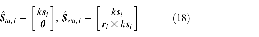
As for the axis of rotation, the basis of

where
Error source isolation methods
Under the permitted twist sub-space, the error screw of the machine tool can be expressed as

where
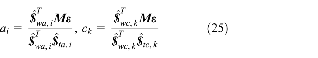
Taking the dot product with


Using the same operation on the equation


where
Combining equations (23) and (24) leads to
The machine tool error model, after isolating the compensable error sources and non-compensable error sources, can be expressed in matrix form as


where
Application
Concerning the serial structure X-Y workbench of the 3-

The basis of its wrench space can be expressed as

Where,
For the static platform, the workpiece error model built in the last section is in vector form, but it can be transformed into screw form. Establishing a workpiece-XY platform error model, the transformation between the coordinate system of each axis can be established as

where

Taking account of the error source of each axis, and measuring each error source in the terminal coordinate system

In a position on the workspace,
In equation (29), A is the accompanying transformation matrix between adjacent coordinate systems: here, it is the unit matrix.

Equation (30) can be expressed under the permitted twist sub-space as

The end-effector error screw of the serial kinematic chain can be expressed as a linear combination of two types of geometric error sources, each error source can be translated to a linear explicit expression with physical meaning. The error model of the static platform-workpiece can be written in matrix form as

where,

Combining it with the error model of the static platform-tool gives

Taking the dot product to equation (33) with

Through the aforementioned error separation analysis, non-compensable error sources include the following parts: the roll angle error
Sensitivity analysis
The global index of sensitivity is proposed and the effects of orientation error of the end-effector, arising from each error source, are analysed. The influence of various error sources on the end-effector was confirmed. The error sources can be separated into those for which no compensation was possible, and those where it was; the former can be controlled during the manufacturing process and the latter can be improved by kinematic calibration. The use of the proposed method may assist in the design and manufacture of similar equipment.
Considering the effects on terminal position and orientation accuracy arising from the non-compensable errors statistically, a sensitivity probabilistic model can be established as

Where,

The global sensitivity evaluation index of volumetric error

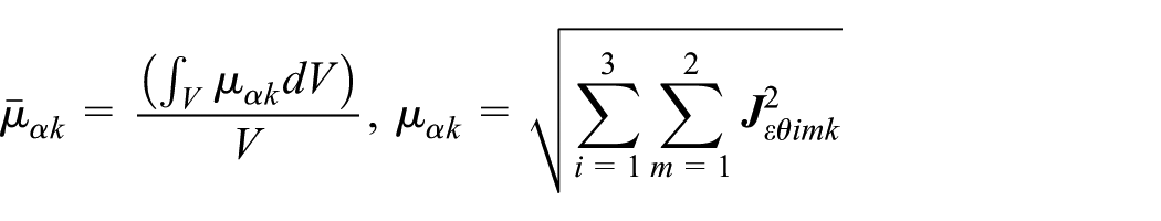

where V is the volume of a design space,
Nominal, and work space, parameters of the 3-PRS spindle head.

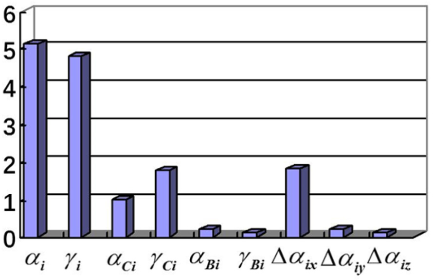
Figures 3–5 show the sensitivity analysis of the volumetric error

The sensitivity of volumetric error with respect to
The sensitivity of verticality error with respect to

The sensitivity of angular error with respect to
Figures 6–9 show the result of the sensitivity analysis of the X-Y platform, where

The sensitivity of the X-direction coordinate with respect to
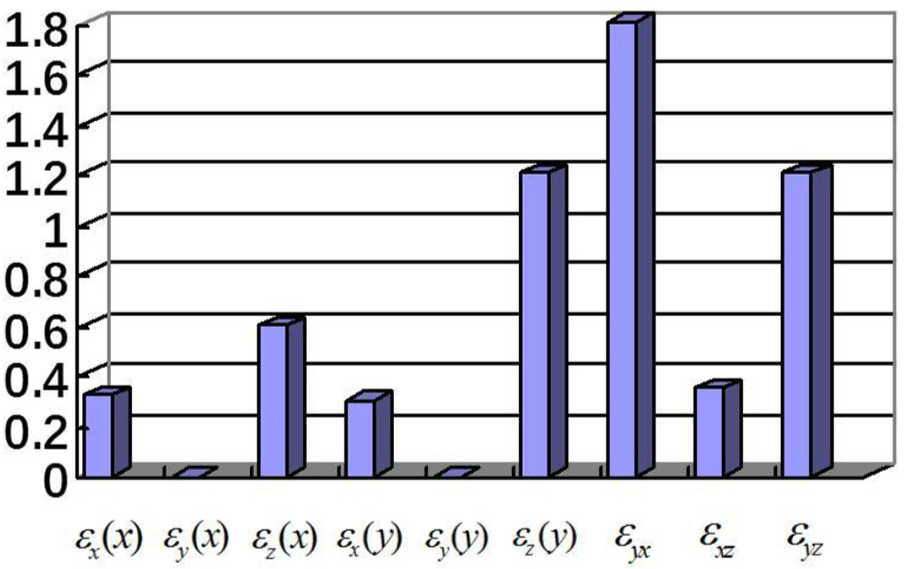
The sensitivity of the Y-direction coordinate with respect to

The sensitivity of the Z-direction coordinate with respect to

The sensitivity of volumetric error with respect to
After investigating the trend in each sensitivity measure to changes in the length of the follower levers, the influence of the follower lever length on machining accuracy can be ascertained. Figures 10 and 11 show the changes in the sensitivity coefficient of the volumetric error

The change in volumetric error sensitivity with respect to

The change in verticality error sensitivity with respect to
It can be seen from these two figures that, with the change of the follower lever length from 300 mm to 360 mm, the change in sensitivity coefficient can be described as quasi-linear, and only the sign of the gradient and intercept are different. The rates of change of the volumetric error
Rate of change of error source sensitivities.

Conclusion
The machine tool kinematic chains consist of the static platform–tool chain (parallel chain) and the static platform-workpiece chain (serial chain). The error model for the 3-
The error source separation methods are analysed for different topologies of machine tool. The Jacobian matrix and screw theory are used to analyse the error source separation for both parallel, and serial, machine tools. The various types of error sources of such hybrid machine tools are separated based on these two theories.
The probability model of the sensitivity of non-compensable error sources is established statistically. The global index of sensitivity is proposed and the effects of orientation error of the end-effector, arising from each error source, are analysed.
The manufacturing-oriented and integrated geometric error model proposed in this article provided a theoretical foundation for sensitivity analysis: the influence of various error sources on the end-effector was confirmed. The error sources can be separated into those for which no compensation was possible, and those where it was; the former can be controlled during the manufacturing process and the latter can be improved by kinematic calibration. The use of the proposed method may assist in the design and manufacture of similar equipment.
Footnotes
Appendix 1
Handling Editor: James Baldwin
Declaration of conflicting interests
The author(s) declared no potential conflicts of interest with respect to the research, authorship, and/or publication of this article.
Funding
The author(s) disclosed receipt of the following financial support for the research, authorship, and/or publication of this article: This research was supported by a National Natural Science Foundation of China grant (No. 51575385) and a Natural Science Foundation of Tianjin grant (No. 16JCZDJC38400).