
Abstract
This article applied the rigid-plastic finite element software, DEFORMTM-3D, to investigate the cutting plastic deformation behavior of 6061 aluminum alloy. The main design contained a variety of different geometric types of chip breakers for turning tools. There were three kinds of geometries for chip breakers in our design: the first one is an ordinary cutting tools provided without chip breaker, the second one is a squared concave contour, and the last one is an elliptical concave contour. For the purposes of analyzing the equivalent stress, strain, temperature, and wear of cutting tools after machining, a series of simulations were performed according to the three different geometric chip breaker designs that operated under the same turning conditions. The results of simulation analysis could assist the engineers to confirm the applicability of finite element method for cutting 6061 aluminum alloy. The article found that the squared-type chip breaker generated the maximum wear at the chip breaker area, and the elliptic chip breaker induced homogeneous wear at the tip area.
Introduction
Cutting is an important method for shaping a metal material into a designed conformation, under the demand of improving the processing efficiency and product surface quality, together with the stringent requirements of marketing. We have to examine many cutting inherent principles since the metal cutting technology is quite complex and involves many factors and parameters. The analytical methods are difficult to describe the chip forming process accurately, and the purely experimental study requires a lot of investment and time. The finite element (FE) analysis technique plays a helpful role as an effective tool to assist the engineers in their research and development efforts. In the analysis of machining process, it can provide information about the workpiece material properties, plenty of analysis data such as temperature distribution, stress, strain and strain rate functions, and so on, for the interaction between the various machining parameters.
In the beginning, we had reviewed some literatures about the machinability. Toru et al. 1 used a cutting tool heated with induction heating to research the thermally assisted machinability of yttria-stabilized tetragonal zirconia polycrystal (Y-TZP) which is an engineering ceramic. They conducted an analytical simulation for estimating the rise in workpiece temperature during the process. And the cutting experiments demonstrated an improvement in its cutting machinability. Stepan et al. 2 implemented two principally different methods: semi-discretization and multi-frequency solution. Both provided reasonably identical stability charts. The comparison of three different helical milling tools of identical cylindrical geometry showed that the serrated tool provided the most significant improvement in cutting stability. Gandjar et al. 3 applied an analytical method for cutter-workpiece engagement (CWE) calculation in five-axis milling and proposed two types of cutters: flat-end and toroidal cutters in their research that is applicable for semi-finish milling. Totis et al. 4 researched about the tools’ geometry optimization, workpiece material characterization, process monitoring, and their optimization which are based on the measurement of cutting forces using machining dynamometers. Experimental results proved the excellent characteristics of the new device and its effectiveness for investigating advanced machining applications. Jaroslava and Zdenk 5 dealt with the influences of cutting edge preparation and cutting edge radius on tool life, cutting forces, and the roughness of machined surface during finishing machining of ferrite–martensite stainless steel.
Ivana and Miroslav 6 researched the cutting tool operated in the processing process and measured the parameter of cutting edge to guarantee their reliability and repeatability. Adriano and Adriane 7 suggested some correct measuring parameters on the cutting edge such as radius of the cutting edge, K factor, and roughness of the surface, chipping, and their evaluation when machining special alloy Inconel 718 which is used mainly in the aerospace industry. Miroslav et al. 8 showed a monitor during the machining optimization process. The main focus was on different cutting edge radiuses where polishing methods and standard finishing surface processes were used. If we want a complex view of the cutting tool and cutting process, it is necessary to use suitable devices and correct measuring methods. Klocke et al. 9 described the application of stationary force measurement platforms for five-axis milling processes with compensated force signals. They focused on the scientific and technical challenges for the development of an appropriate measurement system for five-axis milling processes. The main technical challenges were the compensation of the dynamic forces, the consideration of the gravity force, and the changing mass due to the metal cutting process. Seyed and Victor 10 presented the effects of cutting parameters on friction angle and the correlation between friction angle and exit up milling side burr thickness during slot milling of aluminum alloys. Experimental results show that lower friction angle is obtained when larger chip load was used. Consequently, larger friction angle was obtained when exit up milling side burr thickness decreased and exit bottom burr thickness increased. Paul et al. 11 studied that tool vibration is a frequent problem in the manufacturing industry while metal cutting process takes place. It affects the surface finish of the work piece, tool life, and results in irritating noise. David et al. 12 offered the most appropriate cutting options (based on the requirements of the workpiece) that allow a non-expert user to select the most appropriate process with emphasis on a predefined priority: finish, cost, or time.
This article used rigid-plastic FE DEFORMTM-3D software to study the plastic deformation behavior of 6061 aluminum alloy during the cutting process. The results of simulation analysis aimed to confirm the applicability of FE method for cutting 6061 aluminum alloy.
FE analysis
In this study, by referencing the DEFORM™-3D User’s Manual,13,14 details of the current modeling capabilities that are available in DEFORMTM-3D system can simulate the three-dimensional (3D) metal cutting environment in turning process without any assumptions that are associated with orthogonal cutting conditions. These modeling procedures enable the engineer to study the process response for any changes in process conditions. Computations of cutting forces, cutting temperatures, chip shape, tool wear, and tool life can be performed using this system. The engineer studied the effect of process parameters such as cutting speed, feeding rate, and depth of cut on the process response. DEFORMTM-3D supports a special purpose template that can expedite the setup procedures of the simulation model and has coherence with the same engineering language of process engineer.
FE model
In metal-shaping process, the occurrence of flaw is caused mainly due to the influence of the plastic deformation under the surface and the material ductile fracture by processing. The brittle failure of metallic material among crystallizing cleavage surfaces, the atom unifies to destroy for the focus micro phenomenon mutually, namely breaks out the destruction (cleavage fracture), and before the material destroys, the strain capacity of having does not have minimum even the plastic deformation, and formation destruction of non-early warning; But the ductile fracture belongs to the shear that the crystallization slipping is the result to destroy (shear fracture). Revises in view of the Cockcroft and Latham criterion (C&L), schedule a dimensionless (non-dimensional) judging criterion formula to call the normalized C&L criterion ductile fracture criterion (refer to equation (1))

where σmax is the maximum principal stresses,
Stress is the measurement of force applied on unit area. This variable is important in metal forming because the amount of deformed material depends on how much stress was subjected to the workpiece. There are several definitions of stress, and strain is a metrological terminology of the total accumulated deformation. Each material presents a unique characteristic stress–strain curve that determines how the material behaves structurally. For most isotropic metals, this behavior appears as a general shape as shown in Figure 1. Note that the top and bottom curves are the engineering stress–strain curves for materials, and the middle curve is the true stress–strain curves for a given material. The true stress–strain curve is the same for either tension or compression, but they are not the same in terms of engineering stress and strain.

Stress and stain curve in 6061 aluminum alloy.
Material model
Rigid-plastic FE DEFORMTM-3D software is widely used for simulating the forging, extruding, pulling, rolling, stamping, upsetting, and other forming processes of metals. For facilitating the simulation of plastic flow stress, the structure of this software can be subdivided into four modules: pretreatment, simulation engine, post-processor, and multi-functions. The flow stress equation has the following form (equation (2))

where T is the temperature,
The FE formulation for rigid-plastic deformation in a material subject to work hardening has the form
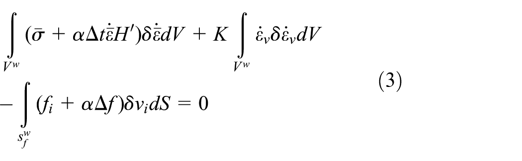
where
Table 1 shows the materials of 6061 aluminum alloy and modulus of elasticity is set to 68,900, Poisson’s ratio is set to 0.3, thermal conductivity is set to 180, and specific heat capacity is 2.4.
Material parameters of workpiece.

Heat transfer
The article simulates the thermal effects within the cutting process, including heat transfer between objects and the environment, and heat generation due to deformation or phase transformation that applicably turn into heat transfer. The mechanisms of heat transfer can be grouped into three broad categories. (1) Conduction: heat transfer through a solid material by contact of one molecule to the next. Heat flows from higher temperature area to lower temperature one. (2) Convection: a heat transfer process involving motion in a fluid (such as air) caused by the difference in density of the fluid and the action of gravity. (3) Radiation: the transfer of heat in the form of electromagnetic waves from one separate surface to another. The energy radiated is transmitted, absorbed, reflected, or a combination of all three cases. We consider a weak thermal–mechanical coupling in this study. In machining process, thermal phenomena (heating, friction at the interfaces) have a real influence on the material behavior during cutting. But the lack of knowledge on phenomena at contact interfaces and coupling mechanisms imposes to use this hypothesis in first approximation. So, in the developed simulations, the temperature evolution is only obtained by considering the dissipation due to mechanical process (heat dissipation). Moreover, the thermal transfer with the ambient air is not considered (adiabatic hypothesis). Finally, the heat equation takes the following form

where β is the Taylor–Quinney coefficient corresponding to heat fraction dissipated by deformation process,
Displacement
Displacement accumulates the micro-displacement of each node since the last re-meshing. For elastic objects, a displacement may be specified for interference fits. The elastic recover age of the object will cause the appropriate stress to be developed.
Wear model
Currently, the DEFORMTM-3D system is based on Archard’s model and Usui’s model, in addition to standard user support. Typically, Archard’s model is widely used for forming applications, and Usui’s model is used for machining applications to compute the insert wearness. Archard’s model can be used with either isothermal or non-isothermal runs. By contrast, Usui’s model can be used only with non-isothermal runs because it requires interface temperature calculations. For both of two models, the die (or insert, in machining) should be meshed with appropriate boundary conditions and inter-object relations defined. This study will examine the complete problem that setup by emphasizing the tool wear part of the data and assuming that the user is familiar with the setup procedures of a typical problem. The formula of the Archard wear model is as follows (equation (5))

where ZAB is the wear, p is the interface pressure, v is the sliding velocity, H is the hardness of the tool material, dt is the time increment, and a = 1, b = 1, c = 2, K = 0.000002 are experimentally calibrated coefficients.
Friction
The friction coefficient specifies the friction at the interface between two objects. The friction coefficient may be specified as a constant, a function of time, or a function of interface pressure. The friction types allowed is shear friction. Constant shear friction is used mostly for bulk-forming simulations. The frictional force in the constant shear model is as follows (equation (6)) 13

where fs is the frictional stress, k is the shear yield stress, and m is the friction factor. This states that the friction is a function of the yield stress of the deforming body.
For contact between two plastic and porous objects, the frictional stress is calculated using the flow stress of the slave object. The lubricant used on the tooling plays a large role in the amount of friction that exists between the tooling and workpiece. The friction in turn affects the metal flow at contact surfaces. Typical values (using constant shear only): (0.08–0.1) for cold-forming processes, (0.2) for warm-forming processes, (0.2–0.3) for lubricated hot-forming processes, and (0.7–0.9) for unlubricated surfaces.
Object type
The object type defines how deformation is modeled for each individual object in a DEFORM problem. Rigid objects are modeled as non-deformable materials. In the deformation analysis, the object geometry is represented by a geometric profile (DIEGEO). Deformation solution data available for rigid objects include object stroke, load, and velocity. The geometric profile is used for all deformation analysis and the mesh for the rigid object is used for all thermal, transformation, and diffusion calculations. When used for the modeling of tooling, the rigid definition increases simulation speed (over elastic tooling) by reducing the number of deformable objects, and hence the number of equations will be solved. There is a negligible loss of accuracy for typical simulations except in cases where tool deflection is significant. Stress and deflection data for the dies are not available during deformation. These data can be obtained at selected single steps by performing a single step die stress analysis.
Simulation and parameter setting
Table 2 illustrated the same cutting parameters of 6061 aluminum alloy in simulation for the three different geometric chip breakers. Depth of cut is set to 2 mm, feed of cut is set to 0.1 mm/s, and major cutting edge angle is set to 5°. Figure 2(a) and (b) shows the simulation diagram for 6061 aluminum alloy chip breaker turning cutting before forming and after forming. The material model of the tool material is tungsten carbide (WC). The tool geometry included clearance angle of 10°, the edge radius is set to 2 mm, and the rake angle is set to 15°.
Cutting parameters of 6061 aluminum alloy of different chip breakers.


Scheme of the 6061 aluminum alloy (a) before cutting and (b) after cutting with chip breaker.
Figure 3 shows the entity diagram of chip breaker for cutting 6061 aluminum alloy (a) without chip breaker, (b) squared chip breaker, and (c) elliptical chip breaker. The material model of the tool material is WC, the tool is integrally formed and heat treated in surface conditions.

Entity diagram of the different chip breakers: (a) without chip breaker (b) squared chip breaker, and (c) elliptical chip breaker.
Figure 4 shows the simulation diagram of chip breaker for cutting 6061 aluminum alloy (a) without chip breaker, (b) squared chip breaker, and (c) elliptical chip breaker.

Simulation diagram of the different chip breakers: (a) without chip breaker (b) squared chip breaker, and (c) elliptical chip breaker.
Results and discussion
Figure 5 shows the simulated effective stress figure for the three different chip breakers in the workpiece. The maximum stress is 841 MPa occurred at 0.012 s for an elliptical chip breaker. The squared chip breaker has the smallest value of 790 MPa. After 0.03 s, there is no obvious difference among the three types.

Effective stress of different chip breakers.
Figure 6 shows the effective stress diagram of the cutting tool without chip breaker in the workpiece. It can be seen that the maximum effective stress generated at tool tip and billet contact.
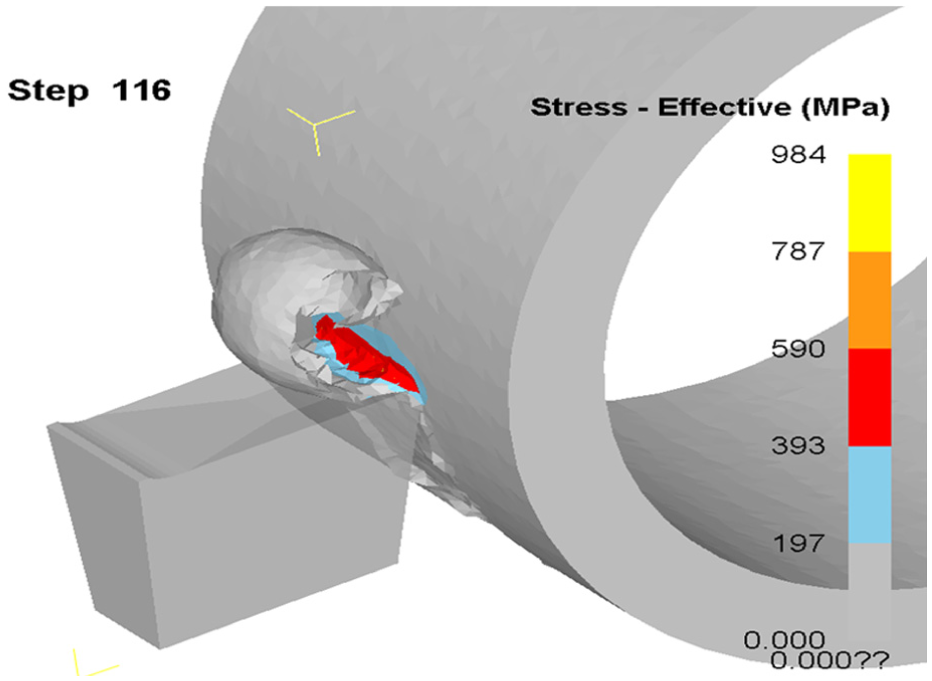
Effective stress of the tool without chip breaker.
Figure 7 shows the effective stress of the cutting tool with squared chip breaker in the workpiece, and the chip was forming conductively along with the turning flow. Figure 8 shows the effective stress of the cutting tool with elliptical chip breaker in the workpiece, its chips seems to be piece by piece around the workpiece. This cutting phenomenon will not easily guide flowing chip, it may be curled up around the workpiece.

Effective stress of squared chip breaker.

Effective stress of elliptical chip breaker.
Figure 9 shows the effective strain diagram of the cutting tool with different chip breakers in the workpiece. The tool without chip breaker produced the greatest strain 16 at 0.2 s. The tool with squared chip breakers produced the smallest effective strain at 7.5 s. The tool with elliptical chip breakers produced the largest effective strain at 0.4 s.

Different chip breakers’ effective strain diagram.
Figure 10 shows the effective strain diagram for tool without chip breaker in the workpiece. Figure 11 shows the effective strain diagram for tool with squared chip breaker in the workpiece. Figure 12 shows the effective strain for tool with elliptical chip breaker in the workpiece. From Figures 10–12, it can be seen that the maximum effective strain was generated in the chip curler.

Effective strain without chip breaker.

Effective strain of squared chip breaker.

Effective strain of elliptical chip breaker.
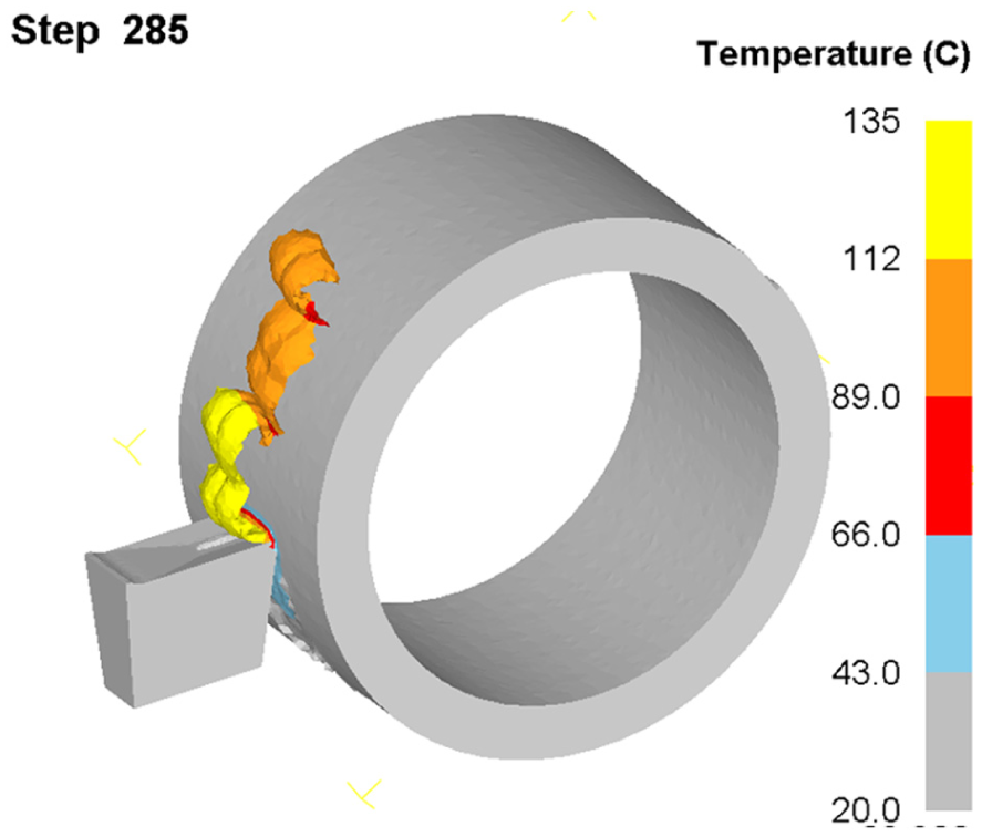
Figure 13 shows the temperature diagram of the tools with different chip breakers in the workpiece; the tool with squared chip breaker produced maximum value at 0–0.5 s, and the temperature is 141°C. Figure 14 shows the temperature diagram of the tool without chip breaker in the workpiece. Figure 15 shows the temperature diagram of the tool with squared chip breaker in the workpiece. Figure 16 shows the temperature diagram of the tool with elliptical chip breaker in the workpiece. From Figures 14–16, it can be seen that the maximum temperature generated in cutting with the three kinds of cutters after separation.

The temperature of different chip breakers.
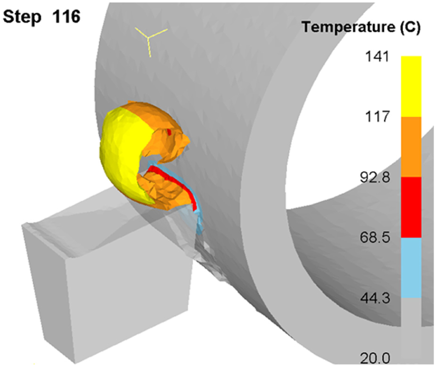
The temperature of tool without chip breaker.

Temperature of tool with squared chip breaker.
Temperature of elliptical chip breaker.
Figure 17 shows the temperature of turning tool without chip breaker in the cutting tool and there is a uniformity of temperature in the cutting tip. Figure 18 shows the temperature of turning tool with squared chip breaker in the cutting tool. It can be seen that the maximum temperature occurs at the top sides of the cutting tool tip. During the cutting process, attention should be paid to the overheating on tip that would cause rupture. Figure 19 shows the temperature of turning tool with elliptical chip breaker in the cutting tool. It can be seen that the maximum temperature occurs at both sides of the cutting tip.

The temperature of turning tool without chip breaker in the cutting tool.

The temperature of turning tool with squared chip breaker in the cutting tool.

The temperature of turning tool with elliptical chip breaker in the cutting tool.
Figure 20 shows the wear simulation diagram of different chip breakers: (a) the wear is homogeneous at the tip for tool without chip breakers, (b) tool with squared type chip breaker generated the maximum wear in the chip breaker area, and (c) tool with elliptic chip breaker induced homogeneous wear at the tip area.

Wear simulation diagram of different chip breakers: (a) without chip breaker, (b) squared chip breaker, and (c) elliptical chip breaker.
Conclusion
In the view of the aluminum alloy 6061 materials, we built a FE model to describe cutting process for cutting tools without chip breaker design, with squared chip breaker design and elliptical chip breaker design, respectively. The results have shown that (1) the maximum stress is 841 MPa occurred at 0.012 s for an elliptical chip breaker, the tool with squared chip breakers has the smallest arising stress value of 790 MPa; (2) the maximum effective strain caused the chip curler; (3) the maximum temperature generated in cutting with the three kinds of cutters after separation; and (4) the squared type chip breaker generated the maximum wear at the chip breaker area, and the elliptic chip breaker induced homogeneous wear at the tip area.
Footnotes
Academic Editor: Mark J Jackson
Declaration of conflicting interests
The author(s) declared no potential conflicts of interest with respect to the research, authorship, and/or publication of this article.
Funding
The author(s) received no financial support for the research, authorship, and/or publication of this article.