
Abstract
The technology of ultra-precision machining with single crystal diamond tool produces advanced components with a higher dimensional accuracy and a better surface quality. This article develops a three-dimensional surface topography simulation model for ultra-precision raster milling process by considering the effect of cutting parameters, tool geometry and tool interference as well as the tool–workpiece relative movement on surface generation. Based on the developed surface topography simulation model, a prediction model for the surface roughness in ultra-precision raster milling is built. The effects of depth of cut and surface topography on the cutting-induced heat generation in ultra-precision milling of aluminum alloy 6061 are investigated. Experiment is conducted to verify the developed surface topography simulation model by raster milling of aluminum alloy 6061 under different feed rates and depths of cut. The experimental results show that the surface topography simulation model can properly simulate the surface profile in the raster milling process and the predicted surface roughness agrees well with the measured results of the machined workpiece. Heat generation in horizontal cutting is less than that in vertical cutting and a larger depth of cut generates more heat on the machined workpiece. The cutting-induced heat generates precipitate on the machined aluminum alloy 6061 which results in a worse surface finish in ultra-precision raster milling.
Introduction
The surface finish of a machined part is one of the most important product quality, which is affected by the tool geometry, the workpiece material, the cutting conditions and other factors such as tool wear. Surface topography literally means the study or detailed description of the surface feature or a region which is crucial to mechanical design and manufacturing by affecting the suitability of a surface for specific functional applications, such as friction, wear and fatigue. 1 Characterization of surface topography has become increasingly important in many engineering fields. The reasons include that a three-dimensional (3D) surface analysis gets information on one more spatial dimension than a two-dimensional (2D) profile and the use of a 3D surface topography assessment provides a deeper insight into the nature of the surface generation mechanism. 2 Therefore, the relationship between the machining process adopted and the achieved surface topography need to be determined. Some research work has been done to develop geometrical models for the prediction of surface topography in turning, 3 ball-end milling, 4 peripheral milling5,6 and high-speed machining. 7
In conventional machining, the achievable machining accuracy is mainly governed by the accuracy of the relative motions between the cutting edge of the cutting tool and the workpiece. When the depth of cut becomes finer, the influence of work material properties on the micro cutting mechanism can be decisive. 8 In ultra-precision machining, the depth of cut is usually less than the average grain size of a polycrystalline aggregate and the variation in the work material properties makes great influence on the surface generation mechanism which usually is ignored in conventional machining. Hence, ultra-precision machining presents problems which are not encountered in conventional machining. Most advances in ultra-precision machining have been gained through precision machine design, laser metrology and an advanced computer control system. Despite these successes, the mechanisms of chip formation and surface generation in ultra-precision machining are still far from being understood. Recently, researches have been found to build the 3D topography model for ultra-precision turned surface which is represented as the combined effect of tool geometry, feed, depth of cut, material properties and machining system dynamics.9–11
Ultra-precision raster milling (UPRM) with a single crystal diamond (SCD) tool is an emerging ultra-precision manufacturing technology, which can directly produce freeform surfaces with sub-micrometer form accuracy and nanometric surface finish. Due to the different cutting mechanics, the surface generation is very dependent on cutting strategies and more factors affect the surface quality in UPRM, as compared with ultra-precision diamond turning and conventional milling. Cheng et al. 12 reported that the factors affecting surface roughness in UPRM include cutting parameters, feed direction, step distance and tool geometry (swing distance, tool nose radius). However, their theoretical and experimental studies are conducted based on the 2D profile analyses of scallop height generations. A 2D profile cannot be efficient in characterizing the surface profiles and can indeed display identical roughness parameters, yet contain different mechanical properties. Hence, a 3D surface topography analysis in UPRM is highly needed.
At the same time, the power consumed in the actual metal cutting process is largely converted into heat and the generated heat is dissipated by the employed cutting tool, the generated chip and the machined workpiece. The heat results in high temperature and stress at the chip–tool and workpiece–tool interfaces and therefore affects the material properties of workpiece, machining accuracy and surface finishing as well as tool life. Few researches are found to study the cutting heat generation in ultra-precision machining, since it is believed that the heat generation in ultra-precision machining under a small depth of cut is much less than those in conventional machining. In fact, the cutting-induced heat generation is not negligible in ultra-precision machining. Recent research has shown that the machining error due to the thermal deformations of cutting tool and workpiece in ultra-precision diamond turning was found to reach the order of a few micrometers. 13 The temperature rise on the diamond cutting of oxygen-free high thermal conductivity (OFHC) copper is found that the maximum temperature (nearly 570 °C) was located near the shear plane because the heat conductivity of the OFHC copper and the diamond is more than 10 times as large as those of the workpiece and the tool in conventional machining. 14 Their studies also showed that the decrease in the depth of cut decreases the cutting force and the maximum temperature. Therefore, knowledge of the ways in which the cutting conditions, tool geometry and workpiece materials affect the heat generation is essential for the study of thermal effects on tool life, surface finishing and machining efficiency in ultra-precision machining.
UPRM technology is currently applied in the machining of ductile materials such as aluminum and copper alloys. Aluminum alloy 6061 (al6061), with chemical composition by wt%: Mg 0.92, Si 0.76, Fe 0.28, Cu 0.22, Ti 0.10, Cr 0.07, Zn 0.06, Mn 0.04 and Al balance, is one of the precipitation hardening alloys and contains a favorable combination of medium strength, good machinability and corrosion resistance. The extent of precipitation in al6061 is affected by the chemical composition of the material, the manufacturing technology and the heat treatment. 15 The size, distribution and number of the generated precipitations are affected by the heating temperature, time of annealing and cooling rate. A number of studies have been conducted to predict and control the effect of aging and heat treatment on characterizing precipitate, microstructure and the mechanical properties of this alloy. 16 This infers that under different cutting conditions, the generated precipitates on the machined al6061 are different.
In this article, a 3D surface topography simulation model is established to simulate the surface finish profile by studying the factors affecting surface generation in UPRM. The surface topography simulation model incorporates the effect of cutting parameters, tool geometry and the relative motion between the cutting tool and the workpiece as well as the tool interference on the surface finish profile. This article also studies the effect of surface topography on the cutting-induced heat generation in UPRM. Experiments are designed to verify the surface topography simulation model and the time–temperature–precipitation characteristic of al6061 is employed to experimentally study the effect of cutting-induced heat generation on surface finishing in UPRM.
Surface generation mechanism in UPRM
UPRM is performed on a computerized numerical control (CNC) ultra-precision multi-axis freeform machining system (Freeform 705G from Precitech, USA), as shown in Figure 1. The SCD tool on the spindle makes rotation and linear movement along the X-axis and/or Y-axis, while the workpiece located on the table linearly moves along the Z-axis. In Figure 1, L refers to the swing distance of diamond tool on the spindle and r is the tool nose radius of the cutting tool.
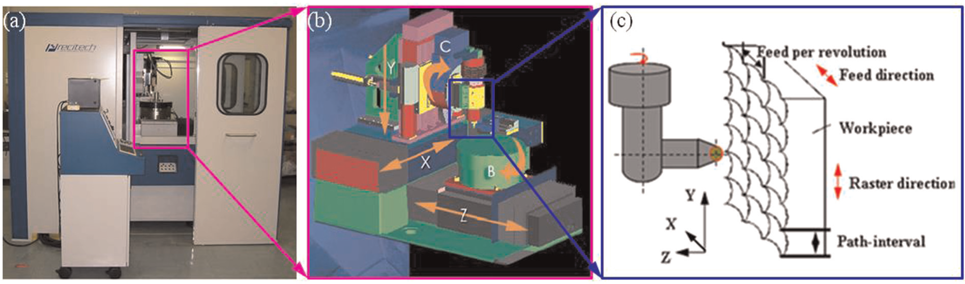
Ultra-precision raster milling in the multi-axis machine system.
During surface machining, diamond tool generally feeds parallel to the X- or Y-axis, which leads to two possible cutting strategies in UPRM: horizontal cutting and vertical cutting. In horizontal cutting, feed direction is parallel to the X-axis and the raster direction is along the Y-axis, while the Z-axis is employed to control contour for achieving the desired surface profile (Figure 2). Vertical cutting is done by changing the functions of the Y-axis and the X-axis. The theoretical surface roughness in UPRM includes two parts: the scallop height in X-axis direction (tool edge cut scallop height, hxth) and the scallop height in Y-axis direction (tool nose cut scallop height, hyth). In horizontal cutting, the tool edge cut scallop height (hx) is also called as the feed-interval scallop height (hf) which is determined by the feeding length per revolution (f) and the swing distance of diamond tool (L):
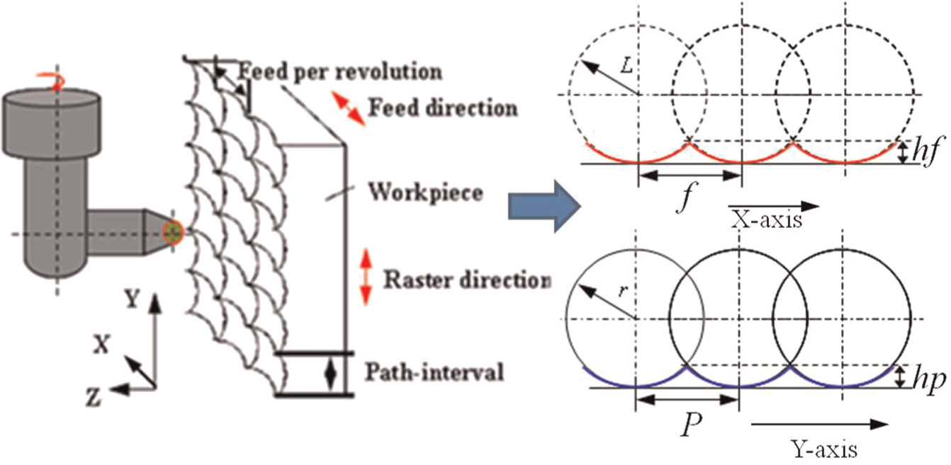
Surface scallop height generation in horizontal cutting.
Modeling of surface topography
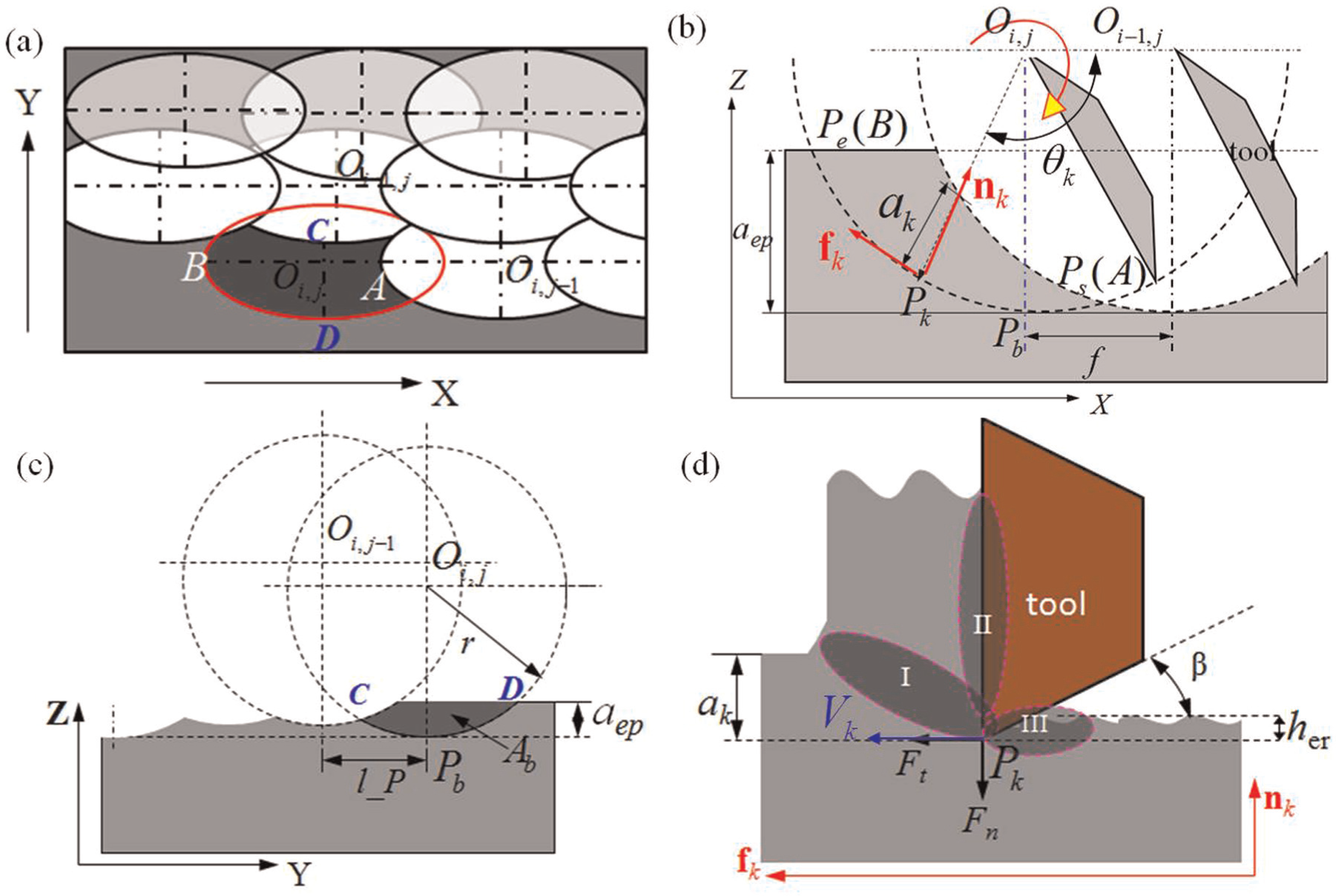
The material is removed in UPRM by the discontinuous contact between the SCD tool and the workpiece. The discontinuous contact between cutting tool and workpiece generates different surface topography pattern on the machined surface under different cutting conditions (Figure 3). It indicates that the surface topography in UPRM is not only affected by the feed length per revolution (f) and the step size (P) but also determined by the shift length (Δf). The shift length is 0 in Figure 3(a)–(c), while the shift lengths in Figure 3(d)–(f) are not equal to 0.
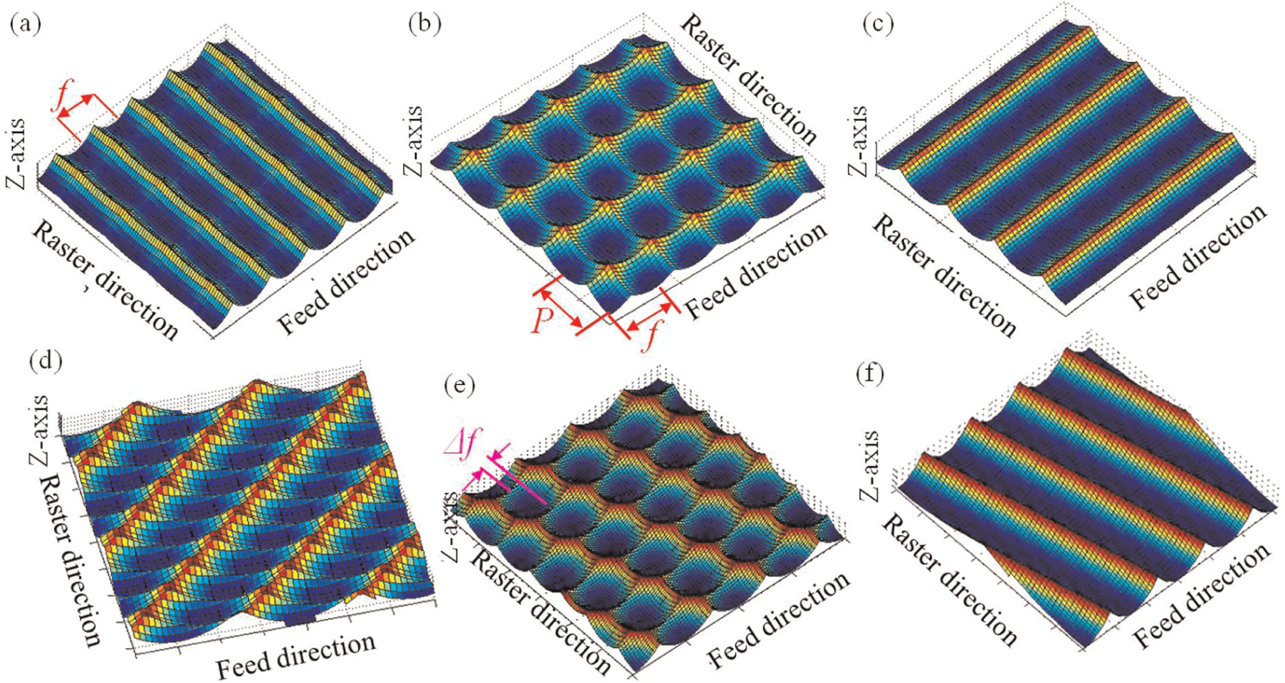
Surface topographies under different cutting conditions: (a)
In this study, the shift length (Δf) refers to the distance of two start positions between two adjacent steps where the diamond tool starts removing materials from workpiece, as shown in Figure 3(e). It depends on the cutting parameters and the geometries of the machined workpiece as well as the tool path generation (TPG). When planning tool paths in the actual machining, different values of feed rate (the rapid feed FR and the cutting feed rate FC) are defined to improve machining efficiency, as shown in Figure 4. It infers that acceleration, deceleration and uniform velocity are generated in the machining process due to the different values of feed rates (Figure 4(b)). In Figure 4(a), LW is the length of the machined workpiece, aep is the depth of cut, h refers to the clearance height and le and lr refer to the entry and retreat lengths, respectively.
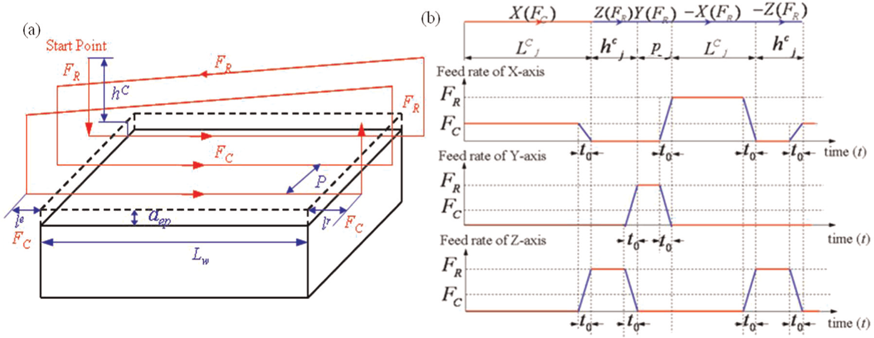
(a) Tool path planning and (b) feed rate variations in UPRM.
For Precitech Freeform 705G, the standard program acceleration and deceleration time (tad) is 10 ms, which infers that any slide or rotary axis will accelerate or decelerate to its next position within 10 ms. The shift length (Δf) is therefore affected by the cutting parameters, TPG and the standard program acceleration and deceleration time (tad). In this study, the ratio of shift length (Δf) to the feeding length per revolution (f) is defined as the shift ratio (η)
where the MOD function returns the remainder after a number is divided by a divisor.
According to equation (1), the generated surface topography in UPRM relies on the cutting parameters (S, FR, FC, aep), the acceleration and deceleration time of machine (tad), TPG (P, le, lr, h) as well as the geometries of the machined workpiece (LW). The maximum peak-to-valley height (Rt) of the machined surface is represented as follows
where R1 refers to the swing distance (L) and R2 refers to the tool nose radius (r) in horizontal cutting; while in vertical cutting, R1 refers to the tool nose radius (r) and R2 refers to the swing distance (L).
From equation (2), when the shift ratio is 0, the surface topography depends on the cutting parameters and tool geometry (Figure 3(a)–(c)), the maximum peak-to-valley height (Rt) of the machined surface in UPRM can be simplified as
Effect of tool interference on surface generation in the feed direction.
Effect of surface topography on surface finish
As discussed before, under the same feed per revolution (f) and path interval (P), different shift lengths generate different surface topographies and therefore affect the surface roughness in UPRM. In fact, the surface topography not only affects the material removal volume per revolution (material removal rate (MRR)) but also influences the contact area (
Factors affecting heat generation in UPRM: (a) surface topography pattern, (b) the tool–workpiece contact time, (c) tool–workpiece contact area and (d) deformation zones.
In metal cutting, the power consumed is largely converted into heat and the generated heat is dissipated by cutting tool, chip and workpiece materials. During the material removal process, heat is generated in three deformation zones: the primary, secondary and tertiary deformation zones, as shown in Figure 6(d). Heat generated in the primary deformation zone (Region I) is due to the plastic work done at the shear plane, while the heat generated in the secondary deformation zone (Region II) is owing to the work done in deforming the chip and overcoming the sliding friction at the tool–chip interface zone. The heat generated in the tertiary deformation (Region III) is due to the work done to overcome friction which occurs at the rubbing contact between the tool clearance face and the newly machined surface. Therefore, heat generation in the primary and secondary zones is highly dependent on the cutting conditions and material properties, while heat generation in the tertiary zone is mostly affected by the clearance angle (β) of diamond tool and the elastic recovery height (her) of the workpiece material properties. 17
The temperature rise on the tool rake face in the machining is due to the combined effect of the heat generated in the primary and secondary deformation zones. For the temperature rise on the machined workpiece, the main heat source is the primary and tertiary deformation zone (Regions I and III in Figure 6(d)), while the effect of heat generated in Region II is relatively less significant.
18
With reference to the work done by Palanisamy et al.,
19
the rate of energy consumption in metal cutting can be given by
From the above analyses, the cutting-induced heat generation on the machined workpiece in UPRM is affected by cutting parameters (cutting feed rate, spindle speed, depth of cut, step size), workpiece material properties and the generated surface topography. The total heat generated on the workpiece in one revolution increases with the increase in the depth of cut (aep) and step size (P), owing to the increase in the cutting force, the tool–workpiece contact area and the contact time, which agrees well with the conclusions provided in the previous studies. 20 Meanwhile, the surface topography also affects the heat generation by changing the contact area and the contact time as well as the cutting force between the workpiece and the cutting tool.
Experimental verification
Experiment design
Cutting experiments are conducted to study the effect of surface topography on surface finishing in horizontal cutting and vertical cutting. The machined samples are plane surfaces and the size of the machined workpiece is
Cutting parameters and tool geometries for surface machining.
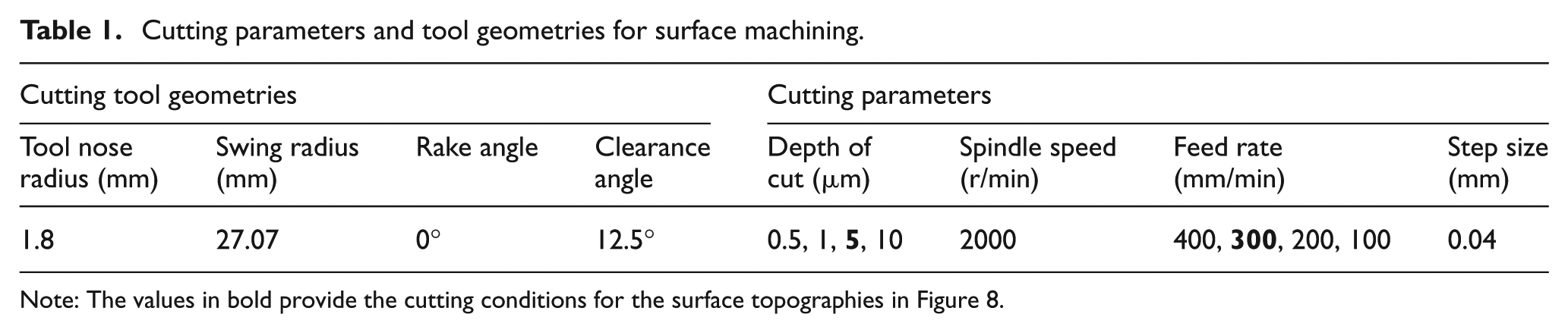
Note: The values in bold provide the cutting conditions for the surface topographies in Figure 8.
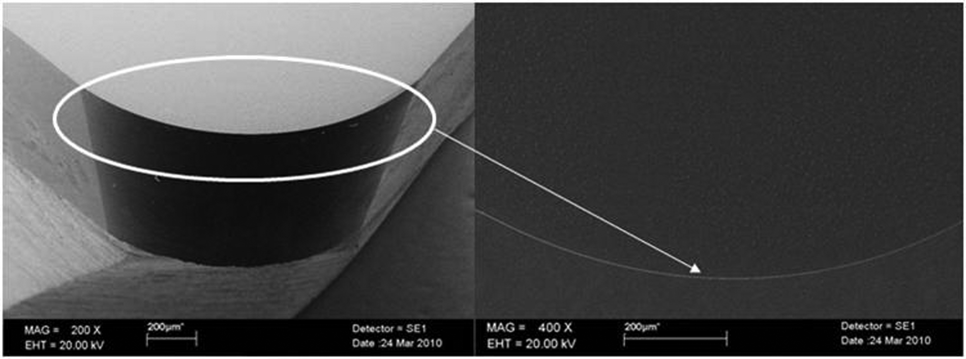
SEM images of single crystal diamond tool used in the experiment.
Experimental results
After the cutting experiments, all the specimens are examined immediately by using SEM (JEOL Model JSM-6490) and energy-dispersive X-ray (EDX) spectroscopy analysis is used to determine the composition of the generated particles. An optical profile system (Wyko NT 8000) is also used to measure surface roughness for the machined al6061 samples. The Wyko NT8000 is an optical profiler available for the non-contact measurement of step heights, roughness and surface topography of microelectromechanical systems (MEMS), metal materials, semiconductors, medical devices, precision lenses and more. Figures 8–10 show the measured surface topographies of the machined samples under different cutting conditions.
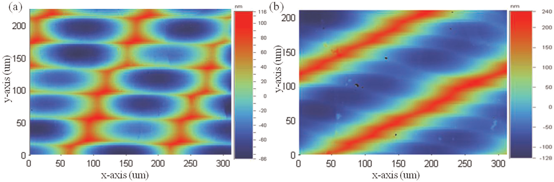
The measured surface topographies of the ultra-precision raster milled al6061 in (a) horizontal cutting and (b) vertical cutting (FC = 300 mm/min; aep = 5 µm).
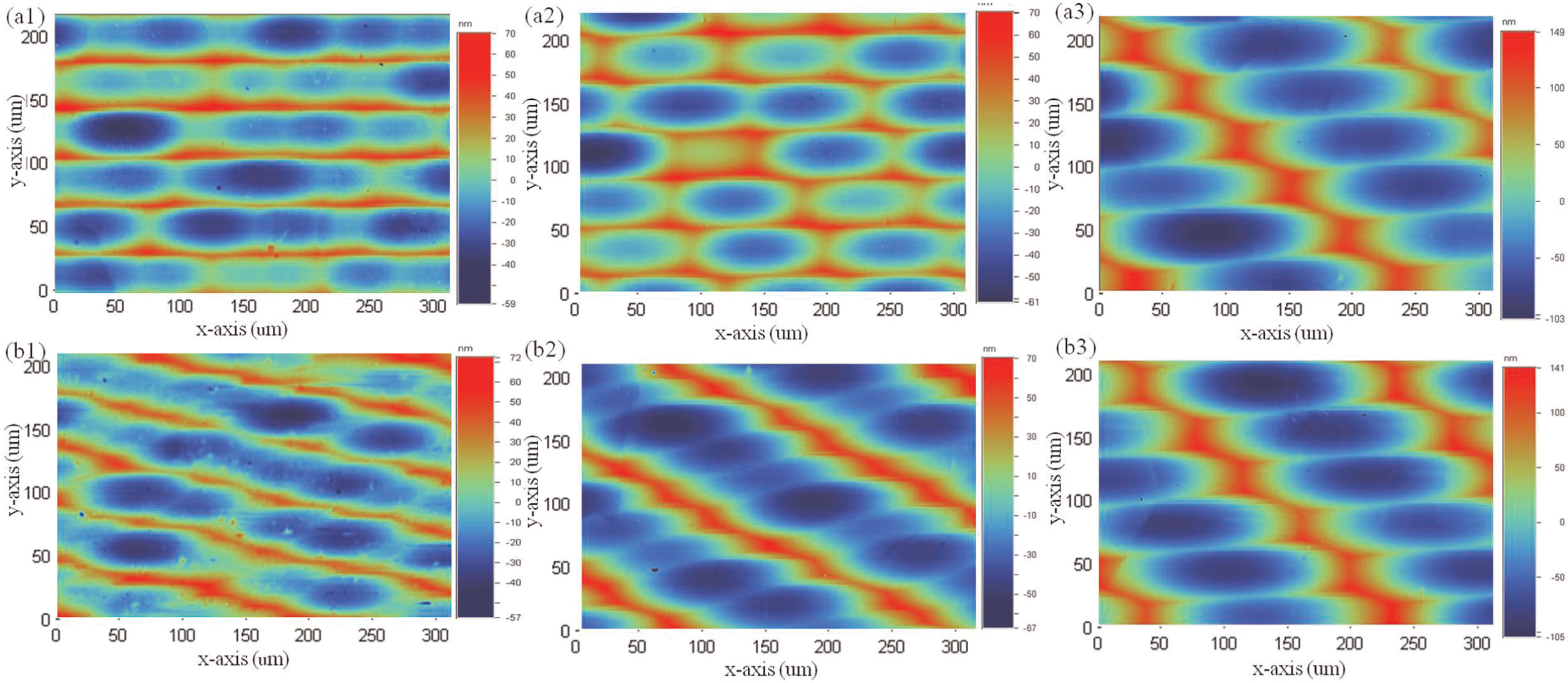
The measured surface topographies of the ultra-precision raster milled al6061 in (a1)–(a3) horizontal cutting and (b1)–(b3) vertical cutting when feed rate is changed as 100, 200 and 400 mm/min (aep = 5 µm).
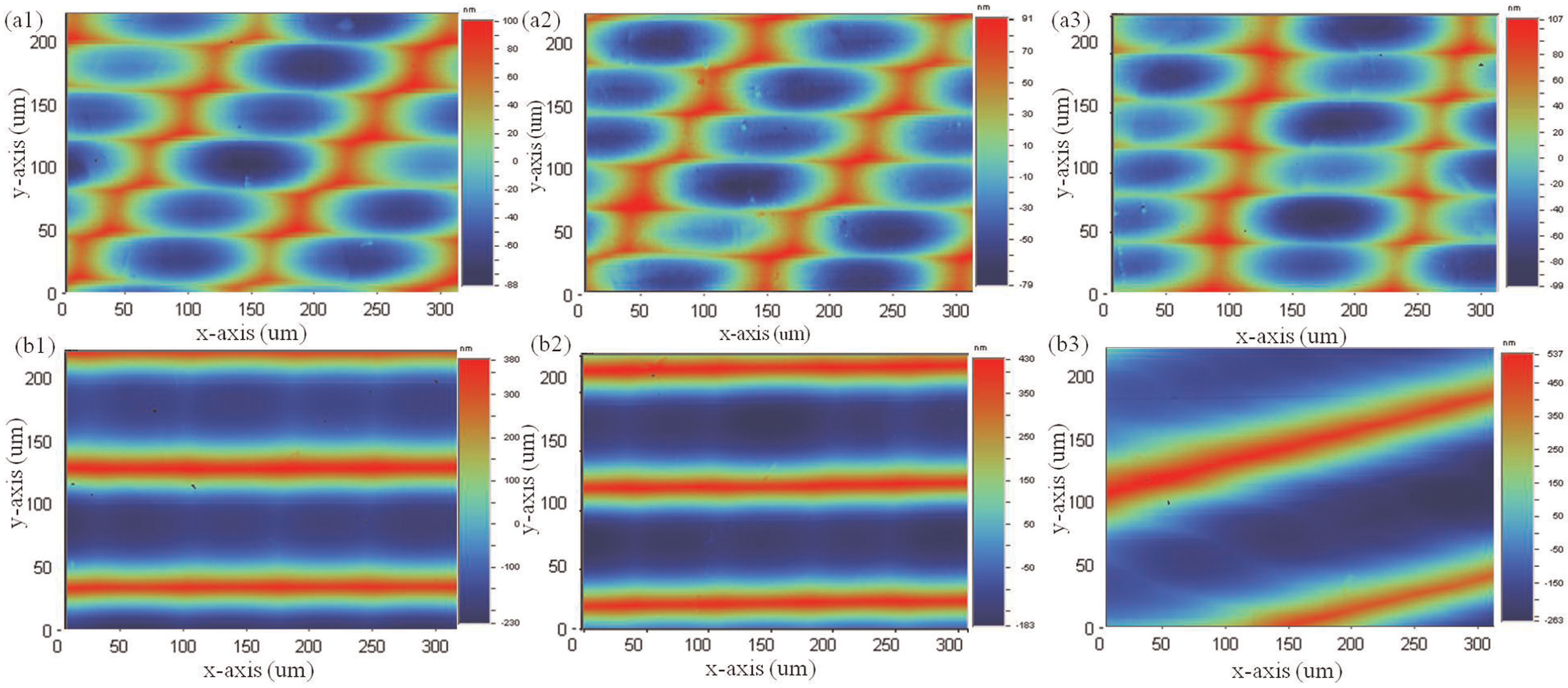
The measured surface topographies of the ultra-precision raster milled al6061 in (a1)–(a3) horizontal cutting and (b1)–(b3) vertical cutting when depth of cut is changed as 0.5, 1 and 10 µm (FC = 300 mm/min).
Discussion and analyses
Verification of surface topography simulation model
Figure 11 shows the effect of feed rate on the arithmetic average roughness (Ra) of the machined surface in horizontal cutting and vertical cutting. From Figure 11, the decrease in feed rate decreases the surface roughness (Ra) in horizontal cutting by generating lower feed-interval scallop height. However, different results are found in vertical cutting: as the cutting feed rate increases from 100 to 300 mm/min, the surface roughness (Ra) increases; as the cutting feed rate increases from 300 to 400 mm/min, the surface roughness decreases. Figure 12 compares the tool nose cut profiles in vertical cutting under feed rates 300 and 400 mm/min. It shows that the surface height under feed rate 400 mm/min is lower than that under feed rate 300 mm/min. The reason is that the presence of tool interference in vertical cutting decreases the tool nose cut scallop heights and therefore decreases the surface roughness in the ultra-precision raster milled surface. Moreover, when the feed rate decreases from 300 to 100 mm/min, the improvement on surface quality in vertical cutting is about 40 nm (Ra) which is larger than that in horizontal cutting of about 4 nm (Ra).
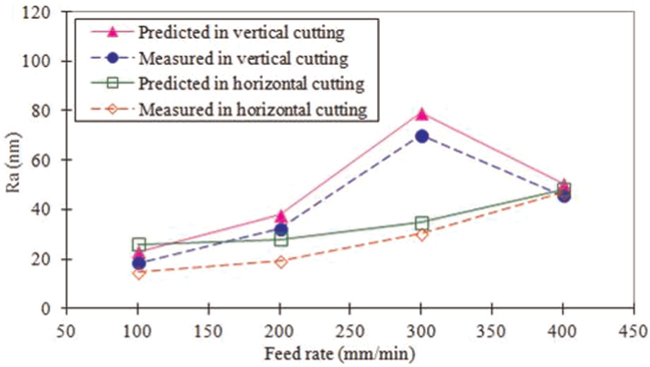
Comparison between the predicted and the measured surface roughness (Ra, the arithmetic roughness) in horizontal cutting and vertical cutting under different feed rates.
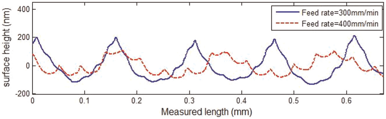
The measured tool nose cut profiles in vertical cutting under different feed rates.
Figure 13 shows the simulated surface topographies in horizontal cutting and vertical cutting when the cutting feed rate and the depth of cut are set to 300 mm/min and 0.005 mm, respectively. When compared with the measured surface topographies shown in Figure 8, the surface topographies obtained from the proposed simulation model are very similar to those measured from the machined workpiece. At the same time, the predicted surface roughness by the prediction model is close to the measured one (Figure 11). This indicates that the developed models for simulation and prediction are applicable in UPRM.
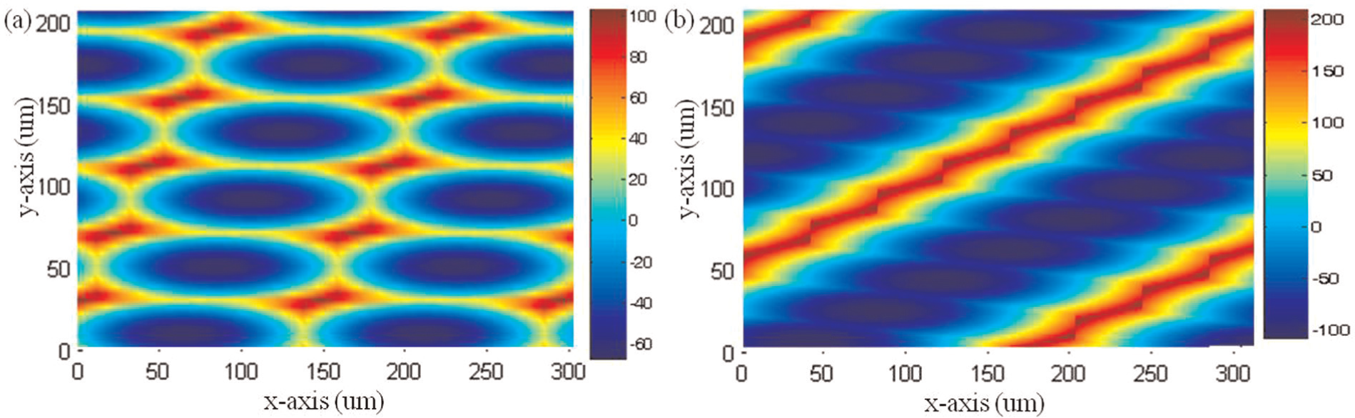
The simulated surface topographies of the ultra-precision raster milled al6061 in (a) horizontal cutting and (b) vertical cutting (FC = 300 mm/min; aep = 0.005 mm).
In Figure 11, there is deviation between the measured results and the predicted ones in horizontal cutting and vertical cutting. Especially, the deviation between the measured result and the predicted one in horizontal cutting increases with the decrease in feed rate. One reason is that the proposed model ignores the materials’ effect on surface generation in UPRM. Another reason is that a larger feed rate results in a higher surface roughness and therefore the materials’ effect becomes relatively insignificant. Accordingly, when the cutting feed rate is equal to 400 mm/min, the predicted surface roughness is pretty close to the measured one in horizontal cutting and vertical cutting. Meanwhile, the measured surface qualities are better than the predicted ones when the cutting feed rate is smaller than 400 mm/min. The reason is that the presence of the material elastic recovery decreases the tool nose scallop height. 21
Effect of depth of cut on surface finish
From the above analyses, the change in feed rate affects the surface topography and the scallop heights of the raster milled surface, and therefore influences the achieved surface roughness. According to the theoretical analyses in UPRM (Figure 2), the depth of cut makes no effect on the generation of scallop heights in the feed and raster directions. However, referring to the 3D surface topographies in Figure 3, the depth of cut (aep) affects the shift length (Δf), and therefore influences the surface topography as well as the maximum peak-to-valley height (Rt) of the machined surface in UPRM. Figure 14 presents the effect of the depth of cut on the arithmetic average roughness (Ra) in horizontal cutting and vertical cutting. It can be seen that, under the same cutting conditions, the achieved surface quality in horizontal cutting is better than that in vertical cutting. According to the equations for calculating the feed-interval and path-interval scallop heights, under the same cutting conditions, the feed-interval scallop height in vertical cutting is larger than that in horizontal cutting.
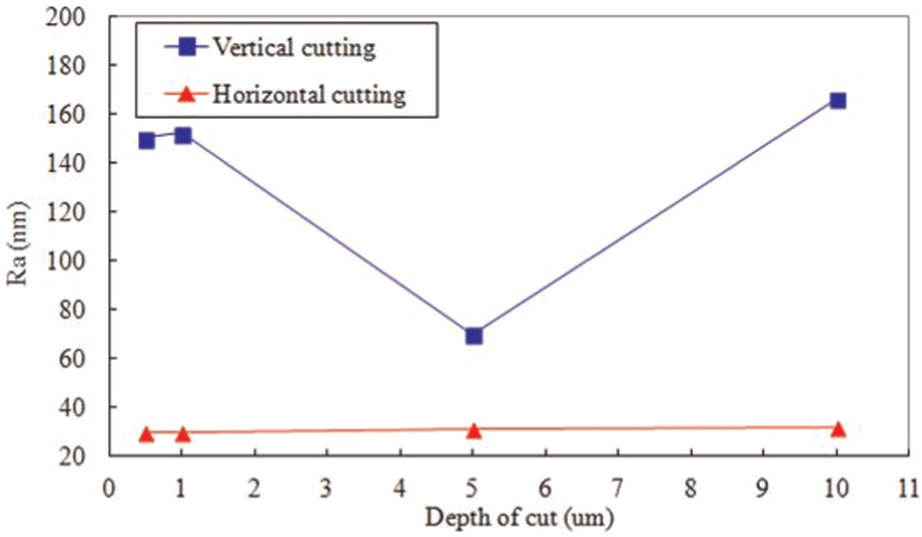
Effect of depth of cut on the arithmetic roughness (Ra) in horizontal and vertical cuttings.
The depth of cut makes larger effect on surface roughness in vertical cutting than that in horizontal cutting. Moreover, as the depth of cut is equal to 0.5 µm, the best surface finishing in horizontal cutting is achieved; however, the best surface quality in vertical cutting is achieved when the depth of cut is equal to 5 µm. The reasons are that the change in depth of cut makes larger influence on the surface topographies in vertical cutting and the presence of tool interference decreases the surface roughness, as shown in Figures 8(b) and 10(a1). This infers that the depth of cut affects the kinematic surface roughness in UPRM by changing the generated surface topographies and the surface quality can be improved by optimizing surface topography. Especially, under the same cutting conditions, the optimal surface topography for achieving the best surface finish is different for horizontal cutting and vertical cutting.
From Figure 10, when the depth of cut is changed from 0.5 to 1 µm, the surface topographies are similarly to each other. However, the surface roughness of these samples in Figure 14 is different: the increase in depth of cut increases the surface roughness in horizontal cutting and vertical cutting. As the depth of cut is changed from 0.5 to 1 µm, the surface roughness increases about 2.2 nm (Ra) in horizontal cutting and about 6 nm (Ra) in vertical cutting. The reason is that the increase in depth of cut increases the cutting force and the tool–workpiece contact area, and therefore increases the cutting-induced heat on the machined surface. The SEM images in Figure 15 show that the larger precipitates start coarsening and get bigger and bigger while the relatively smaller ones become lesser and lesser. This indicates that the larger the depth of cut, the more heat generated during raster milling process.
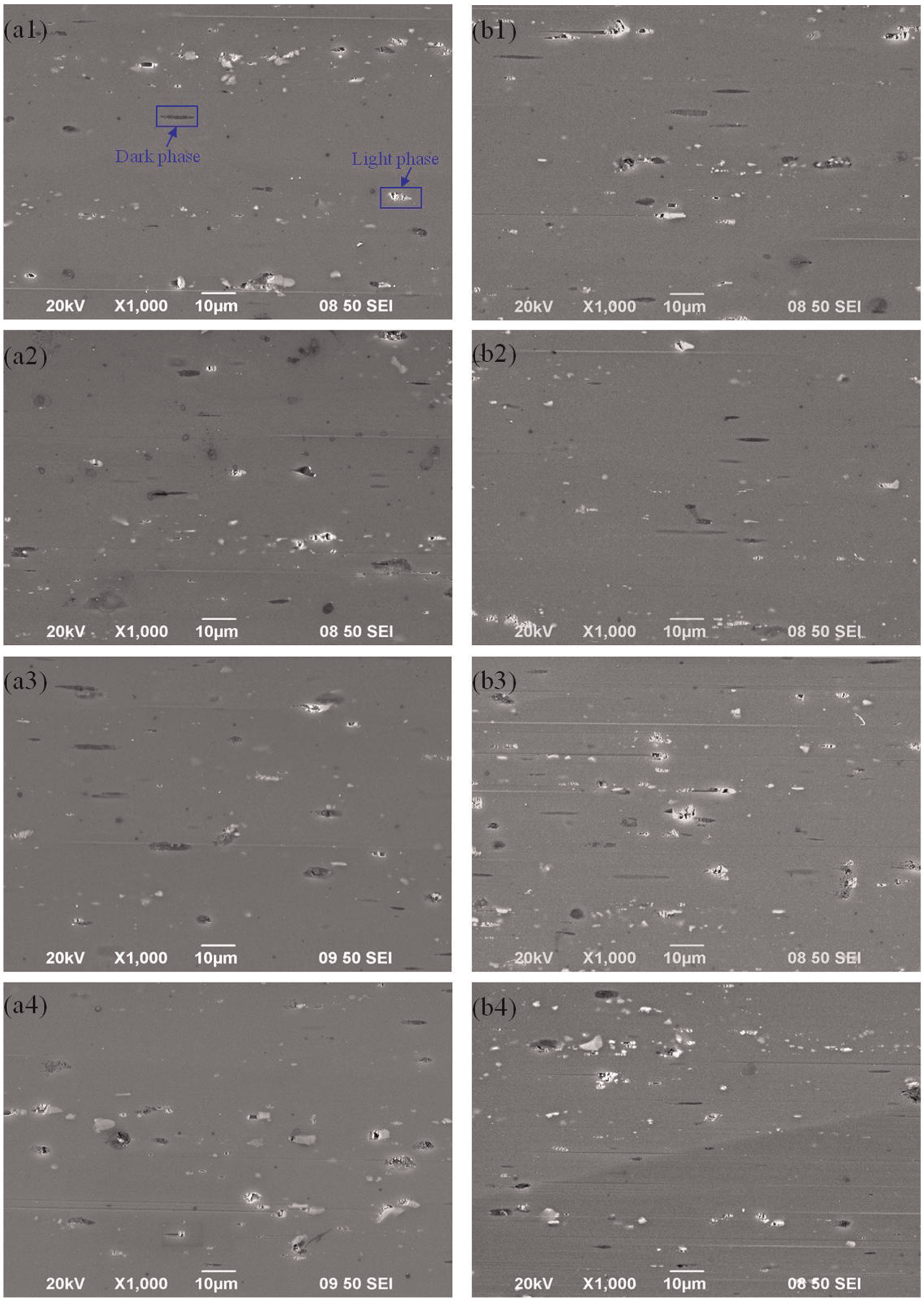
The SEM images for the ultra-precision raster milled al6061 in (a1)–(a4) horizontal cutting and (b1)–(b4) vertical cutting when depth of cut is changed as 0.5, 1, 5 and 10 µm.
There are two types of precipitates in the machined surfaces of al6061: the darker and the lighter phases. The darker phases are identified as Al, Mg2Si and Si atoms, while the light ones are identified as Fe, Si and Al atoms. 22 The two types of precipitates are relatively hard and brittle as compared with the workpiece material. 23 During raster milling process, when the diamond tool encounters a hard particle during machining, the hard particle is sheared and fractured. The sheared portion of the particle is dragged along by the diamond tool and generates scratch marks on the ultra-precision raster milled surface, which results in imperfection on the machine and affects the surface quality. From Figure 15, the increase in depth of cut generates longer scratch marks because of a longer contact time between the cutting edge and the workpiece.
Under the same cutting conditions, the generated surface topographies are different in vertical cutting and horizontal cutting. It can be seen that the material removal volume per revolution in vertical cutting is larger than that in horizontal cutting when the depth of cut is equal to 10 µm (see Figure 10(a3) and (b3)). Figure 15(a4) and (b4) shows that the number of the white precipitates in vertical cutting is more than that in horizontal cutting and more scratch marks are generated in vertical cutting when compared with that in horizontal cutting. The higher the MRR, the more heat generated on the raster milled of al6061.
Conclusion
This article studies the factors affecting surface topography in UPRM and develops a 3D surface topography simulation model. The influence of cutting parameters, tool geometry and tool interference on surface generation and cutting-induced heat generation in ultra-precision milling process is investigated. Experiments are conducted to verify the built surface topography simulation model and study the effect of surface topography on heat generation by UPRM of al6061. The major findings in this article are summarized as follows:
The surface topographies obtained from the simulation model are very similar to those measured from the machined workpiece.
The predicted surface roughness meets well with the experimental result. The difference between the measured and the predicted results is due to the appearance of material recovery and the precipitates on the machined al6061.
The presence of elastic recovery produces a better surface finish by generating a lighter tool nose cut scallop height.
The presence of tool interference improves the surface quality by decreasing the feed-interval scallop heights.
The change in depth of cut affects the surface roughness by generating different surface topographies and the surface topography can be optimized to improve surface quality.
A larger depth of cut generates more heat on the machined surface due to the increase in cutting force and tool–workpiece contact area in UPRM.
More heat is generated in vertical cutting than that in horizontal cutting under the same cutting conditions because the surface topography affects the heat generation in UPRM.
The precipitate generated by the cutting-induced heat in the machining of al6061 generates imperfection on the machined surface, which results in a worse surface finish.
This study provides an important means for better understanding the mechanisms of surface generation and chip formation as well as the tool wear in ultra-precision milling. This contributes to avoiding the need to conduct expensive and time-consuming trial cutting tests to ensure the product quality, and therefore makes the ultra-precision milling process more predictable and more efficient.
Footnotes
Declaration of conflicting interests
The authors declare that there is no conflict of interest.
Funding
The authors would like to express their sincere thanks to the support of National Natural Science Foundation of China (No. 51205067) and the Research Fund for the Doctoral Program of Higher Education of China (No. 20124420120003). The authors would also like to thank the support by Guangdong Innovative Research Team Program (No. 201001G0104781202).