
Abstract
The upper limb exoskeleton rehabilitation robot can realize the partial functional compensation of upper limb and complete the various types of rehabilitation training for each joint of upper limb. However, the existing upper limb exoskeleton rehabilitation robots are lack of flexible reconfigurability, which are difficult to meet the diversified patient objects and rehabilitation needs, and have some problems, such as insufficient motion compliance, poor portability, and wearing comfort. To effectively solve the above problems and improve the effect of upper limb rehabilitation training, this project plans to carry out the following research: Firstly, analyze the structural characteristic and movement mechanism of upper limb, clarify the configuration theory of the modular flexible upper limb exoskeleton rehabilitation robot with reconfigurable, and design and optimize the mechanism form and structural parameters of the reconfigurable modular flexible upper limb exoskeleton rehabilitation robot. Secondly, based on the perspective of rigid–flexible coupling integration of bone–muscle–robot, the integrated equivalent mechanism model is constructed and the integrated dynamics model is established to plan compliance motion and develop intelligent compliance control strategy. Finally, the simulation experimental platform is built for simulation experimental demonstration of upper limb rehabilitation training. The implementation of this study will provide new idea and method for realizing the effect of flexible, compliance, light, and comfortable of upper limb rehabilitation training.
Keywords
Introduction
The upper limb exoskeleton rehabilitation robot organically integrates robotics, ergonomics, informatics, cybernetics, medicine, and other disciplines. 1 –3 It can effectively replace the artificial assisted rehabilitation, realize the partial functional compensation for upper limb, and complete various types of rehabilitation training for each joint of the upper limb. It has become the research hot spot in the robot field. 4 –8
However, in practical application, the upper limb scale parameters and rehabilitation stages of different patients are different. Due to the relatively fixed structure of the existing upper limb exoskeleton rehabilitation robot, it cannot well adapt to the diverse patient objects and rehabilitation needs. In addition, most of the existing upper limb exoskeleton rehabilitation robots are the motor-driven rigid structures, although some upper limb exoskeleton rehabilitation robots also adopt flexible driving and transmission modes such as pneumatic muscle and rope traction, most of the components direct contact with the upper limb are still rigid, the rigid components have advantages in operation accuracy and bearing capacity, but they have problems such as insufficient motion flexibility, poor portability, and wearing comfort, and the wearing deviation may cause secondary injury to the patient’s upper limbs. In view of these problems, in recent years, some researchers began to study the flexible upper limb exoskeleton rehabilitation robot with flexible contact components instead of rigid contact components. 9 However, the research on the flexible upper limb exoskeleton rehabilitation robot is still in its infancy, and there are some urgent problems to be solved, such as insufficient output stiffness, failure to form a systematic and rigorous configuration optimization design principle, and lack of in-depth research on intelligent compliance control mechanism.
Completing reasonable configuration design is the primary task to realize the expected functions of the upper limb rehabilitation robot. At present, the upper limb rehabilitation robot can be divided into end-effector type and exoskeleton type according to the configuration classification, and the rigid series structure is mainly used. The world’s first upper limb rehabilitation robot is MIT-MANUS, 10 which belongs to the end-effector type upper limb rehabilitation robot. It is a series rigid five link mechanism, which can assist the patient’s shoulder and elbow joint in the horizontal plane for rehabilitation training. Compared with the end-effector type upper limb rehabilitation robot, the exoskeleton type upper limb rehabilitation robot can realize partial functional compensation for the upper limb, help patients to take care of themselves, and complete more types of rehabilitation training for each joint of upper limb. In recent years, the exoskeleton type upper limb rehabilitation robot has become the research hot spot in the field of upper limb rehabilitation robot. The ARMin series of upper limb exoskeleton rehabilitation robot developed by the ETH Zurich have good inheritance. At present, there are many improved versions, 11 and its functions have been continuously improved. It has multiple active and passive degrees of freedom and can realize the auxiliary functions of upper limb movement with more functions. However, the ARMin upper limb exoskeleton rehabilitation robot still has defects to be overcome, the use of ARMin robot-assisted therapy requires the rehabilitation specialist to determine the support parameters before training. If the rehabilitation specialist wants to modify the support parameters during the treatment, the training must be stopped, restart the robot after setting the new support parameters, and whether its adaptive adjustment ability is reliable is also worth further study. Trigili et al. 12 developed a four-degree of freedom upper limb exoskeleton rehabilitation robot NESM for shoulder and elbow rehabilitation training by designing a self-aligning mechanism for passive rotating joints, the rotation axis of the rehabilitation robot can be smoothly self-aligned with the rotation axis of the patient. To realize that the actuating stiffness of the target joint can be adjusted according to the specific injury degree of the patient’s upper limb and meet the needs of family rehabilitation training, Liu et al. 13 designed a new portable upper limb exoskeleton rehabilitation robot, which has five passive degrees of freedom and can independently adjust the joint stiffness by moving the pivot position, however, the robot can only carry out rehabilitation training for the elbow joint and cannot carry out multi-joint collaborative rehabilitation training.
To improve the motion compliance and wearing comfort, the upper limb exoskeleton rehabilitation robot with flexible driving mechanism and flexible transmission mechanism came into being. At present, the flexible driving mechanism and flexible transmission mechanism mainly include pneumatic muscle and rope pulling mechanism. 14 –16 Mao et al. 17 proposed a rope driven upper limb exoskeleton rehabilitation robot for nerve rehabilitation by using the rope driven parallel mechanism instead of the rigid link open chain mechanism, which has the advantages of lightweight and does not limit the natural degree of freedom of the human upper limb. Zhang et al. 18 developed an upper limb exoskeleton rehabilitation robot named RUPERT using the driving mode of artificial pneumatic muscle, which can better simulate the motion characteristics of the upper limb, and its motion performance is more in line with the characteristics of the upper limb. In addition, the flexible upper limb exoskeleton rehabilitation robot with flexible contact components has emerged in recent years. Lessard et al. 9 designed a coat-type flexible exoskeleton CRUX based on the flexible chloroprene rubber material, which can not only reduce the weight of the exoskeleton and improve the portability but also improve the wearing comfort, and can meet the needs of upper limb rehabilitation training in the home environment.
In addition, the establishment of the comprehensive dynamics model is of great significance to the intelligent compliance control for the upper limb exoskeleton rehabilitation robot. 19,20 However, the existing research on the dynamics modeling of the upper limb exoskeleton rehabilitation robot is mainly focused on the rehabilitation robot’s mechanical structure. 19 ,21 In practical application, the rehabilitation robot and the patient’s upper limb move together. They interact and jointly affect the rehabilitation effect. The author’s previous research found that the parallel recursive dynamics modeling method is an effective way to establish the comprehensive dynamics model of flexible robot, 22 which laid a good foundation for the dynamics modeling problem from the perspective of human–robot integration.
Moreover, ensuring the good motion compliance of the upper limb rehabilitation robot is the important prerequisite for achieving good rehabilitation effect. In addition to innovating the structural design, the rehabilitation motion compliance can also be improved by improving the motion planning and control methods. 23 –27 Goto et al. 28 took a redundant driven upper limb exoskeleton rehabilitation robot as the research object, starting from the aspects of mechanical structure and control methods, the feasibility of realizing the compliant motion of the physical prototype of the rehabilitation robot is verified by simulation and experiment. Islam et al. 29 proposed the fractional order sliding mode control algorithm to control the seven-degree of freedom upper limb exoskeleton rehabilitation robot (u-Rob) and verified the algorithm’s good tracking and anti-buffeting effect by using Lyapunov theory, which improved the motion flexibility, however, they did not fully consider the fit characteristics between the robot and patient, and the wearing comfort needs to be further improved, and the product is still in the simulation stage, whether it has good rehabilitation effect in practical application needs to be further verified. To realize the compliance control for the upper limb exoskeleton rehabilitation robot, Brahmi et al. 30 proposed an adaptive compliance tracking controller based on the improved function approximation technology, designed and planned the desired trajectory based on the prediction of the human motion intention, and adopted the damped least square method to reduce the deviation between the actual position of the robot and the human motion intention and improve the motion compliance, but the human–robot cooperation ability needs to be further improved by optimizing the control gain.
To improve the safety and effectiveness of upper limb wrist rehabilitation training, Xu et al. 31 proposed an interactive compliance control scheme for wrist rehabilitation device. The control system is composed of a low-level tracking loop and a high-level admittance loop, this interactive compliance control method can self-adapt to adjust the range of training motion and encourage patients to actively participate. In addition, the author’s previous research found that fuzzy system, shaping controller, and fast terminal fuzzy sliding mode control method are the powerful tools for building complex robot intelligent control system, 32,33 which is the useful exploration for the realization of intelligent control method in this study.
To sum up, although many explorations have been made in the field of upper limb exoskeleton rehabilitation robot in recent years, and positive achievements have been achieved, there are still deficiencies. In summary: the existing upper limb exoskeleton rehabilitation robots do not have flexible reconfigurability, cannot well adapt to the diverse patient objects and rehabilitation needs, and do not fully consider the fitting characteristics between rehabilitation robot and human upper limb, and the flexible components generally have the problems such as poor output stiffness and support, and lack of the effective basis for configuration optimization design; lack of dynamics modeling research from the perspective of human–robot integration; compliance movement planning lacks clear decomposition procedures and optimization processes, and the research on how to ensure the smooth compliance of rehabilitation movement with external interference is not perfect.
Therefore, the rest of this article is organized as follows. In the second section, the configuration of reconfigurable modular flexible upper limb exoskeleton rehabilitation robot is designed. In the third section, the rigid–flexible coupling integrated dynamics model of skeleton–muscle–robot is studied. In the fourth section, the intelligent fast terminal fuzzy sliding mode compliance control system is presented. In the fifth section, the results of the simulation experiment are analyzed. The sixth section draws the final conclusions and future works.
Configuration
Analysis of the physiological structure characteristics of human upper limb
The muscle group drives the overall movement of upper limb, and the muscle group is in parallel and redundant configuration. When analyzing the motion function mapping from the human upper limb to the upper limb exoskeleton rehabilitation robot, this study regards the muscle as flexible driving component, the skeleton as rigid support component, and the joint as flexible joint component, which cooperate to complete the upper limb movement, as shown in Figure 1. It is generally believed that in addition to the palm, there are seven main rigid degrees of freedom of the human upper limb, including three shoulder joints, one elbow joint, and the rest three wrist joints, as shown in Figure 2.

The functional mapping of human upper limb tissues.

The distribution of main rigid degrees of freedom of human upper limb.
In fact, due to the flexibility of human tissue, the joints cannot be regarded as simple kinematic pairs and their combinations. In addition to the seven main rigid degrees of freedom mentioned above, human upper limb also have other flexible degrees of freedom with small variation range. Most of the existing studies simplified the degrees of freedom of human upper limb, and it is easy to design and control, but it does not accord with the actual characteristics of upper limb, which led to the unsatisfactory wearing comfort, motion flexibility, and feedback accuracy. In addition, the scale parameters, rehabilitation stage, and rehabilitation need of patients are different in reality. The existing upper limb exoskeleton rehabilitation robots generally do not have reconfigurability and cannot well adapt to the diversified patient objects and rehabilitation need, which is the urgent problem to be solved.
Preliminary design of structure form
Firstly, the driving form is determined according to the motion mechanism of the human upper limb and the motion law of skeletons, tendons, muscles, ligaments, and other tissue structures during movement. The corresponding muscle-like flexible components are designed and arranged in the upper limb exoskeleton rehabilitation robot. The muscle-like flexible components are used to achieve flexible degrees of freedom, increase passive degrees of freedom, and fit the human upper limb as much as possible.
Specifically, the overall structure diagram of the reconfigurable modular flexible upper limb exoskeleton rehabilitation robot is shown in Figure 3: It mainly consists of handrail, flexible joint of wrist, flexible joint of elbow, flexible joint of shoulder, fixing device of shoulder, pneumatic flexible module, pneumatic flexible module branch chain, quick-change connector, flexible strap of front arm and rear arm, flexible sensing device, and airway interface. The pneumatic flexible modules are connected in series by the quick-change connectors to form the pneumatic flexible module branch chains. The flexible joint of wrist and flexible joint of elbow, flexible joint of elbow and flexible joint of shoulder are respectively connected by the three pneumatic flexible module branches distributed in parallel, and the pneumatic flexible module branches distributed in parallel can increase the support stiffness. The reconfigurable modular flexible upper limb exoskeleton rehabilitation robot assists the upper limb movement mainly through the deformation drive of pneumatic flexible modules and flexible joints and realizes various rehabilitation training of upper limb by using the deformation combination of various pneumatic flexible modules and flexible joints, such as torsion, elongation, contraction, bending, and spiral. The flexible joint fully considers the micro-slip characteristics of each joint center of the upper limb in the movement process, which can adapt to the joint motion. The reconfigurable modular flexible upper limb exoskeleton rehabilitation robot designed in this study has both good support and flexible deformation and takes into account safety, comfort, and flexibility. In addition, according to the actual use requirements, the numbers and types of pneumatic flexible modules and flexible joints required for assembly can be combined, and the flexible upper limb exoskeleton rehabilitation robots with various configurations can be flexibly reconstructed to adapt to more application scenarios, objects, and requirements.

The overall structure diagram of the reconfigurable modular flexible upper limb exoskeleton rehabilitation robot.
The composition diagram of pneumatic flexible module is shown in Figure 4, which is mainly composed of fiber reinforced structure, cavity structure, airway grid, flexible contact layer, and suction cup silica gel module.
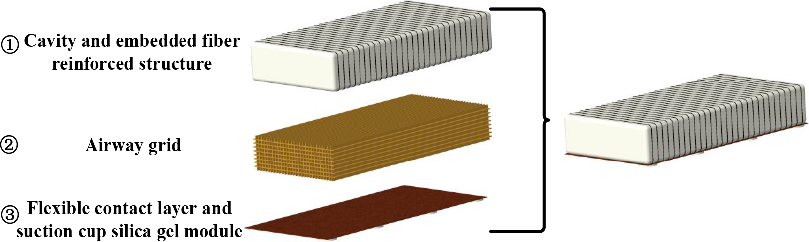
The composition diagram of pneumatic flexible module.
The fiber reinforced structure is mainly used to limit the deformation in the nonfunctional direction, so as to improve the deformation efficiency. The fiber is embedded in the flexible cavity wall and can be flexibly arranged through single or multiple groups of different winding methods. Different arrangement methods can realize different degrees of torsion, elongation, contraction, bending, spiral, and other deformation. Specifically, when a single group of fiber filament is wound in one direction, the pneumatic flexible module can realize torsion or elongation deformation, when the winding rise angle is equal to or close to 0° (Figure 5(a)), the pneumatic flexible module can realize axial elongation deformation when inflated and expanded, when the winding rise angle is not equal to 0° (Figure 5(b)), the pneumatic flexible module can realize axial torsion deformation and elongation deformation to a certain extent, with the increase of winding rise angle, the torsional deformation increases and the elongation deformation decreases, when the winding rise angle increases to a certain value, the torsional deformation decreases, when the winding rise angle is close to 90°, the pneumatic flexible module does not produce torsional deformation, which is mainly reflected in axial shrinkage deformation. Two groups of fiber filaments wound in opposite directions can obtain pure axial elongation or shrinkage deformation (Figure 5(c)). In addition, when the above two arrangement methods are reinforced by a single bundle of fiber filament through asymmetric single side or spiral form, the bending or spiral deformation of the pneumatic flexible module can be realized (Figure 5(d) and 5(e)). Figure 5 shows several typical fiber filaments with different arrangements.
The airway grid can effectively improve the stiffness of robot and provide greater output force during auxiliary rehabilitation training, to drive the patients with great muscle tension. The airway grids of several typical section shapes are shown in Figure 6.
The silica gel modules with suction cup are arranged around the bottom of pneumatic flexible module, through controlling the pressure in the suction cup, the silica gel module can be adsorbed on the human body surface, and the patient can flexibly adjust the pressure within the set safe negative pressure threshold. In addition, to reduce the undesired slip between the robot and the upper limb, the “anchor points” are set at the parts where the upper limb are rigid and suitable for stress, and then the force transmission paths are designed with flexible materials to transmit the driving force of the driver to the “anchor points,” so as to realize flexible binding and transmit the auxiliary force at the same time.

The schematic diagram of different winding modes of pneumatic flexible module fibers: (a) The winding rise angle is equal to or close to 0°, (b) The winding rise angle is not equal to 0°, (c) Two groups of fiber filaments wound in opposite directions, (d) Reinforced by a single bundle of fiber filament through asymmetric single side, and (e) Reinforced by a single bundle of fiber filament through asymmetric spiral form.

The airway grids of several typical cross-sectional shapes: (a) triangular section, (b) rectangular section, and (c) hexagonal section.
The flexible joint is composed of McKibben pneumatic artificial muscle, hyperelastic strain sensor, global measurement unit, and flexible body. The pneumatic artificial muscle and hyperelastic strain sensor are embedded in the flexible body. Each flexible joint is designed with 16 pneumatic artificial muscles, which are arranged on the flexible body according to the distribution form of 4 × 4, each pneumatic artificial muscle is equipped with a hyperelastic strain sensor. The hyperelastic strain sensor is used to measure local deformation, the microcontroller is used to control four hyperelastic strain sensors as a module, and the modular control is used to make the pneumatic artificial muscles work together and realize a variety of deformation of flexible joints. The overall deformation and driving force generated can independently adapt to the upper limb size, form, and motion ability of different wearers and provide sufficient assistance for upper limb rehabilitation. The global measurement unit can measure the overall deformation, acceleration, and angular velocity of flexible joints in the three-dimensional global coordinate system, which is used to control the motion of upper limb joints. The flexible body can be made of highly compressible and stretchable silicon flexible body, which is easy to wear and can well fit the complex three-dimensional contour of upper limb. The structural form and modularization function of flexible joint are easy to realize deformation and reconfiguration.
The flexible joints are fixed at the wrist, elbow, and shoulder joints respectively. Taking the wrist flexible joint as an example, Figure 7 shows the deformation diagram of flexible joint.

The deformation diagram of flexible joint: (a) original form, (b) shrinkage deformation, (c) bending deformation, and (d) bending torsion deformation.
Based on the configuration characteristics of the reconfigurable modular flexible upper limb exoskeleton robot designed in this study, different numbers and forms of pneumatic flexible modules and flexible joints can be combined according to different application objects and rehabilitation needs to flexibly reconstruct the flexible upper limb exoskeleton rehabilitation robot in practical application. For example, you can only exercise any single joint such as wrist joint, elbow joint, and shoulder joint, or any two or three joints, or only exercise forearm and rear arm, or a combination of any joint and front and rear arms. The quick-change connectors are designed between pneumatic flexible modules and between flexible joints and pneumatic flexible modules to facilitate flexible assembly and combination.
In addition, the three pneumatic flexible module branches of the front and rear arms are distributed in parallel, and the front and rear arms are connected in series. Therefore, the reconfigurable modular flexible upper limb exoskeleton robot designed in this study combines the advantages of large workspace, efficient and flexible operation of series mechanism, and high pose accuracy, good support stiffness and operational stability of parallel mechanism. The authors conducted in-depth research and practical application of series robot and parallel robot. 22,33–37
Skeleton–muscle–robot rigid–flexible coupling integrated dynamics model
The reconfigurable modular flexible upper limb exoskeleton rehabilitation robot fits closely with the human upper limb, and they together form the rigid–flexible coupling integrated system of skeleton–muscle–robot. To construct the rigid–flexible coupling integrated dynamics model of skeleton–muscle–robot, it is necessary to establish the human–robot integrated equivalent model including skeleton, muscle, and robot.
The schematic diagram of skeleton–muscle–robot rigid–flexible coupling integrated equivalent model is shown in Figure 8, including multiple rigid–flexible integrated equivalent models: forearm pneumatic flexible module branch–human forearm equivalent muscle model–human ulna equivalent link, forearm pneumatic flexible module branch–human forearm equivalent muscle model–human radius equivalent link, rear arm pneumatic flexible module branch–human rear arm equivalent muscle model–human humerus equivalent link, robot flexible wrist joint–human wrist joint equivalent muscle model–human equivalent wrist joint model, robot flexible elbow joint–human elbow joint equivalent muscle model–human equivalent elbow joint model, robot flexible shoulder joint–human shoulder joint equivalent muscle model–human equivalent shoulder joint model, and so on.
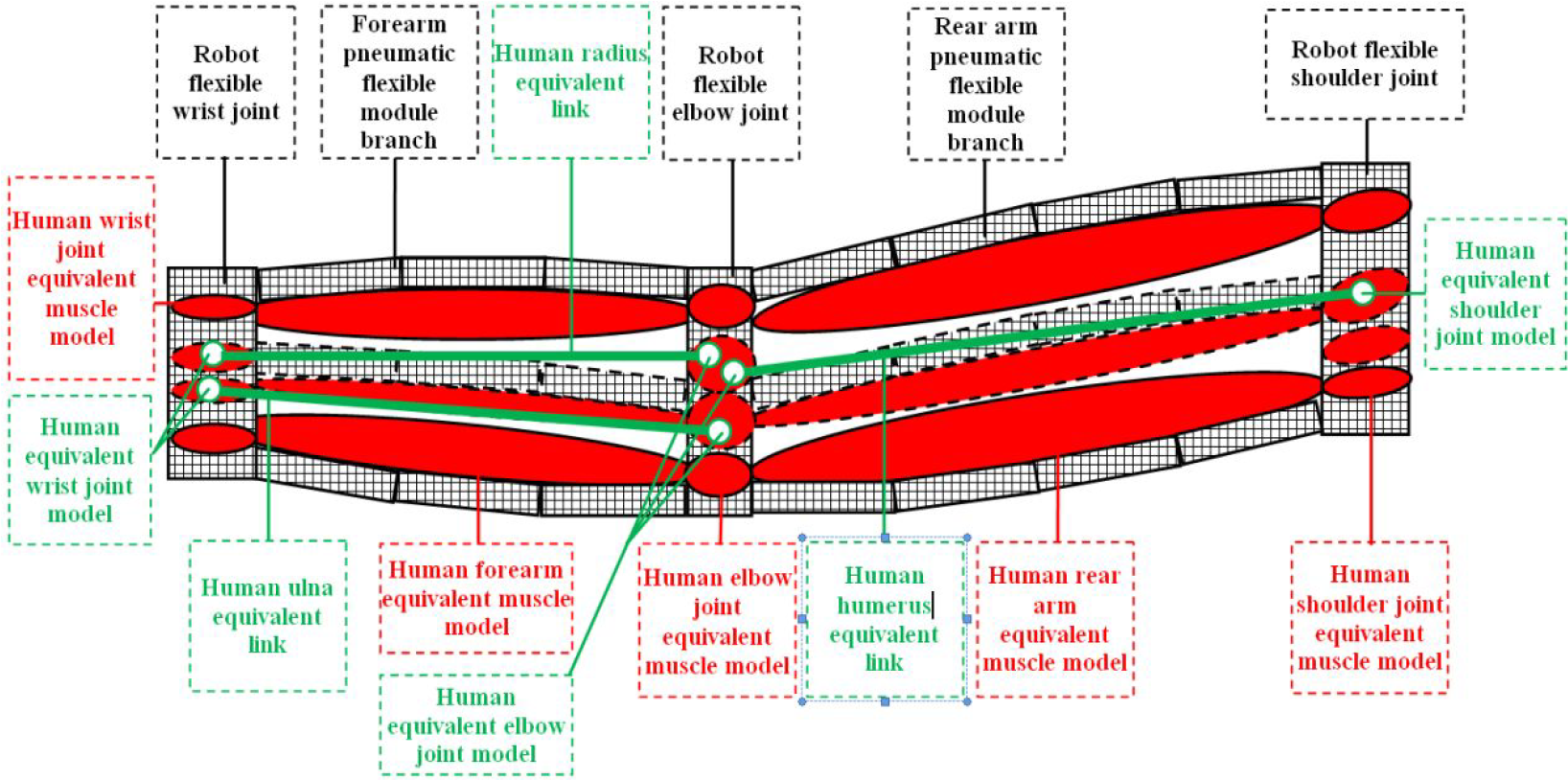
The skeleton–muscle–robot rigid–flexible coupling integrated equivalent model.
The equivalent models are organically assembled together by using the constraints of common position to form the complete rigid–flexible coupling integrated equivalent model of skeleton–muscle–robot. In this model, skeleton and joint are rigid structures, muscle, pneumatic flexible module branch chain, and flexible joint are flexible structures, and rigid structures and flexible structures are coupled with each other, assisting upper limb to complete rehabilitation training.
Considering the large deformation characteristics of pneumatic flexible module, the dynamics model of pneumatic flexible module is established based on Hamilton equation of motion and Lagrange principle. On this basis, using the parallel recursive dynamics modeling method proposed in our previous research, 22 combined with the virtual joint velocity, constraint force impulse, and regular momentum derivative, the multi-body system dynamics model of the pneumatic flexible module branch chain is established. The pneumatic flexible module branch chain is composed of several pneumatic flexible module units in series, and the virtual joints between the pneumatic flexible modules are set, which can better simulate the flexible connection between pneumatic flexible modules. The combination and decomposition process of pneumatic flexible module branched is shown in Figure 9.

The combination and decomposition process of pneumatic flexible module branched.
The pneumatic flexible module branch chain is connected with each flexible joint, and the connection point mainly meets the following two conditions: The displacement of the pneumatic flexible module branch chain at the connection point corresponds to the displacement of the flexible joint; the force generated by the branch chain of pneumatic flexible module at the connection point is balanced with the force generated by the flexible joint. Equation (1) represents the generalized connected coordinate vector

where
The equivalent models in the rigid–flexible coupling integrated system of skeleton–muscle–robot are connected with each other. The relationship between pneumatic driving force and flexible strap binding force, robot output force, human–robot contact interaction force is studied. Considering the possible relative sliding and relative rotation between the robot and the upper limb contact surface, their interaction mechanism is studied for compensation control. The constraints of muscle tension and binding force between human and robot are introduced, and the following skeleton–muscle–robot rigid–flexible coupling integrated dynamics model is constructed

where


The parallel recursive dynamics modeling method studied has the characteristic of parallel recursive algorithm, which can calculate the generalized coordinates of each component in the rigid–flexible coupling integrated system of skeleton–muscle–robot in parallel and can assemble and combine each component by using constraints at the same time, so it has high algorithm efficiency, the dynamics model can be flexibly transformed according to different configurations of the robot.
Intelligent compliance control
Planning compliant rehabilitation motion
Based on the skeleton–muscle–robot rigid–flexible coupling integrated dynamics model, according to the characteristics of upper limb rehabilitation motion, the rehabilitation motion model is abstracted, and the knowledge base is established based on the optimal dynamic rehabilitation performance evaluation index. When the rehabilitation motion command is issued, the rehabilitation task planning method is provided through the knowledge base to establish the constraint relationship between human upper limb and robot. Applying the knowledge of upper limb rehabilitation motion to optimize and decompose the typical rehabilitation motion that the robot needs to perform, so that the current rehabilitation motion is carried out according to the steps of optimization and decomposition, then expanding the rehabilitation motion, and using the relevant motion planning knowledge to complete the execution of the current rehabilitation task. The process of the typical rehabilitation motion model is shown in Figure 10, which includes the basic steps and related motion sequences of the typical rehabilitation motion.

The process of the typical rehabilitation motion model.
Figure 11 is the rehabilitation motion planning flowchart of the upper limb exoskeleton rehabilitation robot, which uses the sensing equipment to perceive and determine the rehabilitation motion type online and in real time, then calls the motion execution parameters in the knowledge base to generate the motion execution flag matrix, plans the corresponding rehabilitation motion according to the motion execution flag, and optimizes and decomposes the rehabilitation motion, which makes the upper limb exoskeleton rehabilitation robot carry out rehabilitation assistance according to the steps of optimal decomposition.

The rehabilitation motion planning flowchart.
In addition, considering the possible wearing posture deviation such as relative sliding and relative rotation between human–robot bonding surfaces in planning compliant rehabilitation motion, the wearing posture deviation can be expressed as follows

where
The optimal dynamic compliant rehabilitation trajectory is planned in Cartesian coordinate system and joint coordinate system, and the corresponding dynamic compliant motion trajectory planner is designed. The optimal dynamic compliance rehabilitation trajectory planning process is shown in Figure 12.

The optimal dynamic compliance rehabilitation trajectory planning process.
In addition, to further improve the stability and compliance of rehabilitation motion, it is necessary to reduce the robot chattering as much as possible. To design the intelligent fast terminal sliding mode compliance controller by using the fast terminal sliding mode control (FTSMC) algorithm, the optimal dynamic compliance rehabilitation motion trajectory planning method and input shaping vibration suppression technology are applied. First, the ZV input shaper is designed for the first-order natural frequency of the upper limb exoskeleton rehabilitation robot, the ZVD input shaper is designed for its second-order natural frequency, and the EI input shaper is designed for its third-order natural frequency. Then the three single mode input shapers are convoluted to form the three mode ZV-ZVD-EI input shaper. Further, by designing the reasonable fast terminal sliding mode surface, fast terminal sliding mode controller, and corresponding fuzzy system, a fast terminal fuzzy sliding mode compliance control method is proposed, in which the fuzzy system can adaptively adjust the generalized gain term of FTSMC in real time according to the size of sliding mode surface, so as to effectively reduce chattering and improve the flexibility of rehabilitation movement.
Design of shaping controller
The ZV shaping controller of two pulse sequence is expressed as

where Ai
is the amplitude and
In addition, for ZVD shaping controller, the residual vibration is expressed as

where
Supposing that the shaping controller with three pulse sequences is designed, we can obtain the following equation:
For EI shaping controller, the constraint condition can be expressed as

where
When

The pulse time delay ti can be expressed as

If
And the shaping controllers of ZV, ZVD, and EI are built in Simulink (Figure 13).

The shaping controllers: (a) ZV, (b) ZVD, and (c) EI.
Fast terminal fuzzy sliding mode control
The fast terminal sliding surface can be designed as

where
The fast terminal fuzzy sliding mode controller can be designed as

where
The fuzzy set can be defined as


where NB, NM, NS, Z and PS, PM, PB denote negative big, negative medium, negative small, zero and positive small, positive medium and positive big, respectively.
Taking fast terminal sliding surface si as the input, wi is the output, the fuzzy rule can be designed in the following form

where

where
The product inference engine, single-valued fuzzy controller, and center average defuzzizer are used to design the fuzzy system, the output of the fuzzy system can be obtained as follows

where


where M is the number of fuzzy rules, N is the number of fuzzy subsets in the input fuzzy set,
Based on equation (5) and the above fuzzy control system, the fast terminal fuzzy sliding mode controller is expressed as

IFTFSMC system
The intelligent fast terminal fuzzy sliding mode control (IFTFSMC) system of the upper limb exoskeleton rehabilitation robot is shown in Figure 14.

The intelligent fast terminal fuzzy sliding mode compliance control system.
In practice, firstly, the desired driving parameter trajectories are input into the dynamic compliant trajectory planner. Then, in the three-mode ZV-ZVD-EI input shaper, the driving parameters obtained in the dynamic compliance trajectory planner are processed by the convolution method, and then the modified driving parameters are input into the fast terminal fuzzy sliding mode closed-loop system as the motion command, and driving the robot to perform the auxiliary motion of compliance rehabilitation.
Simulation experiment analysis
Taking the geometric center points of wrist joint, elbow joint, shoulder joint, and handrail as the coordinate origins when the robot is not deformed, establishing the local coordinate systems of wrist joint, elbow joint, shoulder joint, and handrail as O1–x1y1z1, O2–x2y2z2, O3–x3y3z3, and O–xyz, which are shown in Figure 15.

The local coordinate systems of wrist joint, elbow joint, shoulder joint, and handrail.
The dynamics model of the robot is accurately built in MATLAB, and the proposed IFTFSMC algorithm and the FTSMC algorithm are coded. Figures 16 to 18 show the position error results of the robot wrist joint, elbow joint, and shoulder joint after applying the control algorithms of IFTFSMC and FTSMC. In the following figures, the red curve represents IFTFSMC, the blue curve represents FTSMC, and the green curve represents the ideal trajectory.

The position error of wrist joint.

The position error of elbow joint.

The position error of shoulder joint.
It can be seen from the results that the position error of wrist joint is greater than that of elbow joint, and the position error of elbow joint is greater than that of shoulder joint. This is mainly because the accumulation of position error from shoulder joint to elbow joint to wrist joint gradually increases.
In addition, the position error of FTSMC is greater than IFTFSMC’s, obviously, this proposed IFTFSMC method has better advantages in controlling robot position error and motion compliance. This is because we combine the advantages of the shaping controller and fuzzy shaping controller and make up for their disadvantages. For the shaping controller, it does not need to change the structure of the robot system, nor does it need complex feedback loops and sensors, but the length of the pulse sequence will cause the time delay of the robot system output, and due to the shaping for the reference input, there will be inevitable control errors between the actual output and the reference input, in addition, the design of the shaping controller depends on the natural frequency and damping ratio of the robot system, so the uncertainty of the robot system parameters will also affect the vibration suppression effect of the shaping controller. To overcome these shortcomings of the shaping controller, this study introduces the fuzzy controller, which has strong robustness and is especially suitable for the control of nonlinear time-varying and time-delay systems.
Moreover, to further study the compliance of the robot, according to the simulation results, the Jerk at the end of the handrail is obtained. It can be seen from Figure 19 that the Jerk obtained by the IFTFSMC method proposed in this study has smaller fluctuation range than that of FTSMC, which shows that IFTFSMC can better suppress the chattering of the robot, and improve the compliance of the robot, and facilitate the compliance collaborative coexisting-cooperative-cognitive rehabilitation task between the robot and the patient.

The Jerk at the end of the handrail.
Figure 20 shows the driving torques of wrist joint (J3), elbow joint (J2), and shoulder joint (J1), and the driving torque of shoulder joint (J1) is greater than elbow joint (J2)’s, and the driving torque of elbow joint (J2) is greater than wrist joint (J3)’s. In addition, due to the external disturbance, the driving joints have a period of adjustment at the initial stage, the period is about 0–1.2s. At this initial stage, to against the external disturbance, the driving torques are greater than the other stages. In fact, with the end of the adjustment, even if the external disturbance is continuously act on the robot, the fluctuations of the driving torques are no longer in wide ranges. This result indicates that the proposed IFTFSMC method of this study has strong robustness and adaptive adjustment ability as FTSMC do, which can effectively control the reconfigurable modular flexible upper limb exoskeleton rehabilitation robot in complex working environment. Moreover, the fluctuations of the transient driving torques and the steady-state driving torques of the proposed IFTFSMC method are smaller than the FTSMC’s, which can reduce the impact on the driving components and improve the dynamic driving characteristics. Therefore, comparing to FTSMC, the proposed IFTFSMC can not only improve the tracking accuracy and stability but also improve the dynamic driving characteristics of the reconfigurable modular flexible upper limb exoskeleton rehabilitation robot.

The driving torques of wrist joint (J3), elbow joint (J2), and shoulder joint (J1).
In addition, to intuitively analyze the vibration characteristics of the reconfigurable modular flexible upper limb exoskeleton rehabilitation robot, the frequency response amplitude overlay charts of FTSMC and IFTFSMC are obtained, which are presented in Figure 21, it can be seen that the different control methods have the different frequencies for the reconfigurable modular flexible upper limb exoskeleton rehabilitation robot. In other words, for the reconfigurable modular flexible upper limb exoskeleton rehabilitation robot, the natural frequency not only relates to the mechanism parameters but also has close relationship with the control methods. This is because the reconfigurable modular flexible upper limb exoskeleton rehabilitation robot is a typical nonlinear mechanical system and contains many variable structure factors such as the flexible joint and the flexible module, which can be controlled. Therefore, without changing the mechanical structure, the natural frequency of the reconfigurable modular flexible upper limb exoskeleton rehabilitation robot can be enhanced by optimizing the control parameters to improve the vibration stability.

The frequency response amplitude overlay charts of FTSMC and IFTFSMC. IFTFSMC: intelligent fast terminal fuzzy sliding mode control; FTSMC: fast terminal sliding mode control.
Conclusions and future works
A new type of reconfigurable modular flexible upper limb exoskeleton rehabilitation robot is proposed. Refer to the published articles,
9
–18
the existing upper limb exoskeleton rehabilitation robots do not have flexible reconfigurability, cannot well adapt to the diverse patient objects and rehabilitation needs, and the issue has not been well addressed by previously published articles yet. Therefore, this study develops a reconfigurable modular flexible upper limb exoskeleton rehabilitation robot from the perspective of robotics, ergonomics, informatics, cybernetics, medicine, and other disciplines. In practical application, according to different application objects and rehabilitation needs, different numbers and forms of pneumatic flexible modules and flexible joints can be combined to reconstruct the flexible upper limb exoskeleton rehabilitation robot. For example, you can only exercise any single joint such as wrist joint, elbow joint, and shoulder joint, or any two or three joints, or only exercise the forearm, rear arm, or any joint combined with the front and rear arms. The integrated dynamics modeling method of rigid–flexible coupling of skeleton–muscle–robot is proposed. Refer to the published articles,
19,21
the existing research on the dynamics modeling of the upper limb exoskeleton rehabilitation robot is mainly focused on the rehabilitation robot mechanical structure. However, in practical application, the rehabilitation robot and the patient’s upper limb move together, the previously published articles are lack of dynamics modeling research from the perspective of human–robot integration, and the issue of the integrated dynamics modeling method of rigid–flexible coupling of skeleton–muscle–robot has not been well addressed by previously published articles yet. Therefore, in this study, using the skeleton–muscle–robot integrated equivalent model and the parallel recursive modeling method, the skeleton–muscle–robot rigid–flexible coupling integrated dynamics model is creatively established, which provides a new research idea to improve the dynamic rehabilitation performance. The compliant motion planning and intelligent control strategy of reconfigurable modular flexible upper limb exoskeleton rehabilitation robot are proposed. Refer to the published articles,
23
–30
the existing compliance movement planning lacks clear decomposition procedures and optimization processes, and the research on how to ensure the smooth compliance of rehabilitation movement with external interference is not perfect, which have not been well addressed by previously published articles yet. Therefore, the adaptive compliant rehabilitation action of the reconfigurable modular flexible upper limb exoskeleton rehabilitation robot is creatively designed and planned, and the IFTFSMC strategy of the reconfigurable modular flexible upper limb exoskeleton rehabilitation robot is deeply studied. Simulation results show that the reconfigurable modular flexible upper limb exoskeleton rehabilitation robot configuration designed in this study combined with the proposed IFTFSMC control algorithm can achieve precise, compliant, and stable control, which lays the solid foundation for the practical application of the reconfigurable modular flexible upper limb exoskeleton rehabilitation robot. However, compared with FTSMC methods, although the proposed IFTFSMC algorithm has advantages in accuracy, flexibility, and stability, its algorithm efficiency is reduced to a certain extent.
In the future, the authors will make and assemble the experimental prototype, integrate the perceptual system and control system, and use the peripheral experimental measuring equipment such as FARO laser tracker and LMS dynamic signal acquisition instrument to carry out the actual experimental verification, so as to further verify the rationality and practicality of the reconfigurable modular flexible upper limb exoskeleton rehabilitation robot structure and the IFTFSMC method proposed in this study. In addition, we will further study the IFTFSMC method, on the premise of ensuring accuracy, compliance, and stability, improving the efficiency of the IFTFSMC algorithm, and striving to achieve accurate, compliant, stable, and efficient control for the reconfigurable modular flexible upper limb exoskeleton rehabilitation robot. Realizing the natural interaction between the robot and the patient under a variety of working environments and rehabilitation tasks, self-adaptive to complex dynamic rehabilitation tasks, and finally realizing intelligent adaptive human–robot coexisting-cooperative-cognitive control is our ultimate research focus.
Footnotes
Declaration of conflicting interests
The author(s) declared no potential conflicts of interest with respect to the research, authorship, and/or publication of this article.
Funding
The author(s) disclosed receipt of the following financial support for the research, authorship, and/or publication of this article: This work supported by the National Science Foundation for Young Scientists of China [Grant no. 52205015], the Fundamental Research Funds for the Central Universities [Grant no. JUSRP121044], and the 2021 Jiangsu Shuangchuang (Mass Innovation and Entrepreneurship) Talent Program [Grant no. JSSCBS20210859].