
Abstract
Electrochemical machining is a relatively new technique, only being introduced as a commercial technique within the last 70 years. A lot of research was conducted in the 1960s and 1970s, but research on electrical discharge machining around the same time slowed electrochemical machining research. The main influence for the development of electrochemical machining came from the aerospace industry where very hard alloys were required to be machined without leaving a defective layer in order to produce a component which would behave reliably. Electrochemical machining was primarily used for the production of gas turbine blades or to machine materials into complex shapes that would be difficult to machine using conventional machining methods. Tool wear is high and the metal removal rate is slow when machining hard materials with conventional machining methods such as milling. This increases the cost of the machining process overall and this method creates a defective layer on the machined surface. Whereas with electrochemical machining there is virtually no tool wear even when machining hard materials and it does not leave a defective layer on the machined surface. This article reviews the application of electrochemical machining with regards to micro manufacturing and the present state of the art micro electrochemical machining considering different machined materials, electrolytes and conditions used.
Introduction
Electrochemical machining (ECM) is a non-conventional manufacturing process which relies on duplicating the shape of the tool electrode into the workpiece via the anodic dissolution of the workpiece.1–7 In ECM, both the tool electrode and the workpiece are submerged in an electrically conductive electrolyte, usually an aqueous salt solution such as sodium chloride (NaCl) or sodium nitrate (NaNO3).4,5,8–10 A constant potential is applied between the two electrodes ensuring the workpiece becomes the anode (positive electrode). The applied potential causes a DC current to flow between the electrodes, dissolving the anode material in the process. The reaction at the cathode is usually hydrogen gas generation.
There has been a drive towards miniaturisation, which requires new manufacturing methods to produce features on this small scale 11 . ECM has had to respond to the growing trend in miniaturisation, as such there have been recent developments which use much smaller simple shaped electrodes, such as a disc, rod or tube, to machine complex shapes by moving the smaller tool electrode along a designated path.1,4,12–15 This requires higher resolution of the dissolution process to achieve the required accuracy. As a result, a new ECM technique was developed, known as pulsed electrochemical machining (PECM). PECM uses high-frequency voltage pulses to confine the machining to the areas of the workpiece polarised by the tool electrode.3,4,16–20
Using a pulsed voltage to machine the workpiece allows the inter-electrode gap (IEG) to be reduced, with the IEG being proportional to the pulse width.16,17,21,22
The article will present a review of the electrochemical processes and will discuss their suitability for the use in micro manufacturing. The structure of the article is represented in Figure 1.

Flow diagram for the structure of this article.
Process overview
ECM is an electrolytic process which works on the basis of anodic dissolution of the workpiece. Electrolysis is the passing of the current between two electrodes in an electrically conductive solution, called an electrolyte, which completes the circuit.23–25 A simple example of an electrolytic process is between an impure copper anode and a pure copper cathode in a temperature-controlled, quiescent solution of copper sulphate (CuSO4) with a constant current source connecting the two electrodes. 26 Copper atoms from the anode are dissolved and travel through the electrolyte to the cathode where it is subsequently deposited. The copper ions move through the solution via several mechanisms. The first being diffusion; diffusion is the movement of ions within a solution influenced by concentration gradients. Ions move from areas with higher concentrations to lower concentrations in an attempt to equalise the concentration throughout the solution.4,9,15,23,27 In this case, the concentration of copper ions at the anode surface is much higher than the concentration of copper ions in the bulk of the solution; hence, the copper ions diffuse away from the anode towards the bulk solution and the copper cathode. The concentration of copper ions at the cathode surface is lower than the bulk concentration because copper ions are consumed at the cathode surface. The copper ions also travel through the solution via migration; migration is the movement of ions due to a potential field.4,9,15,23,27 In the example, the positive copper ions are electrostatically attracted to the negatively charged cathode. Usually in electrochemical experiments examining electrode reactions, a background electrolyte with a high concentration is used to mitigate the effects of migration in the solution. 23 The majority of the current is carried by the background electrolyte so the effect of migration on the species being studied is negligible. The third mechanism in which the ions could move through the solution is convection. Convection is the movement due to external mechanical forces such as stirring or bubbling gas through the solution.4,9,15,23,27 In the case of copper electrolysis, the solution is unstirred and kept at a constant temperature so the ions are not subjected to any large convection effects, be that natural or forced convection, for example, stirring the solution.
The reactions happening at the electrodes during copper electrolysis are as follows

These two reactions occur simultaneously. This prevents charge accumulation anywhere within the circuit.9,23 There are also counter ions in the solution so the solution remains uncharged.
Figure 2 shows a schematic of the reactions occurring within the electrolyte during the purification of copper.
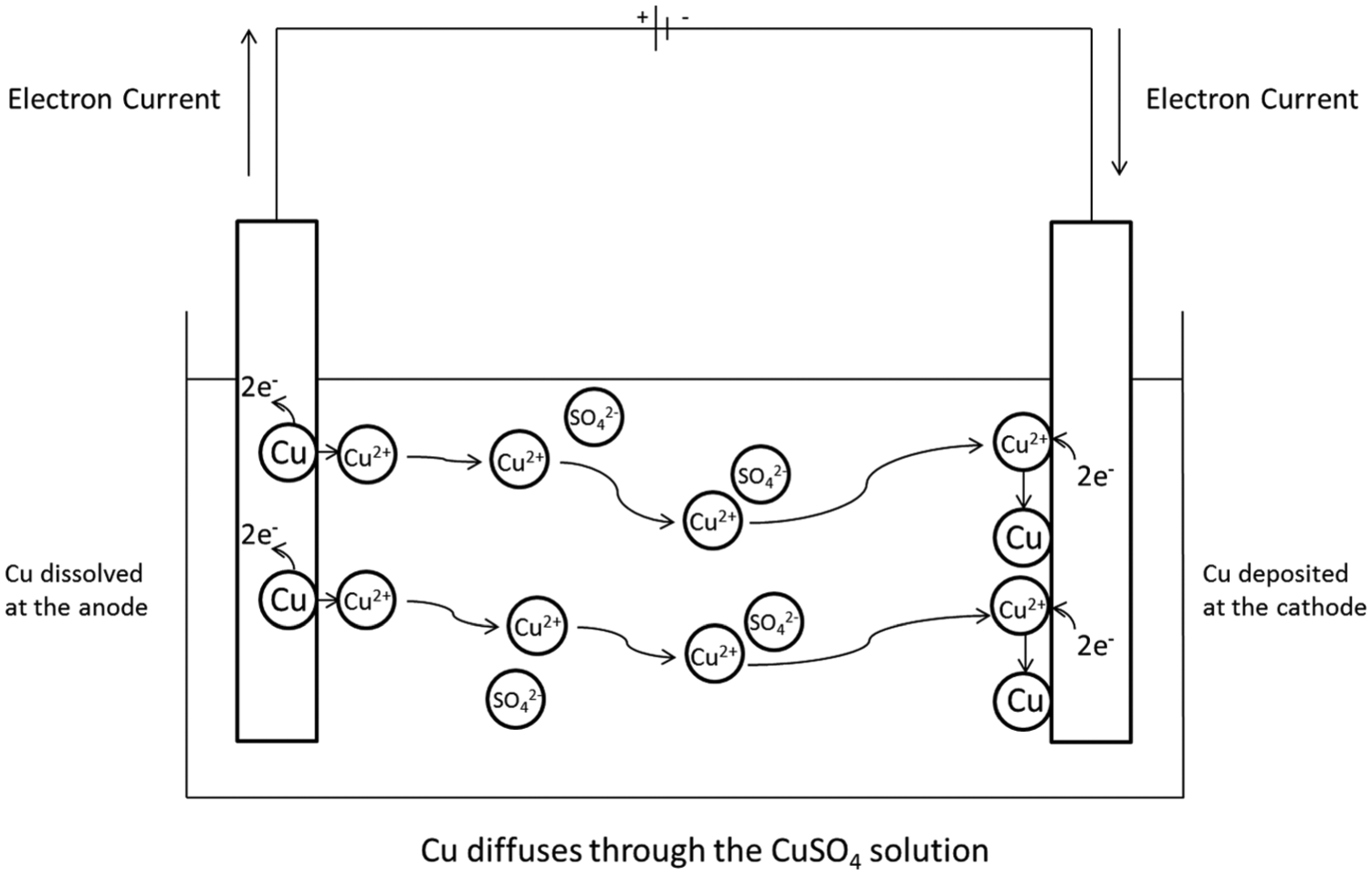
Schematic of copper purification process.
The impure copper anode is dissolved and hence reduces in mass. The insoluble impurities collect underneath the anode. No other reactions take place at either electrodes as copper is less reactive than hydrogen, as determined in the electrochemical series. 25 If a metal more reactive than hydrogen had been used, hydrogen gas would have been produced at the cathode, that is, if the standard potential of the half reaction relating to the working electrode material is negative with respect to hydrogen, hydrogen will be formed at the electrode. 28
ECM (removal of material) works on a similar basis as described above for the purification of copper. ECM utilises the anodic dissolution process used in copper electrolysis but confines the current, with different methods, to allow more precise and accurate dissolution. This enables different shapes and contours to be machined using this method.
Here, the controlled anodic dissolution of iron in sodium nitrate electrolyte will be used as an example to discuss the differences in the process compared to the electrolysis of copper. In order to control the areas on the workpiece which are affected by the anodic dissolution, the gap between the tool and the electrode is reduced to the micrometre range. This is one factor that helps to confine the current to the desired areas, making the process suitable for micromachining. The iron ions are dissolved in the same way as the copper ions; however, the two processes differ once the ions have been dissolved. In the electrolysis of copper, the ions remain in the solution until they are deposited onto the cathode. This is undesirable in the ECM process as it would alter the shape of the cathode tool over time. To avoid this, a cathode material which allows the electrolytic breakdown of water and the evolution of hydrogen is chosen. The hydrogen evolution reaction helps to balance the current flowing from the dissolution reaction at the anode and the electrolytic breakdown of water produces hydroxide ions. The iron ions react with hydroxide ions which have been formed from the electrolytic breakdown of water to form insoluble metal hydroxides. These precipitate out of the solution, removing the ions from the solution and preventing them from being deposited onto the cathode. This process, however, is not an electrochemical process, meaning it is a chemical reaction that will happen regardless of a current being passed and it does not occur at the electrode surface.2,5,29,30
The total current passed is not affected by this reaction. Figure 3 schematically shows the processes occurring during ECM of an iron workpiece in sodium nitrate.

Schematic for the anodic dissolution of iron.
The reactions occurring at the electrodes are as follows

The formation of the iron hydroxide happens away from the electrode surface and happens via the following electroless reaction

Electrolytes
The electrolyte has three main roles in the ECM process; it carries the current between the tool and the workpiece,4,25,31 it removes the products of the reaction from the IEG2,5,9,10,29,31–33 and it removes the heat produced from the passage of the current.2,4,5,9,10,31,34
The most common electrolyte used for ECM is a concentrated salt electrolyte, namely, sodium chloride or sodium nitrate. These are used as they are relatively inexpensive and they do not cause damage to the machinery. 10 An acidic electrolyte could corrode machinery over time. For electrochemical micromachining (ECMM), a less concentrated electrolyte is required to enhance the machining precision, by restricting the current passage through increased electrolyte resistance.
Sodium chloride is regularly used to machine stainless steel when a bright surface finish is required. Sodium chloride does not usually create a passive layer on the stainless steel surface which ensures fast, level machining of the surface. In contrast, sodium nitrate is used for machining stainless steel when close replication of the tool is of utmost importance. Sodium nitrate is a passivating electrolyte for stainless steel, but in this instance it prevents stray corrosion, ensuring precise tool replication. Using sodium nitrate, high current density favours anodic dissolution; however, low current density favours passivation. This is how sodium nitrate increases machining resolution compared to the same concentration of sodium chloride.
Lower concentration electrolytes are used to improve machining resolution.3,35–41 Resolution is improved due to the increased electrolyte resistance which requires shorter current paths for a given pulse length.
Trimmer et al. 35 used 0.05 M hydrochloric acid (HCl) to create sub-micron resolution structures on a nickel (Ni) substrate. This was achieved using 2-ns pulse duration with a 20-s pulse off time.
Bhattacharyya and Munda 36 observed a larger overcut with a more concentrated electrolyte, caused by an increase in current density.
Rathod et al. 37 machined micro-grooves with sulphuric acid with concentrations varying between 0.15 and 0.30 M. They also observed a decrease in machining resolution with the increase in electrolyte concentration. This was explained by an increase in electrical conductivity of the electrolyte, increasing the number of ions available for reaction.
Ma and Schuster 38 stated that machining resolution could be improved by increasing the specific electrolyte resistance, that is, reducing the concentration.
Thanigaivelan and Arunachalam 39 stated with 95% confidence that the electrolyte concentration has an effect on the overcut during machining.
Jain et al. 40 observed a decrease in machining localisation with an increase in concentration. However, beyond a limit, the machining localisation improved. It was suggested that the ion mobility is hindered due to the high electrolyte concentration.
Fan et al. 41 also observed an increase in machining overcut as the concentration increased when using sodium chloride with hydrochloric acid as the electrolyte to machine nickel plates.
Wu et al. 42 favoured a lower concentration electrolyte in the formation of nano-tips due to over etching in higher concentrations.
Wang et al. 43 stated that the electrolyte concentration affected the distribution of the current density, which, in turn, influences the machining resolution, with lower concentrations achieving better resolution.
Jain et al. 44 stated that the concentration affects the electrolyte conductivity and therefore the current density.
Ghoshal and Bhattacharyya 45 created micro-channels using ECMM. The authors observed the standard deviation of the micro-channel width reduced as the concentration increased; however, the overcut increased with increased concentration.
Ayyappan and Sivakumar, 46 however, found it beneficial to use a higher concentration as the surface finish was improved.
Formation of passivating layer
The choice of electrolyte determines the reactions that happen at both the workpiece and the tool electrode and also within solution. First, there are two main types of electrolyte; passivating and non-passivating electrolytes.9,10,24,33,47,48 Passivating electrolytes will encourage the development of a passive layer on the workpiece. A passive layer is usually formed of metal oxides and hydroxides which can spontaneously form upon contact with the electrolyte or once a current is flowing through the system. 49 This will depend on both the electrolyte and the metal involved. Many passive films are electrically insulating and form a barrier on the workpiece surface. This is usually detrimental to the machining process and in some cases can completely prevent any dissolution from occurring. This is not to say that the formation of all passive layers is unwanted. Sometimes the formation of a non-insulating passive layer can improve the resolution of the machining, obtaining a more precise shape with sharper edges and corners2,5,9,10,48,50 by increasing the resistance of the surrounding workpiece. This is beneficial for micromachining. The energy consumption for this method is higher due to the increased potential required to break through the passive layer. 22 A surface is said to be passive if the corrosion resistance is increased under conditions where bare metal would significantly react.22,25,49 Non-passivating electrolytes do not, as the name suggests, form a passive layer. They usually contain aggressive ions, such as chloride, which destabilises the formation of a film.5,9,10,22,25,47 This results in a higher machining rate, but the surface finish is compromised along with the machining resolution. 9
Passive layers are formed on the workpiece from the workpiece metal itself and components from the environment, usually water or oxygen dissolved in the electrolyte via the following reaction 49

The passive layer is usually formed of metal oxides and metal hydroxides. In some cases, the passive layer will form spontaneously and quickly, but in others the passive layer may only form when an anodic current is passed. This depends on both the electrolyte used and the metal the workpiece is made from. A passive layer is detrimental to the ECM process as passive layers increase the corrosion resistance of the surface, decreasing the material removal rate (MRR) and forces the potential higher in order to machine the surface. 22 This is because many passive films form a barrier and they show both low ionic and electronic conductivity at low and medium field strengths. If no current can be passed, either electronically or ionically, no reaction can occur and machining will stop. Not all passive films are insulating, some may conduct either electronically or ionically. The growth of insulating films is a self-inhibiting process, and usually a dense, homogeneous film of constant thickness is formed. However, an electrically conductive film will grow continuously; the thickness of the film will be proportional to the charge passed. Usually, a passive film will form a barrier which may be disrupted by a number of factors. When the field strength is high, dielectric breakdown can be observed, causing the oxide lattice to break down. Corrosion may weaken the film, but for ECM this is largely irrelevant as corrosion usually works on longer time scales than the experiment time frame. Although the effect of the electrolyte on the ECM equipment must be considered as these components are exposed to the electrolytes used over extended periods of time. The addition of aggressive ions to the electrolyte, such as chloride, may destabilise the film by penetrating the film. This has been observed to result in a more uneven surface finish as the penetration is not equal across the whole film. 49 This shows why choosing the correct electrolyte for the material to be machined is important. To achieve the highest MRRs using the least energy possible, the formation of passive films must be avoided. However, for precise replication of the tool in the workpiece, it may be best to use a passive electrolyte to increase the resolution of dissolution.
During the ECM process, the breakdown of the passive film may be indicated by irregular current peaks, visible sparks or an audible noise such as a cracking noise. It is dependent on the composition of the electrolyte and its concentration. However, the breakdown of the passive film is almost independent of the current density, temperature, surface roughness and hydrodynamics. 49
Researchers have been aware of the effect of passive films on the ECM process for a while and have tried to find ways to avoid or minimise their formation. The most common technique employed is to use a non-passivating electrolyte. Others have used a bipotentiostat to enable potential control of both the workpiece (anode) and the tool electrode (cathode). 17 This means the potential of the anode can always be held at a potential where the formation of a passive film is unfavourable and the potential pulses from the tool are superimposed over the potential of the anode. Because the anode is held at a potential where the formation of a passive layer occurs, the total charged passed is used for metal removal rather than removing the passive layer and underlying metal. This had the effect of increasing the MRR. This, however, is not necessarily the best option for ECMM; while high MRRs are important for processing times, it can compromise machining resolution. For micromachining, resolution is highly important.
Reasoning for selecting an electrolyte
There are four options for electrolytes:
Neutral aqueous salts
Aqueous acids
Aqueous bases or alkalis
Non-aqueous electrolytes
Aqueous salts are usually the first choice as they are generally inexpensive and tend not to cause damage to the machinery setup. However, when aqueous salt solutions do not provide an environment in which dissolution can occur, acidic or basic electrolytes can be used.
Acidic electrolytes are advantageous as the reaction products remain dissolved in the solution because the hydroxide ions produced at the cathode are neutralised by the high hydrogen ion (H+) concentration. This allows the IEG to be made as small as possible as it does not get clogged with solid reaction products (metal hydroxides).3,12,51 As a result, acidic electrolytes are preferred in ECMM. Sparks are also less likely to occur when using an acidic electrolyte due to the minimisation of sludge in the IEG.
Rathod et al. 37 used sulphuric acid as the electrolyte to machine micro-grooves in a stainless steel workpiece.
Alkaline electrolytes, such as sodium hydroxide (NaOH), are generally avoided as these can promote the formation of a passive film on the workpiece 52 and the high hydroxide concentration enhances the precipitation of metal hydroxides. This means the IEG has to be larger to prevent the space becoming clogged with the precipitate. Although some metal systems do show preferential dissolution in basic solutions, for example, tungsten carbide (WC) in potassium hydroxide (KOH). 42
Non-aqueous electrolytes eliminate the oxygen sources that form the passive films. 53 This is beneficial for passivating metals, but the conductivities of non-aqueous electrolytes are low due to the difficulties dissolving salts in them. 23
Sjöström and Su 54 used ethylene glycol as the electrolyte to machine titanium using a micro-sized tool. This eliminated heavy gas production allowing smaller IEGs to be used.
Fushimi et al. 55 studied the effects of various chloride containing salts in ethylene glycol for the dissolution of titanium. They found that increased water content increased the likelihood of a passive film forming on the titanium surface.
The concentration of the electrolyte can also affect the machining quality and rate.1,3,5 An electrolyte with a higher concentration can carry more current as there are more ions available within the solution.4,5,23 This means that the machining rate will be higher as the amount of material removed is proportional to the amount of current passed over time.2,33,56 The current lines extend further into the solution when the concentration is higher as the resistance of the electrolyte is reduced. This means the reaction at the workpiece can occur further away from the tool electrode which decreases the resolution of the machining process. 17 This issue has been overcome by the use of pulsed potential waveforms allowing the use of high concentration electrolytes to maintain high machining rates. 17
Schuster et al. 1 applied voltage pulses of only nanosecond duration with the intention of achieving micrometre resolution. They experimentally achieved a resolution of 1.4 µm with a 30-ns pulse.
When an alloy or sintered mixture of metals is used as a workpiece, choosing an appropriate electrolyte can be difficult. One electrolyte may be a good choice to machine one component of the alloy or mixture but may hinder the dissolution of the other components leading to an unevenly machined surface. A way to combat this is to use a mixed electrolyte. This has been successfully demonstrated by Choi et al. 51 in the machining of a tungsten carbide with cobalt binder (WC–Co) material. It was demonstrated that while sodium nitrate was a good electrolyte for the tungsten element, it encouraged the formation of an oxide film on the cobalt element. Sulphuric acid was added to the electrolyte at a concentration of 0.2 M which helped dissolve the cobalt binder allowing for even machining of the surface. Others have also demonstrated successful machining processes using mixed electrolytes.5,10,57,58
The electrolyte also serves the purpose of removing the reaction products from the machining gap. 14 The gap in ECM between the tool and the workpiece is very small, just a matter of micrometres, to enhance the resolution of the machining as explained above. This gap can very quickly become blocked with the solid metal hydroxides which are formed when the dissolved metal ions react with the hydroxide ions in solution. It is imperative to remove this precipitate from the IEG to prevent a short circuit occurring or causing damage to either the workpiece or the tool electrode through sparking. This is done by pumping the electrolyte through the gap to flush any precipitate or gas bubbles from the gap at a rate of 5–50 m s−1.2,4,10,14 This is carried out in different ways; the most popular way is to expand the IEG, pump electrolyte through in a pulse before closing the gap to its previous position.9,17,22,27 There is no electrolyte flowing while the electrodes are at their closest positions. Another method is to constantly pump the electrolyte through the system, but this requires a much sturdier tool electrode to prevent the tool from being misplaced or bent by the electrolyte flow. Flushing the electrolyte through the gap also reduces the thickness of the static diffusion layer at the electrode surfaces. This is beneficial as it increases the machining rate by reducing the time it takes ions to diffuse to the electrode surface from the bulk solution and vice versa.4,10,23,59
Electrolyte and current interaction
The third role of the electrolyte is to remove excess heat from the reaction zone. 5 Joule heating is the heat released when the current is passed through a conductor.4,5,18,59 The heat produced is proportional to the square of the current and the electrical resistance according to Joule’s first law

where Q is the amount of heat, I is the electric current flowing through the electrolyte, R is the electrical resistance of the electrolyte and t is the time the current is passed for. The heat is generated due to the resistance encountered when passing the current through the electrolyte.
There are several reasons as to why it is important to remove the heat from the IEG. One being to prevent the electrolyte from boiling in the gap;4,18,41,60,61 this creates bubbles in the gap,4,51 increasing the resistance across the gap and can cause sparks to occur between the two electrodes. This damages both the tool and the workpiece and can prevent any further machining taking place33,34 or confuse the control algorithm for the tool positioning/movement which is normally based on the constant electrolyte properties.
Another reason the temperature of the electrolyte needs to be controlled is to ensure the surface finish is of an acceptable standard. It was reported in a review article by J Bannard 5 that when the electrodes were heated above 40°C, the surface quality on the machined part was reduced. Hence, it is clear to see that the temperature needs to be controlled to enable good-quality machining to take place.
The temperature of the electrolyte affects the conductivity; electrolytic conductivity is temperature dependent.4,18,34 At higher temperatures, the conductivity of the electrolyte is raised. Having a higher electrolytic conductance allows a higher current to be passed through the electrolyte when applying the same potential between the two electrodes due to the relationship

This is because as the resistance of the electrolyte is decreased, the current increases to compensate for the resistivity drop. On the other hand, the same amount of current may be passed using a lower potential when the resistance is lower due to the same relationship. This is beneficial as the same machining rate can be achieved using less energy, increasing energy efficiency. However, using a higher machining rate reduces machining time and hence reduces costs associated with time and allows a higher throughput of products.
Researchers have found that using a higher voltage, however, does decrease the machining resolution15,37,39,51 but improves the surface finish. 48
IEG
In ECM, the IEG is of great importance. Many researchers have created models of the IEG as a way to predict how material will be removed, necessary as ECM is a non-contact process.6,18,41,62–65
Electrostatic field intensity
The amount of the material removed in ECM is dependent on the amount of current (I) that is passed at a particular point on the surface over time (t) and the charge (Q) that is passed as stated in Faraday’s law5,18,33,59

where m is the number of moles of reactant consumed or product formed, n is the number of electrons required for the conversion and F is the Faraday constant. The rate of the material removal is dependent on the current density that is, a higher current density results in a higher MRR. The current density is dependent on the potential ‘felt’ at the surface.4,5,25 The potential at the workpiece surface is lower than that applied by the cathode due to potential losses. 4
Figure 4, from Engineer on a Disk, 66 shows how the potential changes through the solution with respect to the distance between the electrodes. As can be seen from Figure 4, the smaller the inter-electrode distance, the smaller the applied potential has to be to reach the machining potential as the ohmic drop caused by the electrolyte resistance is reduced. This is used to the researchers’ advantage. There is preferential dissolution of the material which is closer to the tool electrode due to the higher potential creating a higher current density at that point. This is a very important point to be considered when the process is used for micro manufacturing.3,67,68 Using a smaller IEG exploits this known behaviour, with greatly increased machining rates on the workpiece at positions closest to the tool electrode. Using a small IEG along with pulsed voltage allows greater machining resolution to be achieved, something demonstrated by Schuster et al. 1

Potential profile within the inter-electrode gap. Redrawn from Engineer on a Disk. 66
Figure 4 shows a large potential drop at the electrode surfaces. This is due to the presence of an electrical double layer (EDL).22,23,51,69 An EDL is formed when a potential is applied to an electrode causing the electrode surface to become charged. This attracts oppositely charged ions and dipoles in the electrolyte to the electrode surface. The organisation of these ions and dipoles at the surface determines the distribution potential as a function of distance from the electrode surface. 23
When a constant potential is applied, the material on the workpiece which is most strongly polarised by the tool is dissolved first. As time is passed, the material further away from the tool is machined. It is for this reason that a tool with insulated sides is important to produce a hole with minimal tapering.3,12,17,22,37,43,70–74 If the sides of the tool were not insulated, the hole produced would be tapered, with a larger opening in comparison to the exit due to the increased length of time the material is exposed to the electric field.
PECM
One way to minimise the overcut produced in ECM is the application of a pulsed voltage rather than a constant potential.1,6,8,12,17,37,41,51,54,70,73,75–78 Using a pulsed voltage allows the IEG to be reduced, which, as already discussed, facilitates higher machining resolution, by restricting the areas on the workpiece which are sufficiently charged for anodic dissolution to occur.
Electrochemical reactions are exponentially dependent on the potential drop in the double layer.1,14,17,22 During ultra-short potential pulses, the EDLs are charged and discharged periodically. The time constant (τ) for charging the double layers is small enough for significant charging at only very small electrode separations in the nano- to micrometre range. The time constant defines the length of time for the EDL to be fully charge and is dependent on electrode separation and the electrolyte resistance. It is defined by the following equation

where
This means reactions are confined to the polarised regions which are very close to the tool electrode surface. The time constant, describing the time taken for the double layer at a working electrode to charge or discharge, is the product of the electrolyte resistance along the current path and the double-layer capacitance and therefore varies linearly with the separation between the electrodes.1,14,18,22,69 Using a shorter potential pulse requires the use of a smaller IEG to reduce the resistance encountered in the electrolyte, allowing sufficient charging of the double layer on the working electrode surface. L Cagnon et al. 22 achieved a precision of 200 nm using a 5-ns pulse on stainless steel.
Pulses longer than 1 ms are also used; however, the resolution is no longer dependent on the double-layer charging but dependent on the diffusion layer. Over time, the diffusion layer grows, using the material farther from the cathode. 23
Models of the IEG
Models of the IEG in ECM are complex, combining many different factors including influences of the electrolyte properties; the electrolyte properties are affected by gas bubble formation and the electrolyte temperature and concentration. These are, in turn, affected by the electrolyte flow rate through the IEG.
Models agree that the IEG can be pictured as two parallel plate capacitors which represent the EDLs at the electrode surfaces. 79 Kozak et al. 80 added non-linear resistors in parallel with the capacitors, as can be seen in Figure 5. The current passed during each potential pulse can be split into two currents. The first is the charging current; this provides the energy needed to rearrange the ions in the EDL to counter the charge at the electrode surface due to the potential change.23,69

Electrical model of the inter-electrode gap proposed by Kozak. Redrawn from Kozak et al. 80
This current does not lead to any chemical change or any material removal. The second is the Faradaic current; this current is responsible for the electrochemical reactions that occur at the electrode surface. It is this current that is used to monitor the IEG distance, as Faradaic current only starts flowing once the EDL is fully charged.41,78,79
Material removal efficiency
With a higher current being passed, the current density is increased which means the amount of energy reaching the electrode surface per unit of time is increased. This, in turn, increases the rate of material removal. This is beneficial due to reduced machining times. However, if the current density is too high, the surface finish can be compromised.3,59 Sparks can occur between the tool and workpiece if the current is too high or the IEG is too small. Sparks cause damage to both the tool and the workpiece
In electrolysis, the amount of substance that reacts is proportional to the current passed and the length of time the current is passed for, that is, the charge that is passed. It is also proportional to the valency of the reactant or how many electrons are needed in the reaction. 2 The amount of material removed is calculated through the following equation
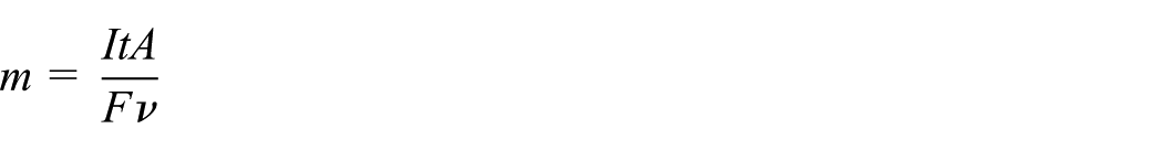
where m is the amount of material removed, I is the current passed, t is the time passed, A is the atomic weight, F is the Faraday constant and υ is the valency.
If there is only one reaction happening at the workpiece electrode, one can expect the current efficiency to be close to 100% or 100%. Lower current efficiencies can indicate another reaction taking place simultaneously or that the products reach a higher valency than predicted, that is, Fe3+ is formed rather than Fe2+. In some cases, current efficiencies higher than 100% have been reported. This is possible as current efficiencies in ECM are defined as the ratio of the observed mass change to the theoretical mass change predicted from Faraday’s I law assuming 100% current efficiency for the anodic dissolution

where k is the electrochemical equivalent of the workpiece material which equals the mass of ions carrying 1 C of electric charge over the time period
Limitations of ECMM
As discussed, ECM is a difficult-to-control process due to stray corrosion. Resolution has been improved through the application of micrometre-scale IEGs to enhance the current distribution on the workpiece to areas in close proximity to the tool electrode. The application of voltage pulses has also improved machining resolution by restricting the areas of the workpiece which become sufficiently charged to facilitate anodic dissolution.
The maximum resolution achieved with ECMM is 200 nm through the application of 5-ns pulses. 22
It is also imperative for users to accurately measure the IEG throughout machining. The IEG affects machining resolution, as previously discussed. Researchers have proposed differing methods for IEG control from a fuzzy logic approach, 81 monitoring the machining current,73,82 periodically checking the IEG through electrical conductivity measurements, 36 monitoring the potential between the two electrodes 83 and using ultrasound as a way to probe the machining gap. 84 Without proper gap monitoring, there is a risk the tool will contact the workpiece, causing either a short circuit or a spark which can damage the electrodes and deteriorate the surface finish.
Machining accuracy is also affected by tool clamping. Micro-tools are necessary for ECMM, but holding these tools in place is difficult while knowing their exact position. This has been somewhat overcome by on-machine fabrication of the tools. 85
Stray machining also affects the process’s ability to create sharp edges and corners. Insulating the tool has helped somewhat in minimising tapering of micro-holes, as has the application of a dual-pole tool. 86
Conclusion and discussion
From the review process described above, it was shown that already many researchers have successfully demonstrated the use of ECM in manufacturing micro features on surfaces through the use of a pulsed potential in combination with a small IEG. Features as small as 0.5 µm have been produced with ECM 38 indicating ECM is a viable technique for micro manufacturing.
However, it is unknown what methodology to be used and which electrolyte should be used for a particular metal choice with researchers focusing only on one metal or alloy to determine ideal machining parameters. If a new material were to be machined, extensive research to establish a suitable electrolyte along with appropriate machining parameters such as applied potential and pulse length needs to be done. At present, there is no scientifically based methodology to justify the use of specific electrolyte solution, IEG distance and machining conditions especially for the needs of micro manufacturing application of ECM technology.
Very little work has also been conducted on ECM machining of the semiconductor materials outside of the doped silicon materials. A wide range of semiconductor materials are being used more commonly in electronic equipment, some of which are brittle and difficult to machine with conventional machining processes. It is proposed to determine whether ECM is a suitable machining method for some of these semiconductors, including indium antimonide (InSb) and gallium arsenide (GaAs).
Another interesting field is the machining of superconductors. Most high-temperature superconductors are based on the perovskite crystal structure with internal layers throughout the structure which are crucial to the superconductivity of the material. Traditionally, contact machining techniques can damage these layers through the application of physical pressure on the material. ECM is an ideal technique for machining superconductors as it is a non-contact, stress-free and heat-free technique. Also, there has been no work, to the author’s knowledge, investigating the effect of crystal structure, comparing the results obtained in ECM for polycrystalline, monocrystalline and amorphous materials. This would be of interest with the aim to developing more precise machining results and manufacturing of micro-electromechanical systems (MEMS) devices as well as testing the boundaries of archived roughness and feature size.
Footnotes
Academic Editor: Hui Ding
Declaration of conflicting interests
The author(s) declared no potential conflicts of interest with respect to the research, authorship, and/or publication of this article.
Funding
The author(s) disclosed receipt of the following financial support for the research, authorship, and/or publication of this article: The research reported in this article was supported by the European Commission within the project ‘Minimizing Defects in Micro-Manufacturing Applications (MIDEMMA)’ (FP7-2011-NMP-ICT-FoF-285614).