
Abstract
Micro-dimple arrays with specific shapes and dimensions are crucial for reducing wear and vibration. Through-mask electrochemical machining (TMECM) using flexible cathodes removes materials based on anodic dissolution and allows for efficient processing of large-area micro-dimple arrays. However, the flexible cathode’s tight adherence to the mask can cause sludges from the processing area to stick or aggregate on the cathode surface, which can affect the processing localization of the micro-dimple array. This work introduces a method for TMECM using flexible cathodes which synchronizes the power switching with the cathode movement. Experiments on TMECM were conducted to investigate the changes in the distribution of sludges on the cathode surface. The processing time window for the adhesion and aggregation of sludges was identified. Moreover, the influences of sponge characteristics and processing parameters on micro-dimple machining were investigated. Rules governing the changes in micro-dimple diameter, depth, and bottom surface roughness concerning the sponge’s pore density, compression amount, power conduction time, and effective processing time were established. Ultimately, by adjusting the sponge characteristics and processing parameters, a high-precision micro-dimple array with a diameter of 229.6 ± 2 μm, a depth of 9 ± 0.3 μm, and a bottom surface roughness Sa of 0.34 μm and Ra of 0.43 μm was fabricated.
Keywords
Introduction
Surface characteristics significantly impact the fatigue strength, and friction-wear performance of parts, playing a crucial role in determining the reliability, and durability of components. 1 The fabrication of microstructures on the surface of parts, ranging from micron or nanoscale to millimeter scale, significantly enhances the operational performance of the parts. 2 However, due to the constraints of material hardness and rigidity, many are difficult to process using mechanical cutting methods. 3 In electrochemical machining (ECM), the cathode does not contact the workpiece, free from the constraints of the workpiece’s mechanical properties. Moreover, ECM can prevent the thermal stress and recast layer that frequently occur in electrical discharge machining and laser machining. Therefore, it has significant advantages in the processing of surface microstructures. 4 However, different ECM methods have specific applications and technical challenges. The die-sinking ECM method allows for the efficient fabrication of diverse three-dimensional surface microstructures by altering the cathode structure. However, the constraining stray electric fields remain challenging.5–7 The method of maskless ECM utilizes the movement of a cathode with an insulation layer to generate large-scale microstructures on the workpiece surface. However, precision is required in the relative position between the cathode and the workpiece surface.8–10 The through-mask electrochemical machining (TMECM) method can efficiently produce micro-dimple and micro-protrusion arrays at a repeatable scale. However, the processing localization remains low, and dimension uniformity is also poor. 11
To improve the localization of TMECM, researchers have recently focused on enhancing cathode characteristics, optimizing mask structures, controlling electrolyte flow, and employing auxiliary energy fields. In terms of improving the characteristics of cathodes, Zhang et al. 12 utilized porous cathodes to remove electrolytic products and generated micro-dimple arrays with diameters ranging from 107 to 114 μm and depths of 5 to 10 μm. Chen et al. 13 fabricated micro-channel arrays with a width of 330 μm and a depth of 45 μm by covering the workpiece surface with a masked porous cathode. Singh Patel et al. 14 achieved a tight fit between the fabric cathode and the mask by squeezing sponges, utilizing reciprocating punch movement to generate shear flow in the processing area to accelerate product removal. In optimizing mask structure, Zhao et al. 15 applied rib-connected masks to TMECM. By optimizing processing parameters, they achieved the fabrication of micro-cone arrays with a high aspect ratio of 10.28 and a standard deviation of 0.22. Wang et al. 16 conducted a numerical simulation of the electric field to analyze the effects of mask aspect ratio and the inter-electrode gap on the machining process. Mahata et al.17,18 utilized AZ-4903 material to fabricate low-aspect-ratio masks for processing micro-dimple arrays, with an overcut of 29.15 μm and a depth of 32.15 μm. In controlling electrolyte flow, Pan et al. 19 employed the high-pressure static electrolyte for TMECM, producing an array of 14,000 micro-dimples with a diameter of 105.95 μm and a depth of 9.79 μm. Wu et al. 20 introduced a mask electrolyte jet machining method, analyzing the impact of nozzle movement on the machining process through coupling simulations, and fabricated high-precision, highly consistent micro-convex and micro-concave arrays. He et al. 21 utilized a jet mask ECM method to prepare micro-hole arrays on the surface of Zr702 zirconium alloy workpieces, with an average pore diameter of 152.11 μm and an average pore depth of 76.13 μm. In the field of auxiliary external energy, Wang et al. 22 introduced ultrasonic stirring into TMECM, investigating the impact of ultrasonic frequency, and amplitude on the mass transfer process. Zhai et al. 23 introduced mega sonic vibration into TMECM and prepared an array of micro-dimples with an average diameter of 167.77 μm, a depth of 79.62 μm, and an etching factor as high as 2.35. Du et al. 24 introduced a particle-assisted TMECM method to fabricate micro-dimple arrays and achieved a maximum dimple depth of 58 μm and an etching factor of 2.4.
The method for improving the performance of TMECM, which involves using a flexible porous cathode, enables the cathode to adaptively, and tightly fit with the mask, thereby facilitating the processing of microstructures on both flat and curved workpieces, demonstrating good processing adaptability. However, it’s crucial to consider that the electrolyte flowing through porous areas will encounter significant flow resistance, making it challenging to refresh the electrolyte and remove sludges within the processing area. Moreover, due to the flexible porous cathode being tightly attached to the mask, sludges randomly adhere or aggregate on the cathode surface. It blocks the conduction of current in the processing area, significantly worsening the processing consistency of the surface microstructure. By enhancing the electrolyte flow and employing external energy fields, the refreshment of the electrolyte within the processing area can be accelerated. However, the sludges randomly distributed on the cathode surface remain challenging to remove. Therefore, this work introduces a method for TMECM using flexible cathodes, which synchronizes power switching with the cathode movement. When the cathode is in close contact with the mask, the power source is turned on to create micro-dimples on the workpiece surface. When the cathode moves away from the mask, the power source is shut off to rinse off the sludges attached to the cathode surface. In the TMECM experiments, an investigation was conducted on the distribution pattern of sludges on the cathode surface when the cathode was closely fitted to the mask. Moreover, this work investigated the effects of pore density and compression amount of the sponge on micro-dimple machining when power switching and cathode movement were controlled synchronously. This work also analyzed the impacts of power conduction time and effective processing time on micro-dimple machining. Ultimately, based on the TMECM experiments, optimized conditions were obtained to enhance the localized precision of micro-dimple array machining.
Methods and materials
TMECM method
The process of TMECM using flexible cathodes is shown in Figure 1. In the initial stage, due to the tight adherence of the flexible cathode to the mask, the distribution of electric field lines within the processing area is relatively uniform, which facilitates the uniform dissolution of the workpiece material. During the stable stage, sludges and bubbles continuously accumulate in the processing area. Some sludges even adhere to the flexible cathode surface, making electrical conduction increasingly difficult and decreasing the electric field strength within the processing area. During the termination stage, sludges on the flexible cathode surface aggregate, causing a large amount of by-products to remain within the processing area. This blocks the conduction of the machining current, resulting in the cessation of material dissolution and the formation of surface microstructures.

Schematic diagram of TMECM using flexible cathodes. (a) Initial stage. (b) Stable stage. (c) Terminal stage.
To address the challenges in TMECM using flexible cathodes, such as the difficulty in discharging sludges and the tendency for sludge adhesion or aggregation on the cathode surface, a synchronous control method for power switching and cathode movement as shown in Figure 2 is proposed. te represents the effective processing time and is an integer multiple n of the power conduction time tc.

Schematic diagram of synchronous control for power switching and cathode movement.
As shown in Figure 3, the flexible cathode wraps around the bottom of the porous sponge, and the upper end is assembled into the electrolyte chamber and in contact with the electrolyte separation plate inside the electrolyte chamber. Assembles the plastic gasket from the bottom of the flexible cathode and connects it to the electrolyte chamber as a whole through fastening screws. As depicted in Figure 3(a), during the power conduction time tc, the porous sponge drives the flexible cathode to adhere to the mask closely and applies a voltage U to remove the workpiece material and generate electrolytic products. As depicted in Figure 3(b), during the power-off time, the flexible cathode retracts, its displacement relative to the mask is S, and the workpiece material does not dissolve. The power-off time is usually more than 4 s to ensure that the sludge on the cathode surface is washed away by a high-pressure electrolyte and maintains its good conductivity. By controlling the synchronization of power switching and the cathode movement within the processing time t, it is possible to achieve periodic intermittent dissolution of the workpiece material while preventing the adhesion or agglomeration of sludges on the cathode surface. However, it should be noted that the power conduction time required to prevent the adhesion or agglomeration of sludges is still unclear. Similarly, the characteristics of the flexible cathode, the properties of the sponge, and the processing parameters that are beneficial for the machining of micro-dimple arrays remain uncertain. Therefore, by conducting experiments on TMECM, the distribution patterns of sludges on the cathode surface and the evolution characteristics of micro-dimple contours were investigated to identify optimal processing conditions.

Process of the flexible cathode adhering to and moving away from the mask. (a) Fit state. (b) Separation state.
Experimental system for TMECM
The experimental system for TMECM using flexible cathodes is depicted in Figure 4. The system comprises the machine tool body, programmable power supply, electrolyte circulation and filtration system, and processing devices within the working chamber. The electrolyte chamber and flexible cathode are driven in a vertical direction for feeding and retracting movement using a motion controller and servo motor. The workpiece covered by the mask is fixed on the granite platform through the baseplate. In achieving synchronized control of power switching and cathode movement, it is essential to make adjustments to the conduction and cut-off time of the programmable power supply, as well as the movement pattern of the flexible cathode. The synchronous control method of power supply and z-axis motion is shown in Figure 5. Independently sets the motion program for the z-axis and the on/off time of the power supply. When the z-axis drives the flexible cathode to reach the retraction position, the dwell time at the retraction position corresponds to the power-off time. When the z-axis drives the flexible cathode to move rapidly and the flexible cathode stays in the processing area, the program running time corresponds to the power conduction time. By setting up a reciprocating motion program and repeatedly turning on and off the power supply, synchronous control of flexible cathode motion and power supply on and off can be achieved. Moreover, the electrolyte is transported to the unmasked areas on the workpiece surface through an electrolyte separation plate, a porous sponge, and a flexible cathode set inside the electrolyte chamber.

Schematic diagram of the experimental system for TMECM.

Synchronous control of power supply and z-axis motion.
Considering that the sponge should have good electrolyte permeability, elastic deformation performance, and wear resistance, a polyurethane sponge as shown in Figure 6 was employed with a pore density between 10PPI and 50PPI. The silver-coated flexible cathode employed, as shown in Figure 7, was prepared by forming a dense silver coating on the surface of woven polyamide fabric through an electroless silver plating process. The silver-coated flexible cathode had a silver content of 15% and a resistance of 0.26 Ω/cm. Using the femtosecond laser method, a circular array of hollow patterns was processed on a polyimide mask with a thickness of 100 μm as shown in Figure 8. The diameter of the holes was 200 μm, and the spacing was 500 μm, with both the diameter, and spacing errors controlled within 1 μm.

Polyurethane sponges with different pore densities. (a) 10PPI. (b) 20PPI. (c) 30PPI. (d) 40PPI. (e) 50PPI.

Silver-plated flexible cathode.
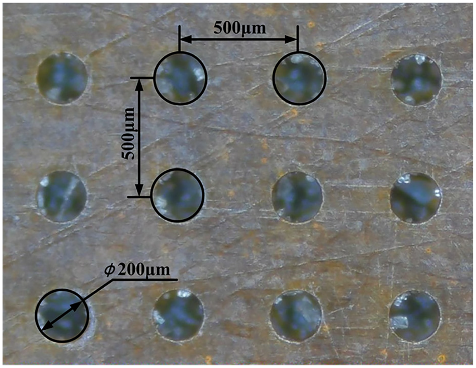
Polyimide mask.
Continuous processing experiments for TMECM
The distribution characteristics of sludges on the flexible cathode surface were analyzed through continuous processing experiments, and the flexible cathode remains in constant contact with the mask during the continuous processing time. The experiments employed an applied voltage of 10 V, a sponge’s pore density of 50PPI, a compression amount of 5 mm, and an electrolyte inlet pressure of 0.15 MPa as processing parameters. The workpiece material is SS304. Moreover, the distribution states of sludges were observed using a high-definition industrial microscope for continuous processing times ranging from 4 to 24 s.
TMECM experiments with synchronous control of power switching and cathode movement
Based on the investigation of sludge distribution, experiments were carried out to synchronously control power switching and cathode movement. The effects of the sponge’s pore density and compression amount on micro-dimple diameter, depth, and bottom roughness were analyzed. The pore density ranged from 10PPI to 50PPI, and the compression amount ranged from 1 to 5 mm. Moreover, the impacts of power conduction time and effective processing time on micro-dimple diameter, depth, and bottom surface roughness were examined. The power conduction time tc ranged from 4 to 12 s, with a shut-off time of 4 s, and the effective processing time te varied from 16 to 80 s. The primary processing parameters employed in the TMECM experiment are presented in Table 1.
Primary processing parameters of TMECM.

Detection of micro-dimple arrays
Figure 9 illustrates a schematic for detecting micro-dimples. The contours of micro-dimples were inspected using a high-definition industrial microscope and an Olympus DSX100 ultra-depth-of-field microscope to measure the diameter da and depth ha. Moreover, the DSX100 image processing software was employed to analyze the micro-contour features at the bottom of the micro-dimples, obtaining the surface roughness Sa and Ra at the center position of the micro-dimple bottom. The sampling area for roughness measurement was set at 100 μm × 100 μm. The detection of surface roughness Sa complies with the ISO 25178-2-2012 standard, and the detection of surface roughness Ra complies with the GB/T 1031-2009 standard.
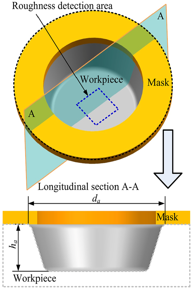
Schematic diagram of micro-dimple detection.
Results and discussion
Distribution of sludges on the flexible cathode surface
Figure 10 illustrates the distribution of sludges on the flexible cathode surface at different continuous processing times. It can be seen from Figure 10 that as the continuous processing time increased from 4 to 24 s, the coverage area of the sludge on the cathode surface generally showed an increasing trend. When the continuous processing time was between 4 and 8 s, most areas of the flexible cathode surface adhered to a yellow-brown sludge containing iron oxides and complexes. When the continuous processing time exceeded 12 s, not only did sludge adhesion occur, but also localized agglomeration of sludges happened. It severely damages the conductivity of the flexible cathode, preventing electrochemical reactions from occurring in certain areas between the cathode and the workpiece surface.

Distribution of sludges on the cathode surface at different continuous processing times. (a) t = 4 s. (b) t = 6 s. (c) t = 8 s. (d) t = 12 s. (e) t = 16 s. (f) t = 24 s.
From the continuous processing experiments, it is evident that due to the flexible cathode being closely attached to the mask, as the continuous processing time increases, the anodic reaction products within the processing area gradually diffuse to the cathode surface. It leads to the adhesion and aggregation of sludges on the cathode surface, causing local micro-dimple processing to cease, thereby severely affecting the processing consistency of the micro-dimple array. Therefore, in subsequent experiments, synchronous control of power switching and cathode movement was implemented, with the cathode retraction displacement set to 10 mm.
Influence of sponge’s pore density on micro-dimple machining
Figure 11 illustrates the variations in diameter, depth, and surface roughness of micro-dimples with different pore densities. The sponge’s compression amount was 3 mm, the power conduction time tc was 8 s, and the effective processing time te was 48 s. As shown in Figure 11(a), it is evident that as the pore density increased from 10PPI to 50PPI, the diameter and depth of the micro-dimples showed an initial increase followed by a decrease. Moreover, there was a significant reduction in the deviation in diameter and depth of the micro-dimples. When the pore density was 30 PPI, the diameter of the micro-dimples was 252.7 μm, and the depth was 11.4 μm; when the pore density was 50 PPI, the diameter was 231 μm, and the depth was 7.8 μm. As can be seen from Figure 11(b), with the increase in pore density, the roughness values of the micro-dimple bottoms generally showed a decreasing trend. When the pore density was 50PPI, the surface roughness Sa was 0.329 μm and Ra was 0.419 μm. Figure 12 shows the micro-dimple arrays processed with varying pore densities. As shown in Figure 12, it is evident that the cross-sectional profile of the micro-dimples tended to be trapezoidal, rather than the semi-circular shape seen in traditional TMECM. Moreover, there were no noticeable residual protrusions at the bottom of the micro-dimples.

Micro-dimple dimensions and roughness at different pore densities. (a) Diameter and depth of micro-dimples. (b) Surface roughness.

Micro-dimple arrays processed with different pore densities. (a) 10PPI. (b) 20PPI. (c) 30PPI. (d) 40PPI.
The influence of the sponge’s pore density on the machining of micro-dimples reveals that when the pore density approaches 30PPI, the electrolyte permeation within the sponge is more efficient. Fresh electrolytes can quickly enter the processing area, resulting in micro-dimples with larger diameters and depths. As the pore density increases to 50PPI, there is a notable rise in the flow resistance of the electrolyte within the sponge. This increased resistance presents challenges in supplying electrolytes to the processing area, leading to a significant decrease in both the diameter and depth of the micro-dimples. However, the increased flow resistance also leads to decreased flow field fluctuation, which is advantageous for the uniform dissolution of the workpiece material. Thus, the deviation in micro-dimple diameter and depth is significantly reduced, and there is a notable decrease in the surface roughness value. Moreover, increasing the pore density can enhance the contact area between the sponge and the flexible cathode, thereby promoting even adhesion of the flexible cathode to the mask. This enhancement contributes to a more uniform distribution of the electric field within the processing area and diminishes stray corrosion during machining.
Influence of sponge’s compression amount on micro-dimple machining
Figure 13 illustrates the variations in micro-dimple diameter, depth, and surface roughness for different compression amounts. The sponge’s pore density was 50PPI, the power conduction time tc was 8 s, and the effective processing time te was 48 s. As shown in Figure 13(a), it is evident that with an increase in compression amount from 1 to 5 mm, the diameter of the micro-dimples first decreased from 246.9 to 232.5 μm, and then stabilized between 229 and 232.5 μm. Whereas the depth of the micro-dimples experienced a sharp decrease, followed by a slow increase. Moreover, a noticeable reduction in deviation was observed in both the diameter and depth of the micro-dimples. When the compression amount was 1 mm, the micro-dimple diameter was 246.9 μm, and the depth was 14.6 μm; when the compression amount was 5 mm, the diameter was 229.6 μm, and the depth was 9.05 μm. It can be observed from Figure 13(b) that as the compression amount increased, the roughness value at the bottom of the micro-dimples initially decreased before gradually stabilizing. When the compression amount was 5 mm, the surface roughness Sa was 0.342 μm and Ra was 0.43 μm. Figure 14 shows micro-dimple arrays processed with different compression amounts. From the changes in the cross-sectional profiles of the micro-dimples, it is evident that when the compression amount increased from 1 to 2 mm, both the diameter, and depth of the micro-dimples significantly decreased. Whereas, when the compression amount exceeded 2 mm, the changes in the cross-sectional profiles of the micro-dimples were minimal, and the shape of the cross-section tended to be trapezoidal.
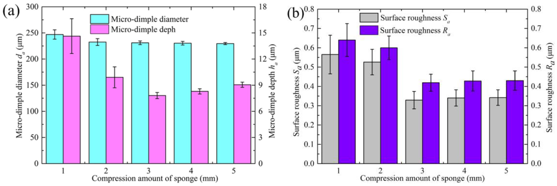
Micro-dimple dimensions and roughness for different compression amounts. (a) Diameter and depth of micro-dimples. (b) Surface roughness.

Micro-dimple arrays processed with different compression amounts. (a) 1 mm. (b) 2 mm. (c) 3 mm. (d) 4 mm.
The influence of the sponge’s compression amount on micro-dimple machining shows that with a small compression amount, the deformation of the sponge pores is minimal. It results in a relatively sufficient supply of electrolytes in the processing area due to the action of the electrolyte pressure gradient, leading to larger diameter and depth of the micro-dimples. However, due to the small compression amount of the sponge, it is difficult for the flexible cathode to fully compress and adhere closely to the mask, resulting in significant differences in material removal rates across different processing areas. Thus, there are substantial deviations in the diameter and depth of micro-dimples, and the surface roughness values of the bottom are also relatively high. As the compression amount of the sponge increases, the flexible cathode and the mask fit closely together. It significantly improves the uniformity of the electric field distribution in the processing area, resulting in a more uniform dissolution of the workpiece material. Thus, the diameter and bottom surface roughness of the micro-dimples tend to stabilize. Moreover, although the flow resistance of the electrolyte within the sponge increases with the compression amount, the rapid compression of the sponge enhances the shear flow of the electrolyte in the processing area, promoting the dissolution of micro-dimples along the depth direction. Hence, the depth gradually increases.
Influence of power conduction time on micro-dimple machining
Figure 15 depicts the variations in the diameter, depth, and surface roughness of micro-dimples at different power conduction times. The sponge’s pore density was 50PPI, the compression amount was 5 mm, and the effective processing time te was 48 s. As can be seen from Figure 15(a), as the conduction time increased from 4 to 12 s, the diameter of the micro-dimples, the deviation in diameter, and the deviation in depth all initially decreased before increasing. Meanwhile, the depth of the micro-dimples was significantly reduced. When the conduction time was 4 s, the micro-dimple diameter was 238.3 μm, and the depth was 14.99 μm; when the conduction time was 12 s, the diameter was 242.6 μm, and the depth was 7.49 μm. As shown in Figure 15(b), as the conduction time increased, the roughness value of the micro-dimple bottom first stabilized before rapidly increasing. When the conduction time was 12 s, the surface roughness Sa was 0.46 μm and Ra was 0.54 μm. Figure 16 displays micro-dimple arrays processed with different conduction times. From the changes in the cross-sectional profile of the micro-dimples, it is evident that when the conduction time was short, the micro-dimples underwent intense dissolution along the diameter and depth directions, leading to a cross-sectional shape that tended toward a trapezoid. As the conduction time increased, the dissolution of the micro-dimples in the depth direction became restricted, resulting in a more flattened cross-sectional shape.

Micro-dimple dimensions and roughness at different power conduction times. (a) Diameter and depth of micro-dimples. (b) Surface roughness.

Micro-dimple arrays processed with different power conduction times. (a) tc = 4 s. (b) tc = 6 s. (c) tc = 10 s. (d) tc = 12 s.
It is evident from the influence of conduction time on micro-dimple machining that when the conduction time is short, the frequency of flexible cathode feeding and retraction increases. Frequent compression of the sponge enhances the shear flow of the electrolyte in the processing area, promoting product removal and uniform dissolution of workpiece materials. Thus, micro-dimples have large diameters and depths, while the surface roughness values are small. As the conduction time increases, sludges and bubbles are more likely to build up in the processing area, blocking the conduction of the machining current. This not only intensifies the unpredictability of micro-dimple dissolution, but also results in an increase in the deviations of micro-dimple diameter and depth, and surface roughness value.
Influence of effective processing time on micro-dimple machining
Figure 17 shows the changes in diameter, depth, and surface roughness of micro-dimples at different effective processing times, with a sponge’s pore density of 50PPI, a compression amount of 5 mm, and a power conduction time tc of 8 s. As shown in Figure 17(a), it is clear that as the effective processing time increased from 16 to 80 s, the diameter and depth of the micro-dimples significantly increased. Meanwhile, the deviation in diameter and depth decreased initially and then increased. When the effective processing time was 16 s, the micro-dimple diameter was 218 μm, and the depth was 3.52 μm; when the effective processing time was 80 s, the diameter increased to 260.54 μm, and the depth rose to 12.25 μm. It can be seen from Figure 17(b) that the roughness value of the micro-dimple bottom decreased significantly and tended to stabilize as the effective processing time increased. When the effective processing time was 80 s, the surface roughness Sa was 0.332 μm and Ra was 0.417 μm. Figure 18 shows the micro-dimple arrays fabricated with different effective processing times. From the changes in the cross-sectional profile of micro-dimples, it is evident that when the effective processing time was short, there were significant residual protrusions at the bottom of the micro-dimples. As the effective processing time increased, the bottom of the micro-dimples tended to become smooth.

Micro-dimple dimensions and roughness at different effective processing times. (a) Diameter and depth of micro-dimples. (b) Surface roughness.
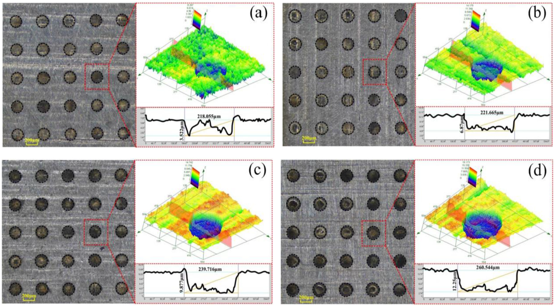
Micro-dimple arrays processed with different effective processing times. (a) te = 16 s. (b) te = 32 s. (c) te = 64 s. (d) te = 80 s.
From the influence of effective processing time on micro-dimple machining, it is clear that as the effective processing time increases, the electric quantity in the processing area gradually increases. According to Faraday’s law and Coulomb’s law, the diameter and depth of the micro-dimple also significantly increase. When the effective processing time is short, the dissolution of micro-dimples does not enter a stable state, their depth is relatively shallow, and there are significant deviations in diameter and depth, as well as high values for bottom surface roughness. When the effective processing time is overly long, the electric field energy on the surface of the micro-dimples significantly decays and disperses with the increase in the inter-electrode gap, leading to a notable increase in deviations in diameter and depth.
Fabrication of micro-dimple arrays
The experimental results of various sponge characteristics and processing parameters indicate that the TMECM method, which employs synchronized control of power switching and cathode movement, can eliminate residual protrusions at the bottom of micro-dimples. This method achieves a micro-dimple array with cross-sectional shapes approaching a trapezoid, demonstrating high localization in micro-dimple machining. The micro-dimple array depicted in Figure 19 was created using an optimized combination of parameters: a sponge with a pore density of 50PPI, a compression amount of 5 mm, a power conduction time tc of 8 s, and an effective processing time te of 48 s. The diameter of the micro-dimples was 229.608 ± 2 μm, the depth was 9.051 ± 0.3 μm, and the bottom roughness Sa was 0.342 μm and Ra was 0.43 μm.

Micro-dimple arrays processed with optimized parameters.
Conclusions
This work presented a method for TMECM through synchronized control of power switching and cathode movement. The distribution of sludges on the cathode surface under conditions of tight adherence between the flexible cathode and the mask, varying with continuous processing time, was investigated. Moreover, the impact of sponge characteristics and processing parameters on the machining of micro-dimple arrays under synchronized control of power switching and cathode movement was studied. The conclusions drawn were as follows:
(1) As the continuous processing time increased, the coverage area of sludge on the cathode surface also increased. When the continuous processing time was less than 8 s, only sludge adhesion occurred. However, when the continuous processing time exceeded 12 s, both sludge adhesion and local agglomeration phenomena occurred, which severely damaged the cathode’s conductivity.
(2) The influence of sponge characteristics on micro-dimple machining indicated that increasing the pore density could enlarge the contact area between the sponge and the flexible cathode, allowing for the flexible cathode to evenly adhere to the mask. This resulted in reduced deviations in the diameter and depth of the micro-dimples, improving the surface quality of the micro-dimple bottom. Moreover, increasing the compression amount of the sponge could enhance the shear flow of the electrolyte in the processing area while homogenizing the electric field, promoting the dissolution of micro-dimples along the depth direction and inhibiting dissolution along the diameter direction.
(3) The influence of pulse conduction time and effective processing time on micro-dimple machining indicated that reducing the conduction time could promote uniform dissolution of the workpiece, resulting in larger diameters and depths of micro-dimples with lower surface roughness values. Moreover, excessively extending the conduction time suppressed the dissolution of micro-dimples along the depth direction, resulting in a more flattened cross-sectional shape. When the effective processing time was short, the dissolution of micro-dimples did not reach a stable state, and there were residual protrusions at the bottom. When the effective processing time was long, the deviation in diameter and depth significantly increased.
(4) A TMECM method, which synchronized power switching and cathode movement was employed. By adjusting the sponge characteristics and processing parameters, a high-precision micro-dimple array with a diameter of 229.6 ± 2 μm, depth of 9 ± 0.3 μm, and a bottom surface roughness Sa of 0.34 μm and Ra of 0.43 μm was fabricated.
Footnotes
Funding
The author(s) disclosed receipt of the following financial support for the research, authorship, and/or publication of this article: This work was financially supported by the Natural Science Foundation of Jiangsu Province (No. BK20221024), and the Opening Foundation of Jiangsu Province Research Center of Industrial Perception and Intelligent Manufacturing Equipment Engineering (No. ZK-21-05-02).
Declaration of conflicting interests
The author(s) declared no potential conflicts of interest with respect to the research, authorship, and/or publication of this article.