
Abstract
Cylindrical micro tools of tungsten material have various applications in micro devices and systems because of its high rigidity and toughness. This article deals with the fabrication of cylindrical micro tools from tungsten rod by micro electrochemical form turning operation using KOH solution as electrolyte. The experiments were conducted with an indigenously developed setup with the variation of different experimental parameters to get good cylindrical shape of the tool. Cylindrical micro tools of diameter less than 50 µm and length of up to 1 mm have been fabricated through this process from tungsten rods of initial diameter of 1.5 mm within the time duration of 15 min. This process produces cylindrical micro tools from a much larger initial diameter of tungsten rod and with low lead time, as compared to the reported literatures. The variation of the cylindrical length of the micro tool according to the variation of parameters such as pulse on time, applied voltage and concentration of electrolyte has been analyzed, and the optimum parameter settings for getting the better shape and surface finish of the cylindrical electrode are electrode gap distance of 100 µm, frequency of the pulse power supply of 500 kHz, voltage of 18 V, electrolyte concentration of 3 M and pulse on time of 1400 ns.
Keywords
Introduction
Micro electrochemical machining (micro-ECM) is one of the unconventional manufacturing process, which has several advantages over the conventional processes such as (1) it can machine any metals regardless of its strength and hardness, and (2) the process produces stress-free and burr-free surfaces without any heat-affected zone. In addition to the above required characteristics, surface finish also plays a vital role on the functional properties of the components such as wear resistance, energy loss due to friction, 1,2 which can be realized with micro-ECM process. The process is becoming an attractive area of research due to the growing demand for fabrication of microstructures and devices with better surface integrity. 3 In micro-ECM, the microelectrode/tool is required to be fabricated in situ in the same setup to avoid the damage of the tool due to bending while handling and eccentric rotation of the tool in the machine spindle. The micro tools are usually fabricated ex situ, by either of the following processes: (1) conventional turning/grinding process, 4,5 (2) electro-discharge process, 6 (3) electrochemical machining, 7 –9 and (4) deposition process. 10 –13 A few research articles, describing the different methods for the fabrication of cylindrical micro tools, have been reported recently. For example, Onikura et al. 14 have fabricated cylindrical micro tools from ultra-fine grain cemented carbide material by grinding process combined with ultrasonic vibration. They have used the end face of an offset grinding wheel to fabricate cylindrical micro tools. But very thin cylindrical micro tools are often difficult to fabricate by conventional mechanical methods because of its small diameter of the order of few micrometers and are easily bent by the lateral force. 15,16 Masuzawa et al. 17 have reported that microelectrodes of diameter less than 15 µm can be fabricated repeatedly. Lim et al. 6 have reported that micro electro-discharge machining (micro-EDM) process can be potentially utilized in the fabrication of cylindrical micro tools with high aspect ratio using the sacrificial electrode. Kim et al. 18 have fabricated the microelectrodes of various shapes by reverse electro-discharge machining process by varying the applied voltage and the capacitance of the capacitor. But, the lead time for the fabrication of a micro tool is too long with the micro-EDM and wire EDM process. However, the tensile stresses generated in the resolidified layer may cause deformation/bending or the surface cracks to microelectrode.
The fabrication of micro tools by micro electrochemical dissolution process has several advantages as compared to the mechanical grinding or EDM process as discussed above. But, the formation of conical or reverse conical shape of the micro tool is a critical problem with this process. A good number of research articles, emphasizing the above difficulties, have been reported. For example, Lee et al. 19 have fabricated cylindrical micro tools under 10 µm in diameter and 1 mm in length from tungsten carbide (WC) material, using NaOH solution as electrolyte and by controlling the ultra-short pulse voltage. Choi et al. 20 have fabricated WC micro-shaft (diameter of 5 µm and length of 3 mm) with the electrochemical etching process by controlling different process parameters, and H2SO4 solution has been used as electrolyte to dissolve both tungsten and cobalt simultaneously. Researchers like Lim et al., 21 Zhang et al., 22 Wang and Zhu, 23 and Kim et al. 18 have also reported the different methods for the fabrication of cylindrical microelectrodes from tungsten rod by micro electrochemical processes. Researchers like Bhattacharyya et al., 24 Schuster et al. 25 and Lim and Kim 26 have described the principle and the possibilities of electrochemical micromachining process to be used in the area of micro fabrication.
In the reported literature, the initial diameter of the tool electrodes, used for the fabrication of micro tools, is always <500 µm and low pulse duration of the supply voltage (<200 ns) is used to neutralize the influence of geometry in micro-ECM and to achieve the cylindrical shape of the tool. The effect of geometry always leads to conical and reverse conical shaped electrodes. In this study, experiments are conducted to fabricate cylindrical microelectrodes from tungsten bar of initial diameter of 1.5 mm, by the process of pulsed micro electrochemical form turning, using KOH solution as electrolyte. Micro tools with diameters less than 50 µm and a cylindrical length of 0.8 mm have been fabricated by this process within the time duration of 15 min. The parameters and experimental arrangements (such as putting insulating and chemical inactive material coating over the electrode at the desired places) are made in such a way to minimize the effect of geometry and hence to get the cylindrical shape of the microelectrode. The variation of cylindrical length with the variation in different experimental parameters has been discussed.
Theory of micro electrochemical form turning
The micro electrochemical form turning process reduces the diameter of a cylindrical workpiece, analogous to the conventional form turning process in a lathe. It is accomplished by choosing a suitable combination of the tool and job material and type of electrolyte. In micro electrochemical form turning process, the tool never touches the workpiece. The material removal takes place due to the electrochemical dissolution of anode material by charging and discharging of electrical double layer capacitor, which is formed at the interface of electrode and electrolyte.
Figure 1 represents the principle of the process. The job is a cylindrical bar, which has been coated with a chemically inert material (paraffin) at the two places, as shown in Figure 1, so as to get a uniform distribution of electric field in the interelectrode gap while machining operation is carried out. The edges of the form tool are machined to make it round shaped (Figure 1), as it also contributes to the uniform distribution of the electric field in the interelectrode. The shaping of tool and coating of job with paraffin have been carried out to reduce the effect of geometry, which is reported by Lim and Kim 26 and Fan et al. 27 The initial interelectrode gap is fixed at 100 µm. During the tool fabrication process, the job is rotated about its own axis and the tool is fed uniformly toward the job, to maintain the uniform interelectrode gap and to reduce the effect of diffusion layer. 26 The surface of the tool, which is exposed to the electrochemical reaction, has been polished to minimize the effect of surface roughness. The diameter of the cylindrical bar (anode) reduces gradually at uniform rate when a required potential difference is applied between the tool and the job, and the tool is fed uniformly toward the job. By this process, the cylindrical micro tool is fabricated.
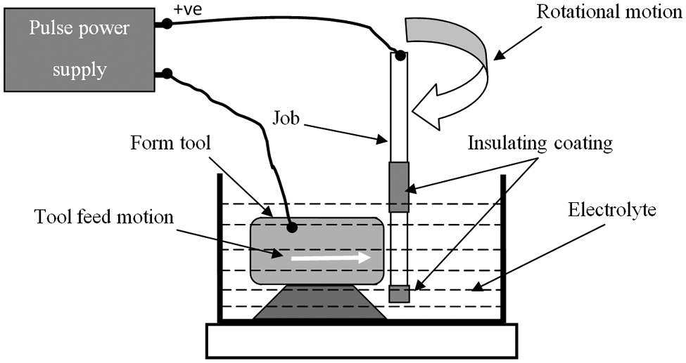
Principle of micro electrochemical form turning.
Experimental setup
A micro-ECM setup has been developed indigenously for performing wide range of noncontact type tool–based micromachining operations such as micro-ECM and micro-EDM. The outline of the setup is illustrated in Figure 2(a). It consists of computer numeric control (CNC) stages, for providing X–Y motion (with resolution of 1 µm) to the workpiece and Z motion (with resolution of 0.1 µm) to the tool, and the reverse distribution of motion is followed when machining of micro tool is performed. The tool can also be rotated about its own axis in both clockwise and anticlockwise directions. Pulse power supply is the one of the very important components of the machine. The full description of the pulse power supply has been illustrated in the following paragraph.
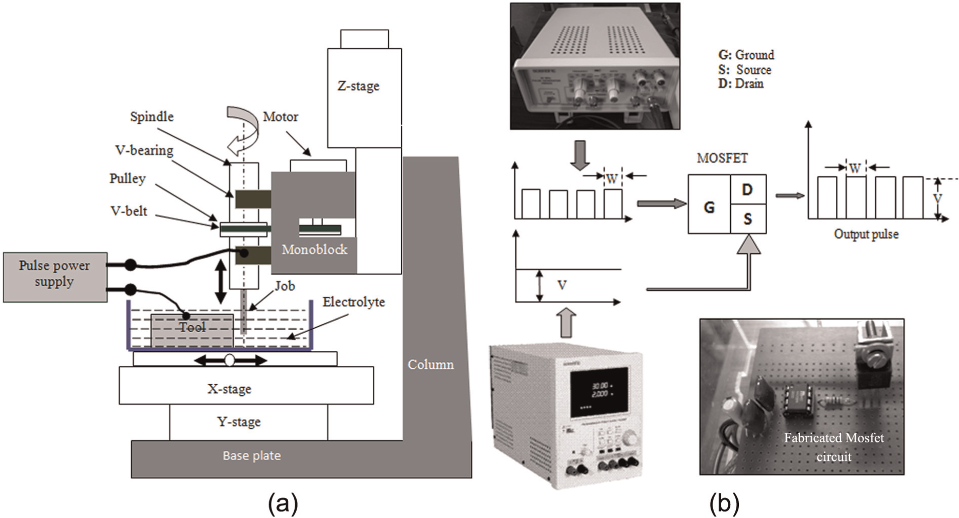
(a) Experimental setup and (b) different components of pulse power supply.
A metal oxide semiconductor field effect transistor (MOSFET)-based pulse power supply (Figure 2(b)) has been designed to handle the power requirement of the machine in different micromachining operations. The monitoring and controlling of interelectrode gap distance at a required level is one of the essential requirements to localize the electrochemical reaction. In the present system, the interelectrode gap control has been performed by measuring the gap current. A Hall current sensor is deployed for converting the gap current to the equivalent voltage and is acquired by a data acquisition card. The acquired data are processed in the software program, and accordingly, the movement action of the stage is decided. The details of experimentation for cylindrical micro tool machining have been described in the succeeding sections.
Experimentation
A high-speed steel (HSS) bar of square cross section (5 mm × 5 mm), tungsten rod of 1.5 mm diameter and KOH solution have been used as cathode, anode and electrolyte, respectively. The setup arrangement for the experimentation is shown in Figure 2(a). The experimental parameters such as machining voltage (V), pulse on time (Ton) and concentration of electrolyte (M) are chosen as variable parameters. Other parameters like frequency (kHz) of pulse power supply, rotational speed (r/min) of the anode (job), agitation of the electrolyte, electrolyte temperature and tool feed rate (1 µm/s) are maintained at the uniform level for all the experiments. The time of fabrication of micro tools with different parameter settings has been decided after conducting the pilot experiments.
In the present research framework, the microelectrodes have been fabricated by varying input parameters to observe the influence on the length cylindrical shape of the machined micro tool. The working ranges of different experimental parameters have been chosen by conducting trial experiments. Four experiments have been performed for the variation of each parameter within the pre-decided range. After machining, the obtained tool looks like a dumbbell shape toward both ends due to the diffusion layer effect. But at the middle portion of the fabricated tools, up to some length, cylindrical shape was observed. So from the lower end, unwanted portion has been removed by electrochemical dissolution process to get the cylindrical portion of micro tool. In this way, cylindrical micro tools are fabricated.
Result and discussion
After performing the experiments, scanning electron microscope (SEM) images of the fabricated tungsten micro tools have been captured. Figures 3–5 illustrate the SEM images of microelectrodes, which have been fabricated with the variation of input parameters such as pulse on time, applied voltage and concentration of electrolyte. The values of the variable experimental parameters have been indicated on the respective SEM images. Using a simple software technique, the cylindrical length of the electrodes has been measured and plotted against the respective parameters. The length of the cylindrical portion has been marked with white lines in the respective images except in Figure 3(d) because the full length of the cylindrical portion could not be captured in the SEM image.
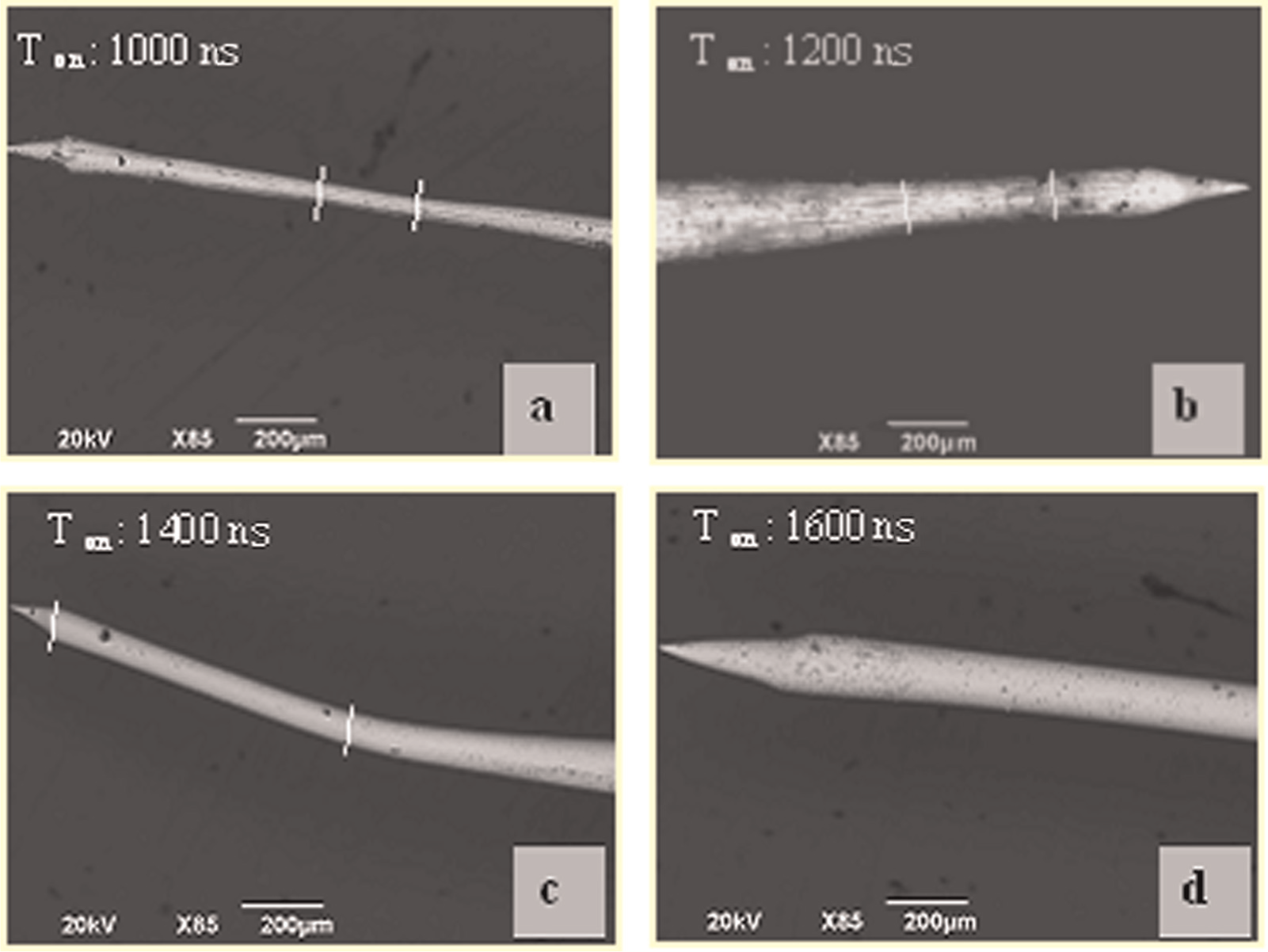
SEM images of the tungsten micro tools fabricated with variation of pulse on time, (a) 1000ns, (b) 1200ns, (c)1400ns and (d) 1600ns.
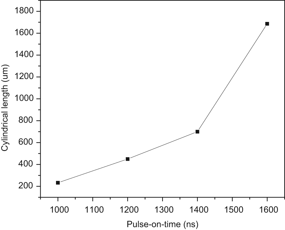
Variation of cylindrical length with the pulse on time.
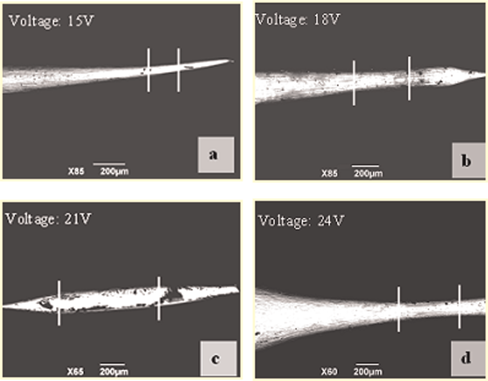
SEM images of the tungsten microelectrodes fabricated with variation of applied voltage, (a) 15V, (b) 18V, (c) 21V and (d) 24V.
Influence of pulse on time on cylindrical length of the microelectrodes
In this group of experiments, the values of constant experimental parameters are as follows: initial interelectrode gap distance of 100 µm, frequency of the pulse power supply of 500 kHz, voltage of 18 V and electrolyte concentration of 3 M. SEM images of the resulting electrodes have been captured and illustrated in Figure 3. From the plot (Figure 4), it has been observed that the length of the cylindrical portion of the fabricated microelectrode increases as the Ton increases. But with high value of Ton (>1800 ns), the spark machining starts and the surface roughness of the fabricated microelectrodes increases due to the nonuniform dissolution of the anode material, and it is difficult to control the process. The bending of the tool in Figure 3(c) is due to the mishandling, while capturing the SEM image.
The ascending nature of the graph can be explained in the following. During the pulse on time, the dual layer capacitor charges, and during pulse of time, the charged dual layer capacitor discharges, as a result of which the current flows in the interelectrode gap. As the area of the job is fixed by providing the paraffin coating, with an increase of Ton, the machining current increases and thereby the machining rate increases. At low value of Ton (1000 ns), the dual layer capacitor does not get enough time to be charged fully, which leads to irregular charging and discharging of the capacitor. This leads to the irregular surface of the microelectrode (Figure 3(a) and (b)). And at high value of Ton (>1800 ns), very high surface roughness is observed. Due to the improper flushing of electrolyte, the debris cannot be fully flushed out of the interelectrode gap, leads to spark machining. When the Ton value is set in the range of 1400–1600 ns, good cylindrical shape of the fabricated micro tools is fabricated.
Influence of machining voltage on cylindrical length of the microelectrodes
Figure 5 shows the SEM images of the tungsten microelectrodes with the variation of machining voltage. The values of the constant parameters are pulse on time of 1200 ns, frequency of 500 kHz and electrolyte concentration of 3 M. The variation of the cylindrical length with respect to the applied voltage is illustrated in Figure 6. At the machining voltage of 21 V, the maximum length of the cylindrical tool is obtained and beyond 21 V, and the length is reduced due to the spark machining in the interelectrode gap. This happens due to the high rate of formation of hydrogen bubbles in the interelectrode gap.
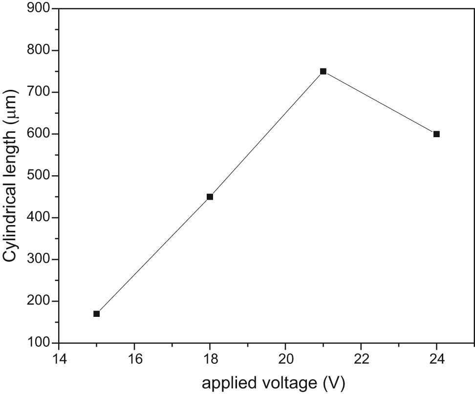
Variation of cylindrical length with the applied voltage.
The formation of neck has been observed in Figure 5(c) due to the loose bonding of the paraffin to the surface of the electrode, which indicates that the nonconductive coating neutralizes the effect of geometry in other experiments. With the increase of applied voltage, the diffusion layer effect is increased, 15 but as the job rotates at the close vicinity of the tool and due to the rigorous agitation of the electrolyte, the diffusion layer effect feds away. At low voltage (15 V) and with a Ton value of 1200 ns, the dual layer capacitor cannot charge fully. So the irregular machining takes place, which leads to low cylindrical length of the micro tool. As the applied voltage increases, with the same Ton duration, the capacitor charges fully and hence uniform machining is carried out. Because of this reason, the cylindrical length of the micro tool increases with increase of applied voltage.
Influence of concentration on cylindrical length of the microelectrodes
Figure 7 shows the SEM images of the microelectrodes, which have been fabricated with concentration variation. The values of different fixed parameters are pulse on time of 1200 ns, frequency of 500 kHz and applied voltage of 18 V. The variation of concentration of electrolyte does not show any significant role in achieving a higher cylindrical length of the fabricated microelectrodes (Figure 8).
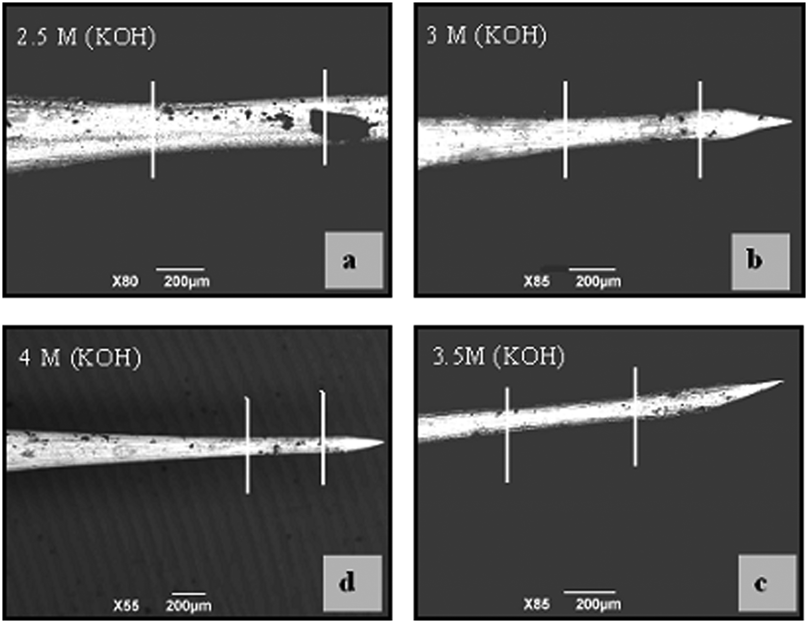
SEM images of tungsten microelectrodes fabricated with concentration variation, (a) 2.5M (KOH), (b) 3M (KOH), (c) 3.5M (KOH) and (d) 4M (KOH).
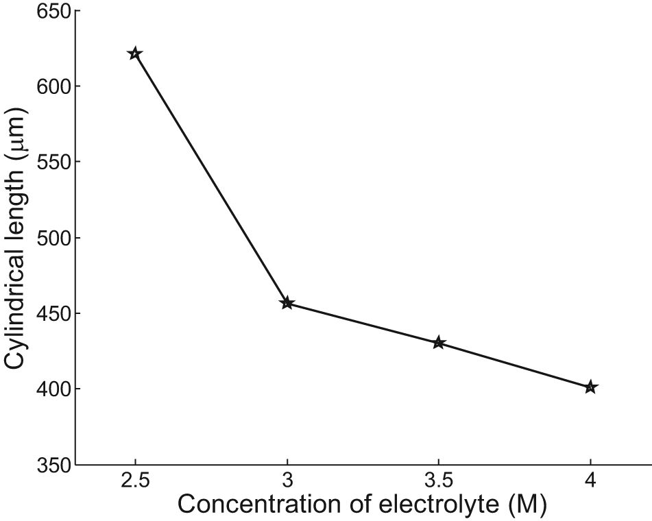
Variation of cylindrical length with concentration of electrolyte.
In the present research purview, higher cylindrical length is achieved at 2.5 M solution of KOH. As the concentration is increased, the reaction rate in the interelectrode gap is increased proportionally. The present uniform agitation of electrolyte may not be sufficient to disperse all the residues of the electrochemical reaction from the narrow interelectrode gap, and furthermore, the conductivity of the electrolyte changes due to the poor agitation rate. This leads to nonuniform reaction on the surface of the electrode, and hence, the cylindrical length is reduced with increase in concentration of electrolyte.
Summary of result and discussion
Based on the experimental results and discussions, it is observed that with the increase of Ton and the applied voltage, higher cylindrical length of the micro tools can be realized. The increase in concentration (>3 M) deteriorates the surface quality and also reduces the cylindrical length. Better surface quality is obtained by controlling the Ton as compare to other experimental parameters. Better cylindrical shape and surface finish of the fabricated micro tool can be obtained at initial interelectrode gap distance of 100 µm, frequency of the pulse power supply of 500 kHz, machining voltage of 18 V, electrolyte concentration of 3 M and pulse on time of 1400 ns. The confirmation experiments have been performed to fabricate cylindrical microelectrodes from tungsten bar of initial diameter of 1.5 mm with the optimal parameter settings, and the optical images are presented in Figure 9. In Figure 9(a), initial diameter of the tungsten bar along with the fabricated cylindrical tool is shown. The optical images in Figure 9(b)–(d) have been captured with same scale to observe the length of cylindrical shape. In Figure 9(b) and (c), the length of the cylindrical portion is similar except in Figure 9(d). The fabricated microelectrodes get dumbbell shape at both ends and cylindrical shape at the middle. The lower portion of the dumbbell is precisely dissolved electrochemically to get cylindrical length. In Figure 9(d), the smaller length is observed as more amount material is dissolved from the lower end. The time duration for machining of each electrode in Figure 9 is 15 min.
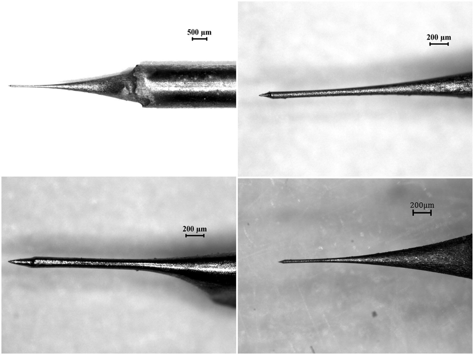
Optical images of the fabricated microelectrodes with optimum machining parameter setting (500 kHz, 18 V, 3 M and 1400 ns).
Conclusion and future scope
The fabrication of microelectrodes with an indigenously developed setup has been carried out successfully with different parameter settings to see the parametric influences on the cylindrical length of the microelectrodes, and the following conclusions are drawn.
The influence of geometry, during the fabrication of microelectrodes, can be minimized with chemically inert and electrically nonconductive coating on both ends of the anode (at the bottom end of the anode and at the interface of air and electrolyte). The influence of diffusion layer is reduced by rotating the job about its own axis in the close vicinity of the tool and by proper agitation of electrolyte. The machining of cylindrical microelectrodes of diameter of 50 µm and length more than 800 µm can be performed in a time duration of 15 min by this process from the tungsten bar of initial diameter of 1.5 mm. In the present experimental framework, cylindrical micro tool with better surface finish is obtained at the parameter settings of initial interelectrode gap distance of 100 µm, frequency of the pulse power supply of 500 kHz, voltage of 18 V, electrolyte concentration of 3 M and pulse on time of 1400 ns. The confirmation experiments are conducted at the optimal parameter settings. The sharp tip of the fabricated tools may be beneficial for many applications particularly for micro drilling operation through micro-ECM. However, the fabrication of micro tools of desire diameter and length needs further investigation.
Footnotes
Declaration of conflicting interests
The authors declare that there is no conflict of interest.
Funding
This research received no specific grant from any funding agency in the public, commercial or not-for-profit sectors.