
Abstract
This article presents the kinematics model and control simulation of a hydraulic boom. This hydraulic boom is used on the logging harvester, which is a typical forestry vehicle. The kinematics equations of the hydraulic boom and the transformation between joint variables and hydraulic cylinder variables are obtained for the control purpose. An autonomous control method is suggested for the harvesting head to capture trunks. There are two separate closed loops in the control scheme: the inner closed loop realizes the control on the hydraulic cylinders, and the outer loop plans the desired trajectory of the harvesting head to capture trunks based on the laser measurement data. An interactive real-time dynamic simulation system is developed, and the proposed control method is verified.
Introduction
Because the circumstances of forest areas are very complex and hazardous, it is very laborious to harvest standing trees by hand-operated machines and tools. In the last decade, with the development of hydraulic controls and sensor techniques, more and more logging harvesters are being used in forestry.1–3 The logging harvester is a type of heavy forestry vehicle and can complete successive tasks of felling, peeling, measuring, and bucking with human intervention, so it is very suitable for large-scale clear cutting operations in fast-growing plantations.
Logging harvesters are nowadays manually operated and require operators to control a hydraulic boom by joysticks and pedals. It is a highly nonlinear task that only experienced operators can move the harvesting head on the hydraulic boom in an accurate way. In order to alleviate the workload, there is a need for an automatically controlled hydraulic boom.
Recently, various control methods for the hydraulic boom of the logging harvester were reported. Morales et al. provided trajectory-planning algorithms and motion-control methods for a laboratory setup and a commercial version of hydraulic manipulators used in forwarder machines. Time-efficient reference trajectories of motions for logging tasks are designed. Extensive tests are done to demonstrate the performance. 4 Kovanen and Handroos presented an adaptive control which was developed for the open-loop control of a log crane. The log crane was equipped with an electrically controlled proportional directional valves and digital control system. The proposed adaptive control functions a significant reduction in vibration amplitudes. 5 Kalmari et al. used the nonlinear model predictive control for a hydraulic forestry crane that has a freely hanging tool or processing head attached. The hydraulic forestry crane can follow a predefined path while simultaneously damp the undesired oscillations of the tool. The average tracking error is between 0.02 and 0.11 m with velocities of 0.5–1.0 m/s. 6 Mettin et al. suggested the strategy of path-constrained trajectory planning and the time-independent control scheme for forestry logging machines. Experimental tests demonstrate the feasibility of the proposed methods. 7 Guo et al.8,9 calculated the forward and the inverse kinematics solutions for the hydraulic crane of a logging harvester and adopt radial basis function (RBF) neural network controller to control the movement of the hydraulic crane. La Hera et al. 10 proposed a control algorithm which was composed of a linear controller and a compensator for nonlinearities and able to accurately track a reference trajectory for the hydraulic forestry crane.
In this article, an autonomous control method is used for a logging harvester in virtual environments. Section “Mechanical structure of the logging harvester” describes the mechanical structure of the logging harvester; section “Kinematics modeling” obtains the kinematics equations of the hydraulic boom and the transformation between joint variables and hydraulic cylinder variables; section “Control design” presents the control method in particular; in section “Experiment,” experiments are carried out in the interactive real-time dynamic simulation system to illustrate the validity of the proposed control strategy; the conclusion and some ideas for further work are presented in section “Conclusion.”
Mechanical structure of the logging harvester
The mechanical structure of Beijing Forestry University (BJFU) logging harvester is shown in Figure 1.11,12 It consists of a four-wheel chassis, a hydraulic boom, a harvesting head, a hydraulic system, and an electrical control system. The hydraulic boom has four revolute joints, namely, pitch joint, slew joint, main joint, and jib joint, and one prismatic joint, namely, extension joint. The joints are driven by the pitch, slew, main, jib, and extension hydraulic cylinders. The joints of the hydraulic boom are instrumented by linear or rotation encoders. The harvesting head is freely hanging on the tip of the boom with a shackle and a rotator and consists of a couple of clipping claws, two driving rolls, two measurement rolls, a pair of delimbing knives, and a chain saw.

BJFU logging harvester.
Kinematics modeling
The kinematics analysis of the hydraulic boom is the basis of the control strategy. The forward kinematics is applied when identifying the position and pose of the harvesting head in terms of joint variables, whereas the inverse kinematics is used for the control purpose. Meanwhile, because the displacement of the hydraulic cylinders causes the desired movement of joints, the transformation between joint variables and hydraulic cylinder variables also has to be identified.
Simplified model
Some simplifications need to be done in order to keep the mathematical expressions as short as possible. First, the four-wheel chassis is supposed to be stationary during the working phase, so the coordinate frame {0} on the four-wheel chassis is considered to be the inertial frame. The hydraulic boom is simplified to four revolute joints and one prismatic joint. The coordinate frames for the hydraulic boom are shown in Figure 2.

Coordinate frames for the hydraulic boom.
In Figure 2, the coordinate frame
D-H parameters of the hydraulic boom.

Transformation between joint variables and hydraulic cylinder variables
The hydraulic boom is simplified as a multi-bar linkage mechanism in Figure 3. The transformation between joint variables and hydraulic cylinder variables can be calculated by the trigonometric approach.

Simplified multi-bar linkage mechanism of the hydraulic boom.
In Figure 3, the joint variables θ2 and d5 are equal to the variables of the slew and extension hydraulic cylinders, respectively. The transformation between the other joint variables and hydraulic cylinder variables can be calculated as follows:
Transformation between θ1 and the variable of the pitch hydraulic cylinder: In Figure 3, θ1 is the variable of joint 1, the length LAB is the variable of the pitch hydraulic cylinder, and ∠AO1X1 is constant. θ1 can be calculated by the cosine law as follows

2. Transformation between θ4 and the variable of the jib hydraulic cylinder: In Figure 3, θ4 is the variable of joint 4, the length LDE is the variable of the jib hydraulic cylinder. The cosine law can be used in the four-bar linkage mechanism GJKO4, and ∠IJG can be calculated as shown in equations (2) and (3)


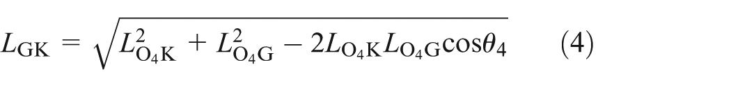
∠JGO3 can be calculated as shown in equations (4)–(6)


In Figure 3, HIJGO3 forms a five-bar linkage mechanism which can be rotated and specified in the coordinate frame as Figure 4.
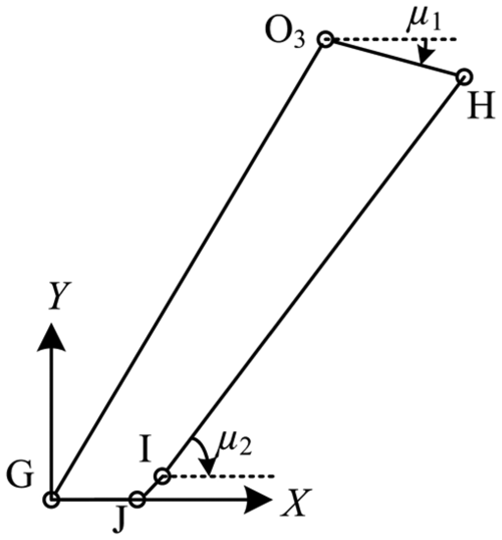
Specified five-bar linkage HIJGO3.
In Figure 4, the vector

By projecting

The angle µ1 can be calculated by solving equation (7) as follows

The symbols in equation (8) are determined as follows

In Figure 4, ∠HO3G can be calculated as follows

The relation between ∠HO3G and LDE can be calculated by the cosine law as follows

In equation (11), ∠HO3G is described by the function of θ4.
3. Transformation between θ3 and the variables of the jib and main hydraulic cylinders: In Figure 3, θ3 is the variable of joint 3 and determined by the lengths of jib hydraulic cylinders LDE and main hydraulic cylinders LCM together. ∠CO3M can be calculated as follows

∠HO3G is determined by LDE using equation (11) and ∠CO3H is constant.
The relation between ∠CO3M and LCM can be calculated by the cosine law as follows

In equation (12), ∠CO3M is described by the function of θ3.
Forward kinematics
The hydraulic boom is a highly nonlinear system, and the motion control is specified in terms of the path traveled by the harvesting head in Cartesian coordinate. Computing the position and pose of the harvesting head in Cartesian coordinate from the displacements of joints is by means of the forward kinematics. According to the D-H parameters in Table 1, the forward kinematics equation of the hydraulic boom is described by functions of five joint displacements, which are fed back from the encoders fixed in the joints.
The forward kinematics equation for the hydraulic boom can be expressed in the multiplication product of successive 4 × 4 matrices

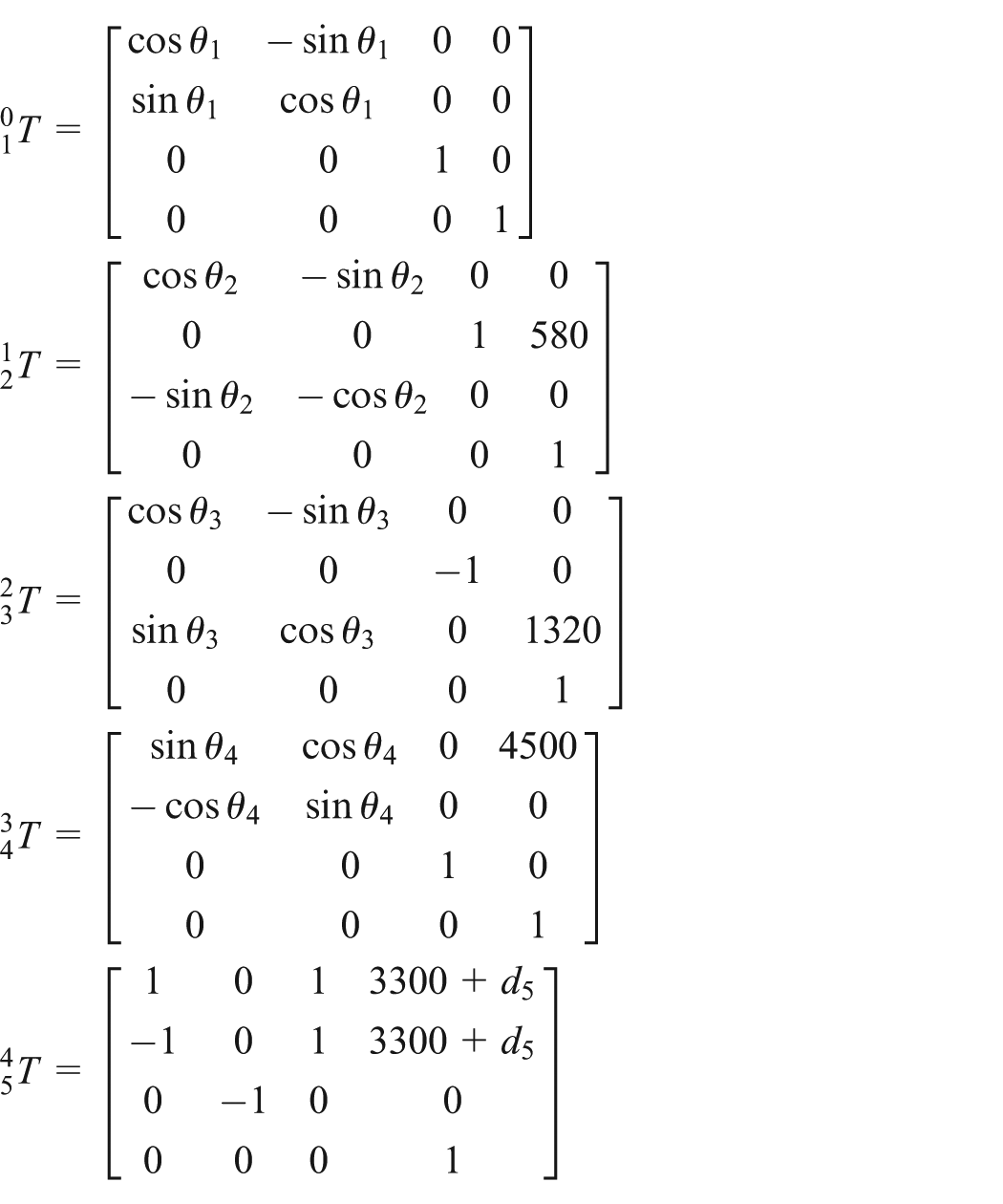
Equation (13) is the forward kinematics equation of the hydraulic boom.
Inverse kinematics
In the control strategy, the harvesting head moves with a certain velocity vector in Cartesian space, and inverse Jacobian is used to calculate every joint displacement at each control period. Supposing 3 × 1 linear velocity vector and rotational velocity vector of the harvesting head are
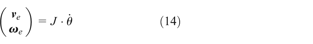
In equation (14), for J is not a square matrix, the 5 × 6 pseudo-inverse of Jacobian matrix

Equation (15) is the inverse kinematics equation of the hydraulic boom. Using equation (15), the joint velocities can be calculated at each instant during the mission.
Control design
Due to the friction of hydraulic cylinders, torsion and vibration of the long boom are hard to be estimated, and sole dynamic control for the hydraulic boom is impossible to achieve the mission. In our previous research, 16 a laser measurement system is mounted on the harvesting head to determine the relative position and pose of the trunks with respect to the harvesting head as shown in Figure 5. The estimated position and pose data are fed back to the central controller for the control strategy. In this research, the laser measurement data are used for the autonomous control of the logging harvester in virtual environments. The schematic diagram of the autonomous control is shown in Figure 6.
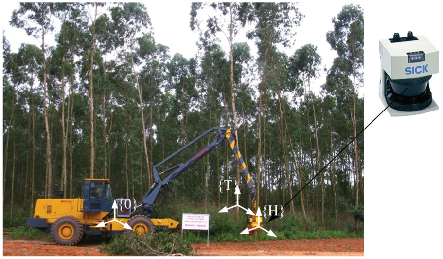
Implement on the logging harvester.

Schematic diagram of the autonomous control.
There are two separate closed loops in the schematic control. The inner closed loop realizes the hydraulic cylinders control by exploiting the joint angular feedback by a discrete proportional–integral–derivative (PID) controller. 7 The outer loop provides the desired trajectory and for the harvesting head to capture trunks based on the laser measurement data in the following steps:
Step 1. The logging harvester moves to a point by the operator, where the target trees are in the reachable area of the hydraulic boom.
Step 2. Collecting the point cloud for the surrounding trunks by the laser measurement system and extracting the trunks feature. The position vector
Step 3. Using the forward kinematics equation (13) and current joint angles θ = (θ1, θ2, θ3, θ4, d5)T, the transformation matrix
Step 4. Calculating the transformation matrix
Step 5. Using the center of the target trunk TO as the end point of the path planning. Calculating the straight line distance

Step 6. Calculating the desired Cartesian velocities vector of the harvesting head

In equation (17), vel is the velocity quantity of the harvesting head and set by the user and dt is the time of one control period. Using the pseudo-inverse of Jacobian matrix

Step 7. Considering the maxim joint velocity is

Meanwhile, if any joint velocity

In equation (20),
Step 8. Using equation (19) or (20), the desired joint angles at the end of each control period can be calculated as
If joints or hydraulic cylinders approaching or exceed the motion range limitation, the chassis of the logging harvester will move to a new point next to the target trees by the operator.
Step 9. If the difference vector
Experiment
Interactive real-time dynamic simulation system
Because it is dangerous to test the control method on the real logging harvester in the initial phase, an interactive real-time dynamic simulation system is developed to verify and optimize the proposed autonomous control method. This virtual simulation system is developed by Open Scene Graph (OSG) as shown in Figure 7.

Interactive real-time dynamic simulation system.
The system is mainly composed of trajectory control module, joint control module, logging harvester module, laser module, and tree module. The trajectory control module plans the desired motions of the hydraulic boom and chassis according to the command. The joint control module realizes the control of each hydraulic cylinder. The logging harvester module is consisted of virtual models of chassis, hydraulic boom, and harvesting head. The tree module can display virtual graphics of target trees. The laser model can execute the real and virtual laser measurements for target trunks.
Verification of the control method
During the experiment, the parameters for the motion of the hydraulic boom are set as follows:
Motion range limitation of joints.

Motion range limitation of hydraulic cylinders.

The position data of the virtual trunks are obtained from the previous laser measurement experiment in the aspen forest. 16 The position and Euler angle vector of the virtual trunk respective to the harvesting head are calculated in every control period.
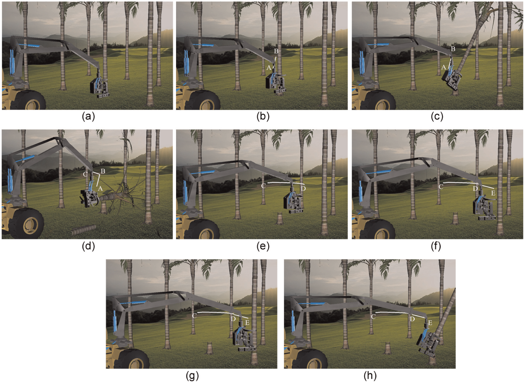
The mission of successively capturing and felling virtual trunks is used to validate the control method. The harvesting head traces planned straight or circular paths when it transfers between trunks.
The white lines in Figure 8(a)–(h) are the motion trace of the harvesting head. In Figure 8(a), the logging harvester moves to a specified point, where the target trees are in the reachable area of the hydraulic boom. In Figure 8(b), the harvesting head moves autonomously along the white line from point A to point B by the control method and captures the virtual trunk. In Figure 8(c), the harvesting head fells the trunk. In Figure 8(d), the harvesting head drags the virtual trunk from point B to point C and executes delimbing and bucking tasks. In Figure 8(e) and (f), the harvesting head moves from point C along the planned straight and circular trajectories and reaches point D next to another virtual trunk. In Figure 8(g), the harvesting head moves autonomously along the white line from point D to point E by the control method and captures the trunk. In Figure 8(h), the harvesting head fells the trunk and executes the subsequent tasks.
Experiment in the real-time dynamic simulation system.
During the above mission, the pitch hydraulic cylinder keeps still, so that the angle of the joint 1 is fixed. The displacements of the 2nd–5th joints are shown in Figures 9–12.

Displacement of the second joint.

Displacement of the third joint.
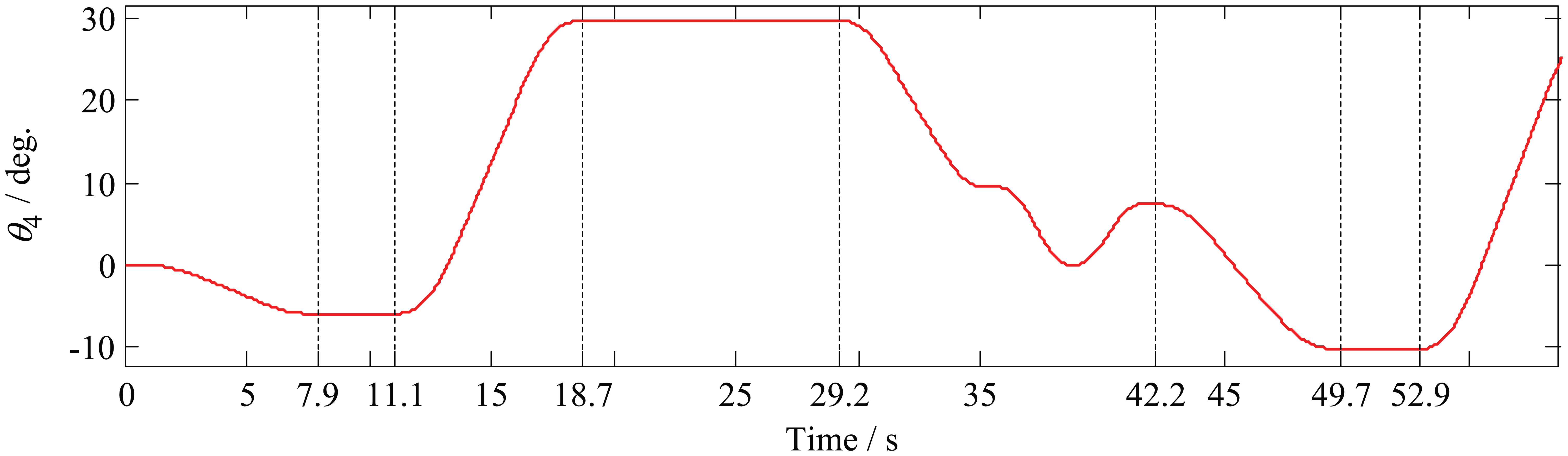
Displacement of the fourth joint.
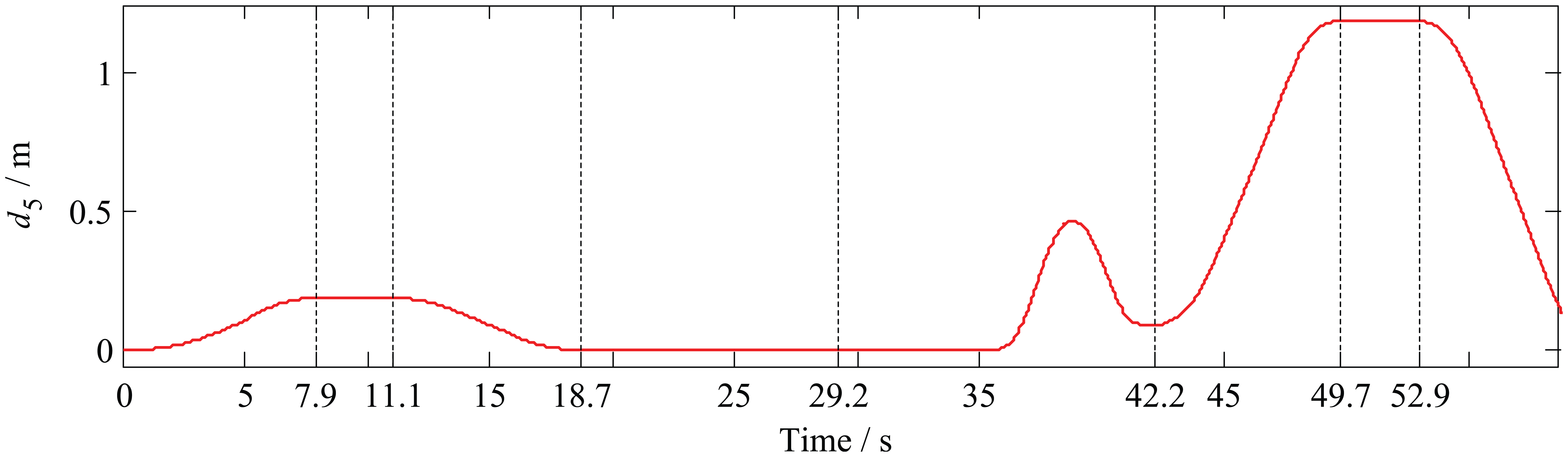
Displacement of the fifth joint.
The displacements of the slew and extension hydraulic cylinders are equal to θ2 and d5, respectively. The displacements of the main and jib hydraulic cylinders are shown in Figures 13 and 14.
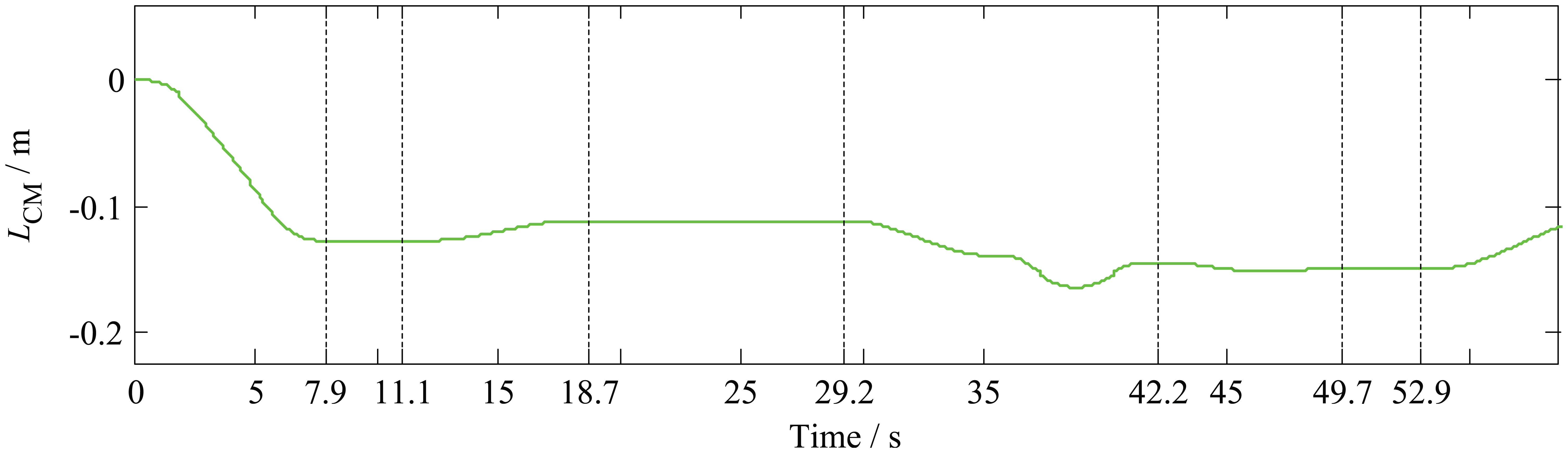
Displacement of the main hydraulic cylinder.

Displacement of the jib hydraulic cylinder.
In Figures 9–14, from 0 to 7.9 s, the autonomous control method is executed for capturing the trunk as shown in Figure 8(b); from 7.9 to 11.1 s, the hydraulic boom keeps still, and the harvesting head fells the trunk as shown in Figure 8(c); from 11.1 to 18.7 s, the harvesting head drags the trunk from point B to point C as shown in Figure 8(d); from 18.7 to 29.2 s, the hydraulic boom keeps still, and the harvesting head executes delimbing and bucking tasks; from 29.2 to 42.2 s, the harvesting head moves to point D next to another trunk as shown in Figure 8(e) and (f); from 42.2 to 49.7 s, the autonomous control method is executed for capturing the trunk again as shown in Figure 8(h); and from 49.7 s, the harvesting head fells the trunk and executes subsequent tasks as shown in Figure 8(g).
The maximum values of the 2nd–5th joint velocities during the experiment are given in Table 4.
Maximum values of joint velocities.

All of the joints do not exceed their limits, and hydraulic cylinders work smoothly. From the above simulation results, it is concluded that the proposed control method can achieve a relatively favorable control performance.
Conclusion
In this article, in order to further improve the automation level of a logging harvester, an autonomous control method is used for the harvesting head to capture trunks. The forward and inverse kinematics equations of the hydraulic boom are calculated based on the D-H parameters. Meanwhile, the transformation between the joint variables and hydraulic cylinder variables are also identified. During the procedure of capturing trunks, the desired trajectory of the hydraulic boom is planned in Cartesian space based on the laser measurement data. The proposed approach is verified in an interactive real-time dynamic simulation system based on OSG.
The proposed autonomous control method will be tested on the real logging harvester in the next step. The burden of the operator can be lightened by increasing the automation level of the logging harvester. The interactive real-time dynamic simulation system can also be used for the operator training and new product tests in the future.
Footnotes
Academic Editor: Pietro Scandura
Declaration of conflicting interests
The author(s) declared no potential conflicts of interest with respect to the research, authorship, and/or publication of this article.
Funding
This study is financially supported by the Fundamental Research Funds for the Central Universities (no. YX2013-13), China Postdoctoral Science Foundation (nos 2014T70040 and 2011M500009), Doctoral Program of Higher Education of China (no. 20120014120015), and National Nature Science Foundation of China (no. 31300596).