
Abstract
Undesired movements of the spray boom are the main causes of an irregular spray distribution of agro-chemicals; the rolling motion of the boom is particularly significant. This article presents an adaptive robust control scheme for the active pendulum boom suspension to control the roll motion of the spray boom with electro-hydraulic actuators. A hybrid model which combines an analytical modeling procedure with identification techniques of a 28-m spray boom with active suspension is developed. Then, a model-based adaptive robust controller is designed for the precision motion control of the boom, with consideration of the nonlinearities such as uncompensated friction and disturbances and the effect of parameter variations coming from the various hydraulic parameters. A sprayer boom suspension system test rig combined with a 6-degree-of-freedom motion simulator is specifically designed and developed to verify the control scheme; the proposed controller and proportional–integral controller have been implemented on a laboratory experiment. Experimental results reveal that the proposed controller can guarantee a prescribed transient performance and tracking accuracy in the presence of both parametric uncertainties and uncertain nonlinearities; it also means that the model-based adaptive robust control scheme is effective in roll movement control of the spray boom, and then the uniformity of spray distribution can be guaranteed.
Introduction
The boom sprayer has the characteristics of high spray pressure, uniform atomization, wide spray width, and high working efficiency. It is an ideal field plant protection machine, widely used to supply the plants with agro-chemicals. Spray vehicles roll as it runs on the undulating farmland is the main reason caused by the undesired boom movement, especially when the rolling of the boom creates local under-applications and over-application of spray liquid.1–5 Related research shows that the boom rolling is responsible for variations in spray deposit uniformity ranging from 0% to 1000% (100% is ideal).6–8 So this article concentrates on boom roll, the effect on spray distribution of which is shown in Figure 1. The rolling movement of the boom causes the nozzle height above the target to be different. The area covered by the spray nozzles changed, and the uneven distribution and leakage zone generated along the boom length. 9 In order to reduce the unevenness in spray deposit, many boom sprayers are equipped with suspension systems to suppress the undesired roll movement. 10 The traditional passive boom suspensions can reduce the effect of roll on the spray distribution pattern using gravity. 11 However, it cannot adjust the boom to low-frequency undulations in ground slope on hilly fields, resulting in an uneven spray distribution pattern, what’s worse is that the tips of the boom touch the ground, causing serious damage to the crop and the sprayer.12,13 Nowadays, the width of the spray boom increased dramatically because of long boom widths, a heavy moment of inertia, and various disturbances; the roll movement control of spray booms has become very challenging to researchers. 14

Movement of the spray boom and the droplet distribution.
Electro-hydraulic servo system occupies an important position in modern agricultural equipment with its small power ratio and large force–torque output capability.15,16 Though the active suspensions implemented with conventional controllers such as P, PI, and H∞ control, linear quadratic Gaussian technique with loop transfer recovery (LQG-LTR) theory has been developed for application, and they could not cope with the unknown disturbances effectively as the work speed increases rapidly.17–21 Because various forms of disturbance, uncertainty, and nonlinearity exist in the hydraulic boom suspension system, the traditional controllers find it difficult to guarantee the increasingly strict performance requirements under the condition of high-speed operation. The nonlinear behavior of electro-hydraulic servo system (such as the nonlinear flow characteristics of servo valve) and modeling uncertainty (such as unmodeled nonlinearity and uncertain parameters) make the design of high-performance controller much more complicated. 22 Based on these reasons, modern control methods, such as neural network control algorithm, fuzzy algorithm, and adaptive control algorithm, have recently become a research hotspot, which is used to improve the control accuracy and robustness of servo system. 23 Generally, in dealing with the uncertain parameters and unmodeled disturbances of control system, many advanced nonlinear control strategies have been proposed, such as feedback linearization control, 24 nonlinear adaptive controls and its variants,25,26 and the robust integral of the sign of the error (RISE)-based adaptive control. 27 However, there are very limited research works on the practical application of nonlinear adaptive control method to control the undesired movement of a spray boom directly.28,29
In this article, an adaptive robust controller is proposed for the active pendulum boom suspension with electro-hydraulic actuator. First, an analytical model of an active pendulum suspension first derived with parameter obtained from identification techniques is developed. Then, a model-based adaptive robust controller is proposed for the active suspension driven by a hydraulic cylinder by referring to adaptive backstepping design in the literature,30–33 with consideration of the nonlinearity, modeling uncertainty in practice. To test the proposed nonlinear adaptive robust control strategy, a hydraulic servo system for an active pendulum suspension of the 28-m crop sprayer has been designed, a large number of contrast tests have been carried out, the high-performance nature of the proposed controller for the roll movement control was verified, and the external disturbance is generated by a 6-degree-of-freedom (DOF) platform in the process of testing. Theoretical analysis and experimental results also show that the controller can ensure the transient performance and steady-state tracking precision of the system when the parameters are uncertain. Compared to the traditional proportional–integral (PI) controller, the proposed controller achieves a larger reduction in tracking errors. It also means that the model-based adaptive robust control scheme is effective in roll movement control of the spray boom; therefore, the uniformity of spray distribution can be guaranteed.
This article is organized as follows. Section “Problem formulation and dynamic models of the suspension” shows the problem formulation and modeling of the suspension. The model-based adaptive robust controller design procedure and its main theoretical results are presented in section “Adaptive robust controller design.” Experimental results are obtained in section “Comparative experimental results.” Some conclusions can be found in section “Conclusion.”
Problem formulation and dynamic models of the suspension
Problem formulation
A boom suspension should drive the boom to follow low-frequency ground undulations to remain parallel to the ground. As shown in Figure 2, the structure of the pendulum boom suspension is composed of pendulum rod, hydraulic actuator, center frame, carrier frame, coil spring, and lateral shock absorber. The support frame is used to bear the gravity of the boom system and inertia load. The left and right arms of the spray boom are connected to the center frame by the revolute joints. The boom is suspended from the support frame by the pendulum rod OP and point P is the mass center of the spray boom. The pendulum rod is connected to the support frame at rotation O through a revolute joint. For passive suspension, the boom will only pivot about O, but under the action of a hydraulic cylinder which changes in length in response to signals from the control system, the boom will also revolve around point P. It should be noted that the roll movement at low frequencies should be controlled by a hydraulic actuator while the vibrations at high frequencies are suppressed by the passive suspension.

Spray boom and suspension device.
Mathematical model of suspension
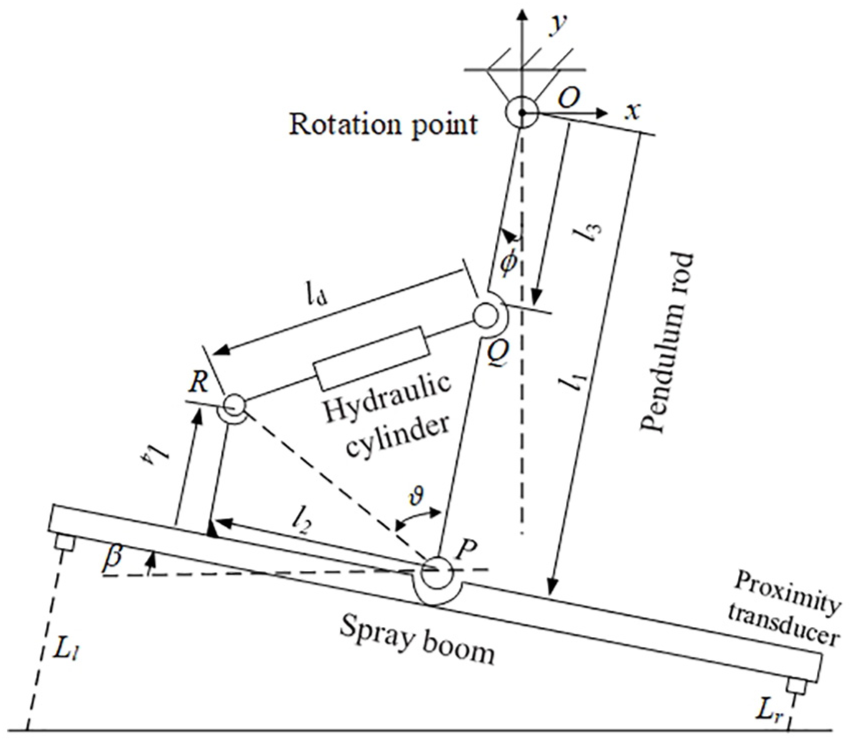
A sketch of the active pendulum suspension with all the necessary parameters is shown in Figure 3. The two proximity sensors are mounted on the left and right sides of the boom to monitor the distance from the target. This height information is processed by the control system which calculates the inclination angle β of the boom to target position, and then supplies the appropriate signal to control hydraulic cylinder movement, driving it to extend or retract adjust boom attitude. Inclination angle β of the boom to target position can be obtained by

where Lr represents the heights of the right transducers to the ground, Ll represents the heights of the left transducers to the ground, and DL represents the installation distance of two transducers.
Geometric description of the active pendulum suspension.
When the spray boom is in the horizontal position, and the pendulum rod OP is in the vertical position, define the initial length of the cylinder as ld0, and the displacement yd of the piston rod can be given by

The vectors in Figure 3 by which the closed kinematic chain can be described as 34
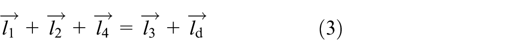
in which the vectors
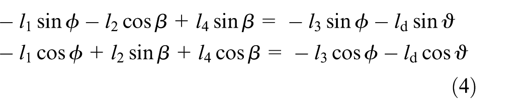
in which ϕ represents the inclination of pendulum link OP to vertical, β is the inclination of the boom to target position (the special situation is horizontal), and ϑ is the inclination angle between pendulum rod OP and line PR. By eliminating the term with ϑ in equation (4), ϕ can be written as a function of β and ld as

where a1 and a2 are the linearization constants. Justification for the linearization can be found in the fact that the maximum roll angle of the boom to target does not exceed 6°, resulting in a very small variation of the coefficients, so these coefficients can be approximately constant.
Using piston displacement ld and inclination of the boom to target position β as generalized coordinates, the equation of motion of the boom suspension can be determined by applying Lagrange’s modeling method for the coordinate (ld, β), which can be stated in the form 34


where TL represents the total kinetic energy, VL represents the potential energy, DL represents the dissipation function, and Qld and Qβ are the generalized forces.
The generalized forces Qld related to coordinate ld, and Qβ related to coordinate β, are


where F is the force exerted by the actuator.
The total kinetic energy TL of the system is

where I and M are the moment of inertia and the mass of the boom, respectively.
The potential energy VL of the system is

where
The dissipation function of energy of the suspension DL is

where C represents the equivalent rotational damping coefficient of the suspension about pivot point O.
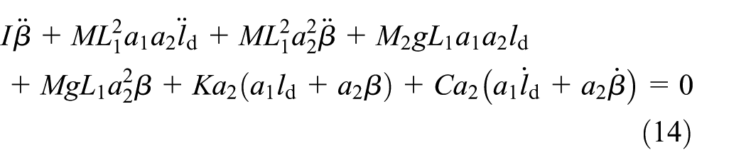
Application of equations (6) and (7) with equations (8)–(12) gives the equation of motion below

Usually, the position control of a hydraulic cylinder is achieved by controlling the flow of the hydraulic oil to the cylinder body. When an electro-hydraulic cylinder is used, manipulation of the voltage to the servo valve again imposes the position of the piston rod. For this purpose, the transfer function between actuator displacement ld and rotation

in which s is the Laplace variable. The driving force of the hydraulic cylinder can be calculated according to equation (13). But it is not necessary for the position servo control of the sprayer.
It can be seen from equation (14) that the suspension system can be simplified to a second-order system. Therefore, the following model structure is put forward

in which c2, c1, c0, b1, and b0 are the parameters which need to be determined.
Identification of suspension parameters
Identification of a 28-m boom of 992.6 kg with a moment of inertia of around 32,700 kg·m2 causes a problem. Since the actuator is not powerful enough to excite the high frequencies, measurement noise also entered the frequency response function beyond the natural frequency of the suspension so that the parameters could not be identified accurately.17,18 To solve this problem, a dynamic model of boom suspension is built in detail using ADAMS software, where the inertial coordinate system is OXYZ, as shown in Figure 4. The left and right arms of the boom are modeled as flexible bodies. The main parameters are measured by a laboratory test, as shown in Table 1.

Dynamic model for spray boom and suspension.
Parameters of suspension.

For verifying the accuracy of the model parameters, a signal generator is used to provide sinusoidal voltage command signal to servo valve at discrete frequencies ranging from 0.01 to 0.2 Hz with an amplitude of 0.3 V, and measuring the displacement of the hydraulic cylinder and rolling angle of the boom. Then, the simulation parameters of the dynamic model of suspension are calibrated by the test data, and the final accuracy of the model can be reached at 98.6%.
In the ADAMS dynamic simulation platform, a sine sweep signal is used as input of the cylinder, imposing a rolling motion of the boom, and the sweep range is set to 0.01–10 Hz, the amplitude is set to 10 mm, and then the rolling angle of the boom was measured through dynamic simulation. The parameters c0 = 174.2, c1 = 67.29, c2 = –0.0058, b0 = 1.993, and b1 = 0.834 are identified by the nonlinear least-squares frequency domain identification method using MATLAB, and the identification accuracy is 97.4%; the amplitude–frequency characteristic curves obtained from the test data and the identification model are shown in Figure 5.

Comparison of Bode plot for experiment and model fitting.
Nonlinear model of the hydraulic servo system
The active suspension of the spray boom is essentially a hydraulic servo device. Its power actuating mechanism is a double-rod hydraulic cylinder, whose inertia load position is controlled by a servo valve. The schematic diagram of the electro-hydraulic servo system is shown in Figure 6.

Schematic diagram of the hydraulic servo system.
The dynamics of the inertia load can be described by 35

where y and m represent the displacement and the mass of the load, respectively; PL = P1−P2 is the load pressure, in which P1 and P2 are the pressures inside the two chambers of the cylinder; A is the efficient ram area; B represents the combined viscous coefficient of the modeled damping friction; Af and Sf represent the approximated nonlinear Coulomb friction, in which Af is the amplitude and Sf is a known continuous shape function, and the subscript f represents the external unmolded disturbance. Besides, in Figure 6, Ps is the supply pressure of the hydraulic station and Pr is the return pressure.19,33
The PL dynamics can be written as 35
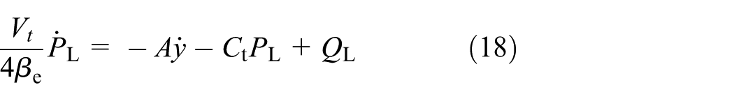
where Vt is the total control volume of the two actuator chambers; βe is the effective oil bulk modulus in the cylinder chambers; Ct is the coefficient of the internal leakage of the cylinder due to pressure; and QL = (Q1 + Q2)/2 represents the load flowrate, in which Q1 is the supplied flowrate to the forward chamber and Q2 is the return flowrate of the return chamber. QL is related to the spool valve displacement of the servo valve xv by 35

where

in which Cd is the discharge coefficient, w is the spool valve area gradient, and ρ is the density of the oil.
The relationship between the servo valve opening xv and the control input voltage u can be approximated as xv = ki·u, where ki is the positive gain of the servo valve dynamics. Therefore, equation (19) can be transformed to 35

where kt = kq·ki is the total flowrate gain with respect to the control input u.
Define the state variables as x = [x1, x2, x3]T = [y,

where Bm = B/m, Afm = Af/m, d(t) = f/m, and

here, the model of suspension and the hydraulic system have been established. In the next section, a model compensation control strategy is proposed for precision motion control of electro-hydraulic servo systems for the boom suspension.
Adaptive robust controller design
In this article, we mainly consider the uncertainties due to the external disturbances, leakages, the unknown viscous coefficient of damping friction, and Coulomb friction.
It is necessary to linearize the state-space equation (22) by a set of unknown parameters in order to improve the performance using the parameter adaptation to reduce the parametric uncertainties. The unknown parameter set is defined as θ = [θ1, θ2, θ3, θ4], where θ1 = Bm, θ2 = Afm, θ3 = dn, and θ4 = Ct. Hence, the state-space equation can be formulated as

where

here, dn represents the nominal values of d(t), and
Before the desired model compensation adaptive robust controller design, the following practical assumptions are made.
Assumption 1
The extent of parametric uncertainties is known, that is

where

where δd is the known positive constant.
Assumption 2
The desired position x1d(t) ∈C3 and all the signals are continuous and bounded.
Projection mapping and parameter adaptation
Let

where i = 1, …, 4. A parameter adaptation law is given by

where


Controller design
The controller design is based on the backstepping design approach 27 and the adaptive robust control approach proposed by Yao and colleagues,36–39 since the design model (equation (22)) contains unmatched uncertainties:
Step 1. In the first step of the backstepping process, output tracking errors z1 and z2 are defined as follows


where k1 is a positive feedback gain. Differentiating z2 in equation (32) and noting equation (24)

The state-space variable x3 can be considered as a virtual control input of the system, and the design of the virtual control method α2 is shown below

where α2 a acts as an adjustable model-based control law through online parameter adaptation given by equation (28); α2s is a robust control law that consists of two terms, where α2s1 is the nominal stabilizing proportional feedback term and α2s2 is the nonlinear robust control law to suppress the unmolded disturbance; and k2s1 and k2s2 are the positive feedback gains which will be specified later.
Let z3 = x3−α2 denote the input discrepancy, and substituting equation (34) into equation (33), we have

and
The robust control law, α2s2, can be designed according to equation (35), and the following stabilization conditions are satisfied

where ε2 is a positive design parameter, and h2 is defined as follows

where θM = θmax−θmin, then the robust term α2s2 can be designed as
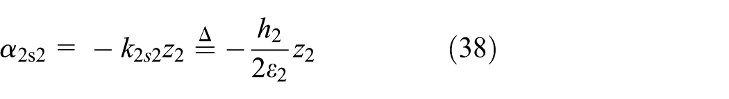
where k2s can be thought as a positive feedback gain, and it can be ensured that α2s2 satisfies the aforementioned conditions of calming.
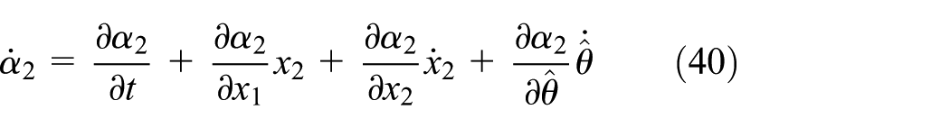
Step 2. The second step is to synthesize a control law that converges z3 to zero or a small value to ensure the transient performance of the controller. According to equation (24), the derivative of z3 can be pushed out

where
We decompose

where
Similar to the design of

where k3s1 is a positive constant feedback gain.
Substituting equation (42) into equation (39), the dynamic of z3 changes
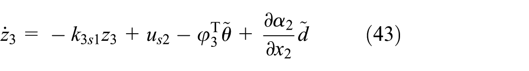
where
Similar to equations (36) and (37), us2 is easy to ensure the following stabilized conditions

where

The robust control law,
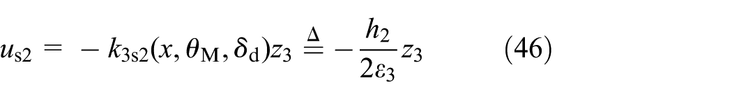
where k3s2 can be thought as a positive feedback gain, and it can be ensured that us2 satisfies the conditions (equation (44)).
Main results
Let the parameter estimates be updated by the projection-type adaptation law (equation (28)) for parametric uncertainties. The adaptation function τ is chosen as

and the feedback gains k1, k2s1, and k3s1 are chosen large enough such that the matrix defined below is positive definite

then, the proposed control law (equation (42)) guarantees the following:
A. In general, the control input and all internal signals are bounded. Define a positive semi-definite (p.s.d.) function V3(t) as

which is upper bounded as

where μ = 2λmin(
B. After a finite time t0, in the presence of parametric uncertainties such as
Proof
See Appendix 1.
Overall, the design methodology of the proposed adaptive robust controller is shown in Figure 7. The inclination angle β of the boom to the target can be obtained by two height sensors mounted on both ends of the boom in real time. Because the boom should be parallel to the target, the desired roll angle βd of the boom is equal to −β. According to equations (2) and (16), the desired motion trajectory yd = x1d(t) of the cylinder can be calculated with the desired roll angle βd. Therefore, the objective of the controller design can be simplified to synthesize a bounded control input u such that the output y = x1 tracks yd = x1d(t) as closely as possible despite various model uncertainties.

Design methodology of the proposed adaptive robust controller.
Comparative experimental results
Experimental setup
To verify the effectiveness of the proposed model-based adaptive robust controller, a test rig of sprayed boom suspension system has been set up which is shown in Figure 8. The test bench consists of a 6-DOF motion simulator, whose three-translation amplitude is 0.4 m and three-rotation amplitude is 10°, frequency range is 0.01–35 Hz with a mass of 2000 kg on the platform, a 28-m spray boom and its pendulum suspension, an electro-hydraulic position servo system, a hydraulic oil source, and real-time control system. Then, the proposed controller and PI controller are implemented on the test rig to verify the effectiveness in roll movement control of the spray boom.

Experimental platform of active boom suspension.
A boom suspension should drive the boom to follow the low-frequency component of the undulating and sloping ground. 12 If, for example, the boom is to follow field undulations of wavelengths greater than 40 m, at a faster speed of 4 m/s, then the performance of an active suspension can be determined, that is, driving the boom follows the ground fluctuation below the specified frequency of 0.1 Hz.
Since the rotation of the spray boom ranges from −6° to 6°, according to the geometric dimension of the suspension, the motion range of the cylinder from −81 to 81 mm is calculated. The maximum load (8697 N) of the cylinder is calculated by the dynamic simulation of the sprayed boom suspension in ADAMS, then a double-rod hydraulic cylinder with the efficient ram area of Ap = 904.78 mm2 and the stroke of ±100 mm is selected, whose supply pressure is 10 MPa.
Figure 9 shows the control system of the spay boom, the hydraulic system including a double-rod hydraulic cylinder, a magneto strictive displacement sensor (MTS RHM0200MD60V01 whose accuracy class is ±2.5 μm), two laser displacement sensors (Bonner LTF12UC2LDQ; its repeatable precision is ±1 mm), two pressure sensors (MEAS US175-C00002- 200BG; its repeatable precision is ±1 bar), a servo valve (Moog G761-3003), a hydraulic supply, and a monitoring and control system. The main control computer is Advantech industrial control computer (IPC-610L) that is equipped with one A/D card (Advantech PCI-1716) and one D/A card (Advantech PCI-1723). The monitoring procedure is developed with LabWindows/CVI (National Instruments), and the real-time control procedure is developed by Visual Studio (Microsoft Corporation) and RTX (IntervalZero). The sampling time is 0.5 ms.

Schematic diagram of hydraulic servo control system.
Comparative experimental results
To verify the effectiveness of the proposed control scheme, the proposed model-based adaptive robust controller is compared with the PI controller.
Adaptive robust controller
This is the model-based adaptive robust controller proposed in this article. The hydraulic system parameters are as follows: Vt = 7.96 × 10⁻⁵ m3, Ps = 10 MPa, and Pr = 0.08 MPa. The estimated flow gains are kt = 1.18e−8
PI controller
This is the proportional–integral controller. The controller gains kp = 1500 and ki = 500 are obtained based on tracking errors and repeated attempts carefully.
Some performance indices are used to assess the quality of the control algorithm: the maximal value of tracking error Me, the average value of tracking error μ, and the standard deviation value of the tracking error σ, which are defined in the study of Bu and Yao. 39
Test condition 1: sinusoidal perturbation test
The goal of the controller design is to keep the spray boom that is mounted on the chassis balance under various disturbances. So, the two controllers are first tested for a sinusoidal disturbance that represents the rolling of the spray vehicle. Sinusoidal trajectory of R1d(t) = 3sin(0.2πt)° is output by the 6-DOF motion simulator. In this test, the roll angle of the boom to target position for the two compared controllers is shown in Figure 10, and their performance indices during the last two cycles are collected in Table 2. Under the condition of non-active control, only the passive suspension plays the role of vibration isolation, and the roll angle of the boom in the time domain is shown in Figure 11. The maximum value of the steady-state tracking error of adaptive robust control proposed in this article is 0.176° and the PI controller is about 0.488°. Under uncontrolled conditions, the amplitude of the angle of the spray boom is 3.21°, and the passive boom suspension is almost ineffective for low-frequency disturbances.

Roll angle of the boom to target position for the two controllers.
Performance indices during the last two cycles for test condition 1.


Roll angle of the boom to target position for passive suspension.
The results show that the proposed model-based adaptive robust controller achieves better tracking performance due to its adaptive compensation and the regressor depends on the actual states and parameter estimates, while the PI controller just has some robustness against the modeling uncertainties and its tracking errors are much larger than the model-based adaptive robust controller. Furthermore, the function of the feedback gains in the model-based adaptive robust controller is weaker than that of PI controller but achieved better tracking performance with the help of the model compensation and parameter adaptation.
The performance indices are shown in Table 2; it can be seen that model-based adaptive robust controller has better performance than PI in all performance indices, which can verify the effectiveness of the utilized model-based compensation and parameter adaptation.
The parameter estimation of the adaptive robust controller is shown in Figure 12. The tracking error is larger at the beginning, and the tracking error gradually decreases with the process of the adaptive parameter, and then it enters the steady state.
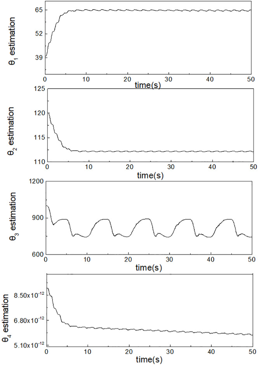
Parameter estimation of the adaptive robust controller.
Test condition 2: trajectory tracking experiment
The aim of the active suspension is to keep the boom parallel to the slope of the ground or the crop canopy under it. Therefore, it is necessary to test the tracking performance of the controller.
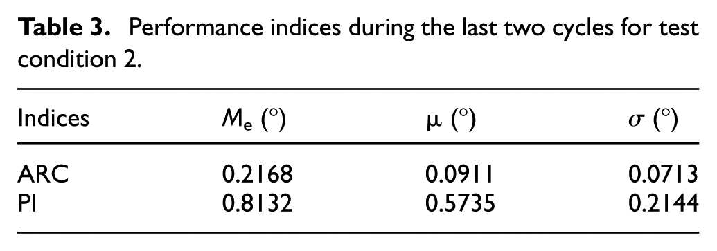
To further test the trajectory tracking performance, a trajectory β1d(t) = 3arctan(sin0·4πt)·(1−exp(−t))° is applied. The performance indices of the two controllers are shown in Table 3. The comparative tracking errors of the two controllers can be found in Figure 13. By comparing the performance indices of the adaptive robust controller and the PI controller, the proposed adaptive robust controller outperforms the PI controller again in terms of transient and final tracking performance.
Performance indices during the last two cycles for test condition 2.
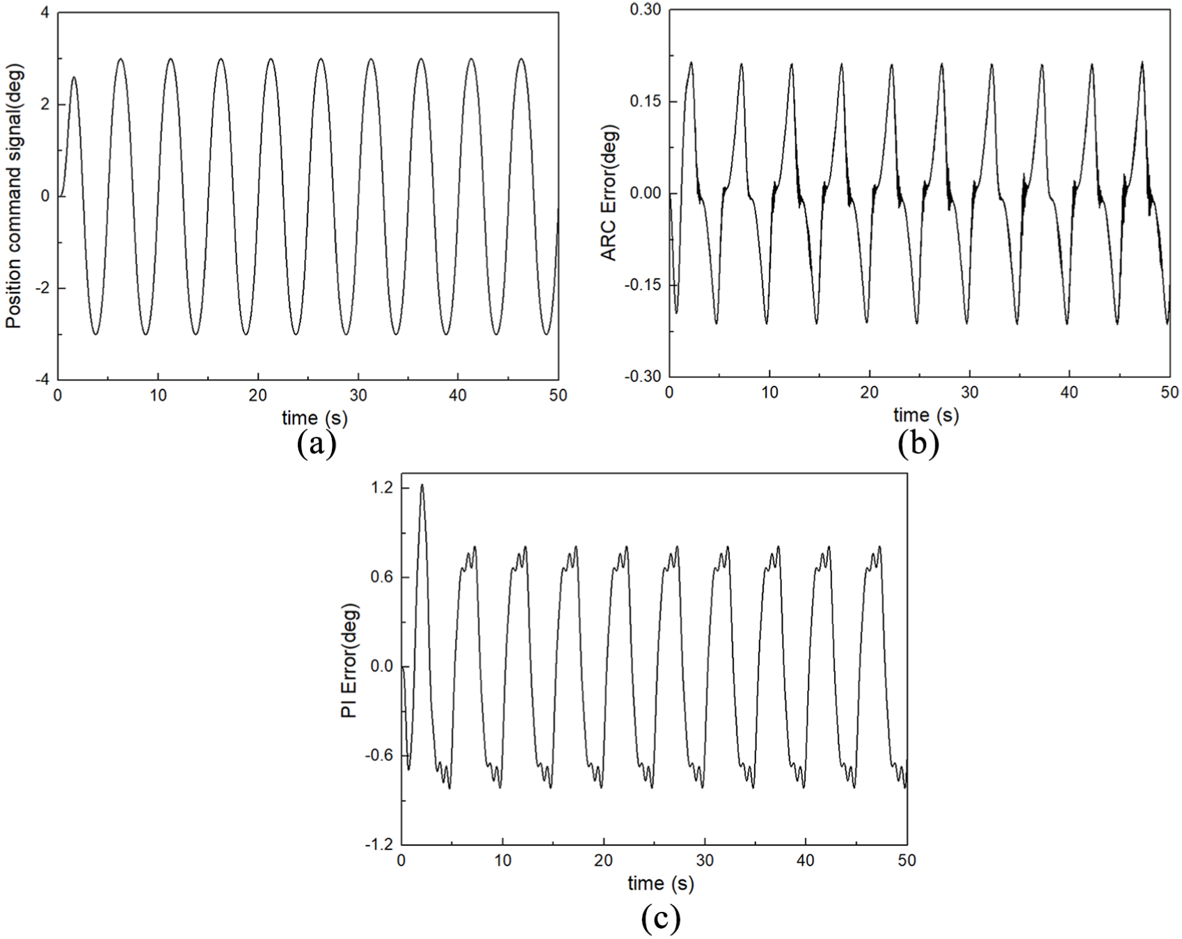
Tracking performance of ARC and PI for sinusoidal motion.
It is interesting to compare the performance indices of the adaptive robust controller and the PI controller in Tables 2 and 3. When the trajectory frequency increases from 0.1 to 0.2 Hz, all the indices of PI controller become larger than those in the previous case, while only a slight increase happens to the proposed model-based adaptive robust controller. Adaptive robust controller outperforms PI controller slightly in test condition 1, but it does much better in this fast test. It can be predicted that with the increase in the tracking frequency, the adaptive robust controller will still be better than the PI controller. The results again verify the effectiveness of the proposed controller.
Conclusion
In this article, an analytical mode of the pendulum boom suspension with parameter obtained from identification techniques is developed, and then the nonlinear model of the hydraulic servo system is derived with consideration of nonlinear behaviors and various modeling uncertainties. An adaptive robust controller for the hydraulic actuator system is designed, taking into account the parametric uncertainties and uncertain nonlinearities. It is implemented on a laboratory setup which consists of the boom suspension, 6-DOF motion simulator, and electro-hydraulic servo system. Comparative experimental results have been obtained to demonstrate the effectiveness of the proposed control scheme in roll movement control of the spray boom, which outperforms the conventional PI controller much more with the increase in trajectory frequency. In future work, the effectiveness and stability of the controller will be tested under different field conditions and the influence of field measurement noise on the adaptive robust controller will be studied.
Footnotes
Appendix 1
Handling Editor: Ali Kazemy
Declaration of conflicting interests
The author(s) declared no potential conflicts of interest with respect to the research, authorship, and/or publication of this article.
Funding
The author(s) disclosed receipt of the following financial support for the research, authorship, and/or publication of this article: This research was supported in part by the National Key Research and Development Program of China (grant no. 2016YFD0200705) and the National Natural Science Foundation of China (grant no. 51605236).