
Abstract
In order to achieve autonomous operation, the kinematics model and experiment system of telescopic excavator are studied. Firstly, the operation space of the robotic excavator is classified and mapping models between different spaces are established based on the D-H method and geometrical relationship method. Then, the virtual prototype of the telescopic robotic excavator is built based on the SimMechanics software, leveling operation and digging operation are simulated; kinematics model and virtual prototype are tested and verified. Finally, experimental system is developed and trajectory tracking experiment is carried out. By comparing with the simulation results, the validity of the proposed control scheme is verified. The research of this article laid foundations for further study and application.
Keywords
Introduction
Hydraulic excavator is an important and indispensable mechanism equipment in all sorts of dirt and stone work, which is applied widely in the industry, civil building, traffic transportation, hydraulic engineering, opencast mining, and modern military project. 1,2 Electromechanical integration and automatization have become the development trend of construction machinery. The autonomous operation excavators are necessary in work sites which are hazardous to human beings. 3 –5 The most immediate application of autonomous excavator is to cleanup operations at sites where toxic and nuclear wastes have been stored. Another application is the excavation on the moon and other planets. In addition, the automatization of hydraulic excavator is also required to improve operation efficiency, safer performance, more comfortable environment as well as better operation quality.
Many scholars have focused their research on the robotic excavator and have already made certain progress. Stentz et al. 6 proposed a completely autonomous operation scheme for the truck loading task, the truck, soil face, and obstacles were recognized and localized by two scanning laser range finders. Ha et al. 7 proposed impedance control for a backhoe excavator, but the control algorithm can hardly be widely used, because of its demand for dynamic model with high precision. Gu et al. 8 investigated various control systems for a robotic excavator, whose results demonstrated that state dependent parameter +proportional integral plus (SDP-PIP) controller can provide improved performance. However, current research mainly focus on the common excavator, 9 –12 there are few reports about the research on the telescopic excavator, which has the greater flexible operation mode and the bigger operation range. So the research on spatial kinematics 13 –15 of telescopic robotic excavator has significant value based on virtual prototype 16 –19 and experiment research.
The paper is organized as follows: In ‘Overview of telescopic excavator’ section, the structure characteristics and operation space classification of telescopic robotic excavator are analyzed. In ‘Kinematics modeling’ section, forward kinematics, inverse kinematics, and mapping models between actuator space and joint space are built. In ‘Simulation analysis’ section, the virtual prototype of the telescopic robotic excavator is developed based on the SimMechanics /MATLAB software; leveling operation and digging operation are analyzed through simulation. In ‘Experiments’ section, experiment system is developed and trajectory tracking experiment is carried out. Finally, conclusions are presented.
Overview of telescopic excavator
The telescopic excavator is a kind of backhoe hydraulic excavator whose arm is adjustable, which consists of lower frame, upper frame, and attachment. The attachment is fixed to the end of upper frame and is modeled into boom, arm, telescopic arm, and bucket as shown in Figure 1. The upper frame can rotate relative to the lower frame. The rotational motion of boom, arm, and bucket are actuated by three linear cylinders controlled by three electrohydraulic direction valves accordingly. The prismatic motion of telescopic arm is actuated by a linear cylinder that is controlled by the electrohydraulic direction valve. So the telescopic excavator is a five degrees of freedom system consisting of swing link, boom link, arm link, telescopic arm link, and bucket link. The telescopic excavator’s operation space can be divided into actuator space, joint space, Cartesian space, and detection space.
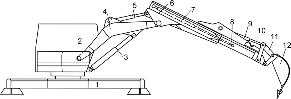
The telescopic excavator. 1. Lower frame, 2. upper frame, 3. boom cylinder, 4. boom, 5. arm cylinder, 6. arm, 7. telescopic arm cylinder, 8. telescopic arm, 9. bucket cylinder, 10. rotating link, 11. connecting rod, 12. bucket.
Kinematics modeling
Kinematics problem can be divided into forward kinematics 20 and inverse kinematics 21 ; the forward kinematics is used to provide guidance for motion control 22 and the inverse kinematics is used to transfer the trajectory 23 of bucket tip to joint space and actuator space. In this section, the kinematics models are built using D-H method and geometric relationship method.
Forward kinematics
Using D-H representation method of robot mechanism, the coordinate systems of the telescopic robotic excavator are established as shown in Figure 2. The link parameters of the telescopic robotic excavator are given in Table 1. The sign a3 stands for equivalent length of arm and telescopic arm.

Coordinate frame for excavator kinematics.
D-H parameters of telescopic excavator.

According to the D-H principle, the coordinate transformation matrix from the coordinate system of the joint i to i − 1 is as follows

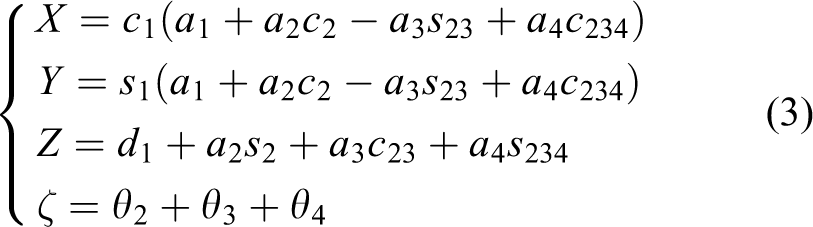
The parameters listed in Table 1 are substituted into equation (1) and the transformation matrixes of near two links can be obtained. Then, the transformation matrix from the bucket tip to base coordinate system is obtained as follows
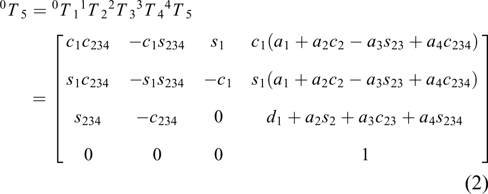
where si = sinθi, ci = cosθi, sij = sin(θi + θj), cij = cos(θi + θj), sijk = sin(θi + θj + θk), cijk = cos(θi + θj + θk), and i, j, k = 1, 2, 3, 4.
Thus, the position and orientation of the bucket tip in Cartesian coordinate system is as follows
Inverse kinematics
When the position and orientation of the bucket tip are given in Cartesian space. The formula for the rotation angle of the upper frame is as follows

In order to simplify the calculation process, the origin of reference coordinate system is translated to the point where the boom intersects the upper frame. The new frame is called

Simplified structure diagram of excavator.
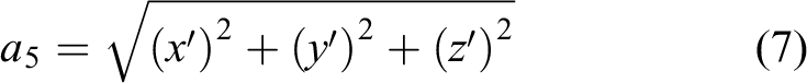
The coordinates of the bucket tip in the new reference coordinate system can be expressed as follows

The length of the telescopic arm is adjustable according to the distance between the rotation center of upper frame and the target point before each operation cycles. Because the length of telescopic arm remains constant during an operation period, the equivalent length of the arm a3 is regarded as a constant. In Figure 3, the hinge point coordinates of bucket can be determined as follows

Thus

According to the trigonometric function

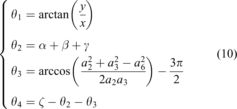
Finally, the inverse kinematics model of telescopic robotic excavator is expressed as follows
Mapping between actuator and joint space
The diagrammatic sketch of telescopic robotic excavator is shown in Figure 4. The mapping relations between actuator space and joint space are calculated by geometric method.

Mapping between actuator space and joint space.
Mapping model of boom
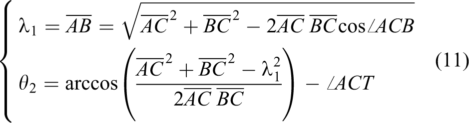
According to the geometrical relationship of boom structure in Figure 4, the points C, B and F are collinear and ∠ACB = θ2 + ∠ACT, where ∠ACT is a constant. Hence, the mapping model between λ1 and θ2 can be expressed as follows
Mapping model of arm
According to the geometrical relationship of arm structure in Figure 4

where ∠CFQ = 3π/2 + θ3 (θ3 is negative). Equation (12) may be written as

Based on the law of cosines, in the ΔDEF

Hence, the mapping model between λ2 and θ3 can be expressed as follows

Mapping model of telescopic arm
When the telescopic arm hydraulic cylinder does not extend,

The mapping model between λ3 and a3 can be expressed as follows

where
Mapping model of bucket
(1) Calculate λ4 with given θ4
According to the geometrical relationship of bucket structure in Figure 4, the following equation is obtained

The displacement of bucket cylinder can be calculated as follows

(2) Calculate θ4 with given λ4
According to the geometrical relationship of bucket structure in Figure 4, the equation (20) is obtained
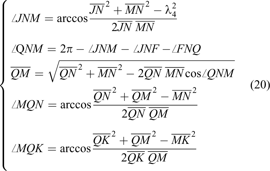
Finally, the joint angle of bucket linkage can be calculated as follows

Simulation analysis
The virtual prototype of the telescopic robotic excavator is built based on the SimMechanics/MATLAB platform. Then, leveling operation and digging operation are used to verify the correctness of the kinematics models.
Virtual prototype modeling
SimMechanics software is a block diagram modeling environment for the kinematics and dynamics modeling and simulation of rigid multi-body systems. Because SimMechanics software is based on the Simulink/MATLAB, SimMechanics simulation model can run within the Simulink environment and interfaces seamlessly with the rest of Simulink and MATLAB. Before and during simulation, SimMechanics software provides visualization tools to display and animate three-dimensional (3-D) machine geometries. There are two kinds of methods to build the simulation model in SimMechanics: using the modules of SimMechanics software directly and using 3-D modeling software.
In this article, first, the 3-D assembly model of telescopic robotic excavator is built using SolidWorks software. Then the virtual prototype of telescopic robotic excavator is built using transform interface between SolidWorks and SimMechanics. The lower frame model is simplified because walking function is not studied. The 3-D visual model of the telescopic excavator is shown in Figure 5 and the module chart of the robotic excavator is shown in Figure 6. The modules represent rigid body structures of telescopic robotic excavator and constrains between them. When the motion trajectories of the hydraulic cylinders have been planned, the 3-D visual simulation can be carried out.

Three-dimensional visual simulation model.

Module chart of the telescopic excavator.
Kinematics simulation
The operation tasks of the telescopic robotic excavator are given in Cartesian space, while the bucket motion is driven by the hydraulic cylinders in actuator space. In order to avoid complex kinematics calculations, the key point poses of the bucket tip are planned in Cartesian space according to the operation stages, and then the joint angles and cylinder displacements are calculated based on the inverse kinematics model. The motion commanding signals are generated in the actuator space using the interpolation algorithm eventually. In order to track the predetermined trajectory clearly, the displacements of the bucket tip and hydraulic cylinder displacements are measured by the sensors in virtual prototype.
Leveling operation simulation
Let the starting point and terminal point of the leveling operation be P0 and Pend, where P0 = [7500 0 − 1000] T and Pend= [5500 0 − 1000]T, expressed in millimeters. Firstly, the trajectory of bucket tip is obtained using the equidistant linear interpolation algorithm. Then, the trajectories of joint angles and the hydraulic cylinder displacements are calculated based on the inverse kinematics model. The joint angle are shown in Figure 7 and the hydraulic cylinder displacements in Figure 8. It can be seen that the curves of both joint angle and hydraulic cylinder displacements are continuous and smooth. Figure 9 shows the motion trajectory of the bucket tip in the XZ plane.

The angular displacement curves.
The cylinder displacement curves.

The bucket tip trajectory in the XZ plane.
As can be seen from the Figure 9, the maximum error is 17 mm in x-axis direction and the maximum error is 12 mm in z-axis direction, and the error is mainly due to calculation precision.
Digging operation cycle simulation
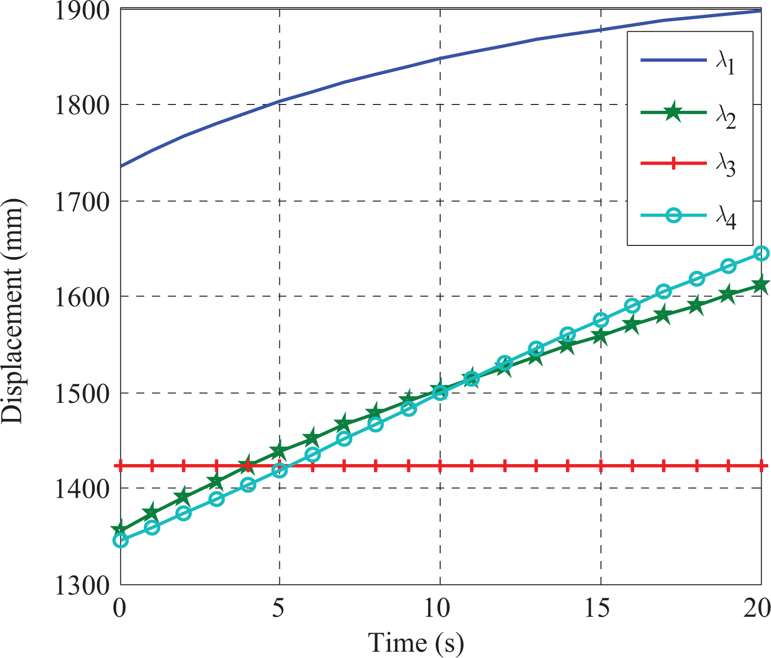
Every digging operation cycle can be divided into seven phases, including adjusting telescopic arm, positioning, digging, lifting, rotating, discharging, and returning. Assuming the digging starting point is (6500 0 1000), the unit is mm, then turned left 45° and discharge. Let the time of each phase is 5 s. Figures 10 and 11 show the joint angle and hydraulic cylinder displacement curves, respectively.

Joint angles of the attachment.

Displacements of the hydraulic cylinders.
In the first phase, the telescopic excavator is focused on adjusting the telescopic arm cylinder displacement. It can be seen that the joint angle displacements stay the same, the telescopic arm cylinder displacement ranges from 1756.9 to 2677.2 mm and then remains constant within 5–35 s. In the second phase, the telescopic excavator is focused on adjusting the hydraulic cylinder displacement to locate the bucket tip to the digging starting point within 5–10 s, which is a composite motion of the boom, arm, and bucket cylinders. In the third phase, the telescopic excavator is focused on the digging operation within 10–15 s. At this time, the displacement of the bucket cylinder shows the biggest change, which is consistent with the actual condition. In the fourth phase, the telescopic excavator is focused on lifting the bucket to a desired height within 15–20 s, which is a composite motion of the boom and arm. In the fifth phase, the telescopic excavator is focused on turning the bucket to a desired position within 20–25 s, which is just a rotational movement of the upper frame; the rotation angle ranges from 0 to 45° and other joints stay the same. In the sixth phase, the telescopic excavator is focused on discharge within 25–30 s, which is just the bucket joint movement. The bucket cylinder displacement reduces to a minimum. In the seventh phase, the telescopic excavator is focused on returning to the next digging starting point within 30–35 s. Now the telescopic excavator fulfills a digging operation cycle. The corresponding motion trajectory of the bucket tip is shown in Figure 12.

Displacement of the bucket tip.
Figure 13(a) to (h) shows digging operation cycle of the telescopic robotic excavator at the time steps of 0, 5, 10, 15, 20, 25, 30, and 35 s, respectively.

The operation process of the telescopic excavator. (a) Initial state. (b) Adjusting. (c) Positioning. (d) Digging. (e) Lifting. (f) Rotating. (g) Discharging. (h) Returning.
Simulation results
It can be seen from leveling operation and digging operation simulation that virtual prototype of the telescopic robotic excavator can fulfill required tasks, whose control commands are obtained based on the kinematics model. The simulation results show the validity and accuracy of kinematics model and virtual prototype of the telescopic robotic excavator. Meanwhile, the operation status can be measured numerically and the components interference can be checked visually. Therefore, the virtual prototype is a useful tool in monitoring motion and identifying possible interference between various components. The kinematics simulation presented in this section lays the foundation for complete spatial trajectory planning and control system design.
Experiments
In this section, experiment system of the telescopic robotic excavator is developed and trajectory tracking experiment is carried out.
Experiment system
The experiment system of the telescopic robotic excavator is reconstructed from the existing backhoe excavator, whose hydraulic system is rebuilt by replacing the manual valves with electro-hydraulic proportional servo valves (EHPS). The experiment system is composed of backhoe excavator, control system, a 3-D laser radar, and cable-type absolute encoders. The structure of the telescopic robotic excavator is shown in Figure 14. The laser radar and telescopic arm encoder are mounted at the arm, the hydraulic cylinder displacement encoders are mounted on boom, arm, bucket cylinder, respectively, and a revolving encoder and a two-dimensional tilt sensor are mounted on upper platform.

Experiment system of the telescopic excavator.
The telescopic robotic excavator is an integration system that includes environment description, autonomous decision and planning, behavior control and robot technology, and other functions. The composite control system of the telescopic robotic excavator is shown in Figure 15, which is mainly composed of the perception layer, decision layer, planning layer, trajectory tracking, and coordination layer and electrohydraulic proportional control system.

Schematic diagram of control system.
Decision, perception, and planning layer
The decision layer, the perception layer, and the planning layer system are composed of the host computer, digging surface environmental sensor (3-D laser radar), internal sensors (pressure sensors of electro-hydraulic servo system), and cable-type absolute encoders used to feedback the displacement signals of hydraulic cylinder pistons to realize closed loop control. The planning layer is used to calculate the trajectory of each joint according to decision layer command and the feedback information of perception layer, including the space position of the excavator in basic coordinate system, the pressure and piston rod displacements of the hydraulic cylinders, and so on.
Trajectory tracking and coordination layer
Trajectory tracking and coordination layer system is composed of lower computer controller. According to the trajectory planned by the planning layer and the feedback signals of perception layer, trajectory tracking and coordination layer produce the motion control scheme for the telescopic robotic excavator under the coordination of the system synchronization clock.
Joint control system
The electrohydraulic proportional position control system of the robotic excavator is composed of digital control drive module HC-G19, pressure sensors, cable-type absolute encoders, and electrohydraulic proportional system including pilot proportional pressure reducing valve, load independent flow distribution (LUDV) valve, and the hydraulic cylinders. In view of the nonlinear and load variation characteristics of the robotic excavator position control system, a nonlinear proportional integral derivative (PID) control algorithm is proposed. The output of nonlinear PID controller is as follows

where ap, bp, cp, ai, and ad are constants.
Experiment analysis
Several coordinate points are selected as track targets of the bucket tip within the operation range. The trajectories of joint space and actuator space can be calculated based on the inverse kinematics model. Firstly, the virtual prototype is tested and the motion trajectory of the bucket tip and hydraulic cylinder displacements can be obtained by the virtual sensor directly. Then, the experiment is carried out using the same simulation data. In the course of the experiment, the hydraulic cylinder displacements can be measured using the cable-type absolute encoders, and then the actual trajectory of the bucket tip can be calculated based on the forward kinematics model. Simulation and experiment results are shown in Table 2, where the first four columns of the table are cylinder displacements and the latter part are x-axis and z-axis coordinate values. The motion trajectory of the bucket tip are shown in Figure 16.
The values of simulation and experiment (unit: mm).a

aSummary: Maximum error of x-axis: 25.4 mm; average error of x-axis:16.16 mm, and Maximum error of z-axis: 16.6 mm; average error of z-axis: 8.24 mm.
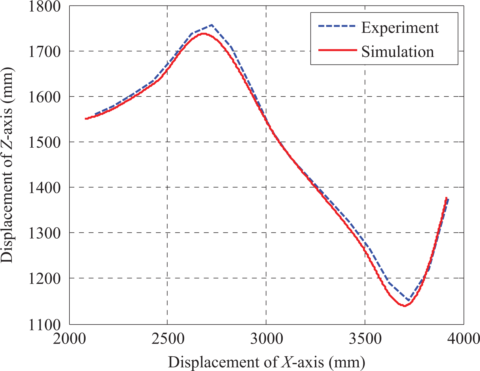
Experiment and simulation results.
Experimental results
It can be seen from the Table 2 and Figure 16 that the maximum errors in x-axis and z-axis directions are 25.4 and 16.6 mm, respectively; the average errors in x-axis and z-axis directions are 16.16 and 8.24 mm, respectively. The errors are mainly from errors of manufacturing, assembly, the mathematical calculation, and so on. But the errors between simulation and experiment are in an acceptable range. The experimental results show good consistency with simulation results. Hence, it may be concluded that the virtual prototype is feasible to study the real operation process and experimental control system is practical and effective. The kinematics models and virtual prototype of the telescopic robotic excavator are tested and verified. The experimental results also show the effectiveness of control method and system, making it a good preparation for further improvement and research.
Conclusions
The spatial kinematics characteristics of the telescopic robotic excavator is analyzed and verified based on the virtual prototype and physical prototype. The mapping relations of Cartesian space joint space and actuator space of the robotic excavator are established based on the kinematics model, which lays the theoretic foundation for trajectory planning and controls. 3-D visual simulation and numerical analysis are realized based on virtual prototype, and the characteristics of leveling operation and digging operation are analyzed. The composite control system and nonlinear PID control algorithm are proposed. The trajectory tracking experiment is carried out. The experiment results are in agreement with the simulation results, which indicate that the research method is valid. The paper lays foundations for the further study and application.
Footnotes
Declaration of conflicting interests
The author(s) declared no potential conflicts of interest with respect to the research, authorship, and/or publication of this article.
Funding
The author(s) received no financial support for the research, authorship, and/or publication of this article.