
Abstract
A statically designed derrick of deep oil well drilling rig may have poor dynamic characteristics, which can cause earlier structure failure of the drilling rig and harsh working condition. One such designed derrick is found to vibrate severely in operation while the rotation speed of rotary table is about 120 r/min with the working frequency of 2.0 Hz. To solve this problem, an experimental modal test of the derrick is conducted and the modal frequencies and vibration shapes are obtained. Through comparison of modal frequencies with that of exciting devices, it is found that the severe vibration of the drilling rig is caused by the resonance of second modal frequency (1.96 Hz) and the working frequency of rotary table. Based on principles of sensitivity analysis and structural dynamics modification method, the frequency sensitivities of all nodes on the derrick are calculated and compared, and then seven nodes with high-frequency sensitivity are selected on which corresponding mass are added to vary the modal frequency. Result shows that the second modal frequency of the derrick is reduced to 1.42 Hz and is out of the normal working frequency range of rotary table, which demonstrates that the dynamic characteristics of the derrick is improved and severe vibration can be avoided.
Keywords
Introduction
Besides huge static loads, the drilling rig used to drill deep oil well bears periodical dynamic loads caused by the operation of rotating devices such as rotary table and gear reducer. In traditional design of derrick, it is merely required to meet the requirement of static strength and there is no consideration for dynamic performance. Thus, the designed derrick may have sufficient static strength, but poor dynamic performance which might cause unexpected vibration during the drilling process, leading to negative influence on the safety and efficiency of drilling operation. Under this circumstance, the dynamic characteristics of derrick should be made clear and improved if necessary.
Over the past decades, with the development of the technology for computer modeling and dynamic testing, structural dynamics modification (SDM) has received broad attention from researchers and engineers. Some concrete SDM methods, including matrix perturbation,1,2 weighted Euclidean norm,3,4 transfer function,5,6 and sensitivity analysis,7,8 have been developed and applied in the fields of aerospace, aviation, construction, bridge, electricity, energy, and so on. For large equipments in service, frequency sensitivity method offers an easily implementable and effective way for SDM. The basic idea of SDM method is to determine the parameters to be changed through sensitivity analysis and then modify these parameters to improve the structure’s dynamic characteristics.9–11 A lot of work about this have been done which can provide us beneficial references.
Wang 12 developed a dynamic modification program, in which modal synthesis and unified iterative method were adopted to account for the sensitivity of modal parameter and quadric layout method, and genetic algorithm was used to solve dynamic modification of structure. Ding and Miao 13 conducted SDM for a partial structure of a car body of the high-speed train, the natural frequency of which was increased through the modification. Guo 14 calculated the frequency sensitivity of the mast of a truck-mounted drilling rig and then improved the anti-vibration ability of the mast by modifying the cross-sectional parameters of structure parts. Yu and Wang 15 determined the key modal frequencies of a tower crane through modal analysis and harmonic response analysis. He calculated the sensitivity for important structural parameters and then carried out the optimization design in which the modal frequency of second modal was set as optimization objective, aiming to improve the anti-vibration performance of the tower crane. Based on modal test and sensitivity of a vehicle frame, Zhang and Fan 16 conducted mass and stiffness modification for the frame, through which the ride performance of the frame was improved.
Although SDM has already been used in different fields, there is little information available in literature about research of SDM for the derrick of deep well drilling rig. In order to reduce the severe vibration of a deep well drilling rig during its operation when the rotation speed of rotary table is about 120 r/min, we conducted the experimental modal test for the derrick and calculated each modal frequency sensitivity to mass eigenvalue. Based on the test, we successfully solved the problem of severe vibration of drilling rig by mismatching the second modal frequency with the working frequency of rotary table through modifying the mass of corresponding node.
Theoretical aspects
Sensitivity analysis
Sensitivity analysis is used to determine the rate of eigenvalues and eigenvectors of structure varying with the mass, stiffness, and damping, which provides the theoretical basis for SDM. The specific position of the structure will be indicated through sensitivity analysis, where the modification has the greatest influence on dynamic characteristics of the structure and is the most effective. By identifying this, we can avoid the blindness of the SDM process, improve the SDM efficiency, and reduce the cost.
For a vibration system with viscous damping, the first-order sensitivity equation of structure eigenvalues on structure parameters can be expressed as 17

where λr is the modal shape eigenvalue of rth order; {ψr } is the modal vector of rth order; pm is the structure parameter; and [M], [C], and [K] are mass matrix, damping matrix, and stiffness matrix of structure, respectively, all of which are symmetric matrixes with the same order.
Equation (1) indicates that λr
is more sensitive on the change pm
with the increase in absolute value of


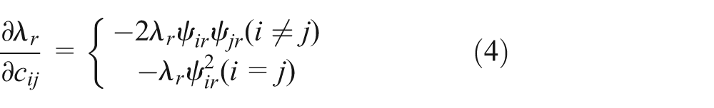
Equations (2), (3), and (4) represent, respectively, the sensitivity of structure eigenvalues on structure parameter of mass, stiffness, and damping.
SDM based on sensitivity analysis
Sensitivity method for SDM, which is on the basis of sensitivity analysis of structure eigenvalues, determines the variation of structure eigenvalues using Taylor expansion of multivariate function. Generally, the structure eigenvalue λr is a multivariate function of structure parameters mij , kij , and cij , that is

where mij , kij , and cij , respectively, represent the element of column j and row i in mass matrix, stiffness matrix, and damping matrix.
By expanding equation (5) into Taylor series and omitting high-order terms, we get
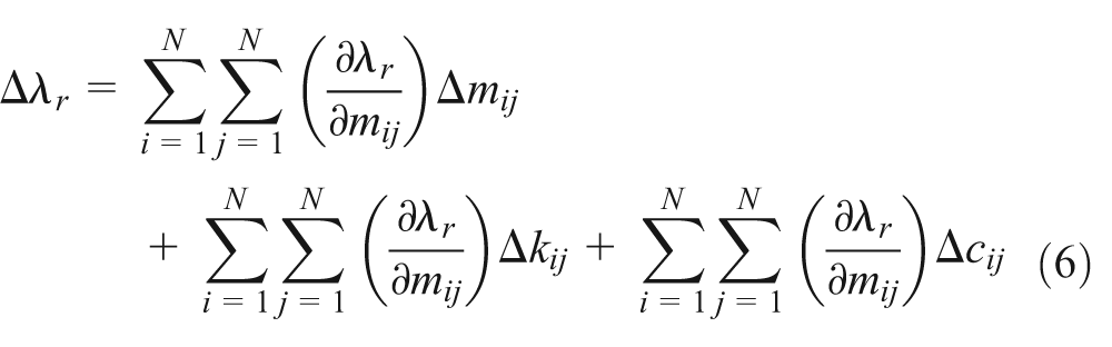
According to equation (6), the variation of structure eigenvalue Δλr can be calculated if modification of structure parameters Δmij , Δkij , and Δcij are determined, and the modified structure eigenvalue λr becomes

Theoretically, structure’s mass, stiffness, and damping matrixes can be modified together; however, according to the site conditions and economic requirements, only one or two structure parameters are often selected to modify in practical application.
Experimental modal test of derrick
Test method and devices
Generally, there are two ways for conducting the modal analysis of a practical structure, namely, experimental modal analysis and computational modal analysis. Compared with computational modal analysis via numerical method, experimental modal analysis can achieve higher accuracy. In this study, the hammering test method was conducted on the derrick of a deep well drilling rig which was observed to have severe vibration in drilling process.
UT3316 dynamic signal analysis system was adopted in the modal test, which includes UT3316 ICP signal acquisition unit, BZ2109 multi-channel charge amplifier, LC-02A impact hammer with maximum impact force of 5000 N, CL-YD-312A piezoelectric force sensor (sensitivity 3.73 PC/N), KD series piezoelectric acceleration sensors (sensitivity from 5.043 to 9.980 mV/ms2), data lines, laptop, and uTekMa modal analysis software.
Modeling of derrick
The drilling rig is equipped with K-type derrick designed by modularization technology, as shown in Figure 1(a). The total height of the derrick is 53.5 m, effective height is 45 m and it weighs approximately 10 tons. The derrick is assembled from dozens of parts including connecting frame, oblique struts, beams, A-frame, and emergency escape device. Each loading component is welded from profile steel, while all the sections of the derrick are connected with pins.
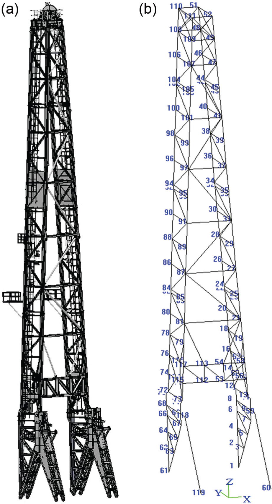
Three-dimensional model and dot–dash model of the derrick: (a) detailed three-dimensional model of the derrick and (b) dot–dash model of the derrick and corresponding coordinates.
Based on structure and size of the derrick, we established the dot–dash model by treating the welding points between links as nodes. In order to highlight the vibration of main structure, the model was properly simplified by omitting some partial structures such as ladders and second floor platform. Figure 1(b) shows the completed dot–dash model of the derrick and corresponding coordinates.
Considering the vibration observed in drilling field was in X-Z plane, the experimental modal was focused on the modal along X-direction. Totally, 15 acceleration sensors were positioned along a main leg of the derrick with the corresponding nodes in the model were 74, 76, 78, 80, 84, 86, 88, 90, 94, 96, 98, 100, 104, 106, and 108. Node 16 was selected as the exciting point which is located near the bottom of the derrick. Shown in Figure 2 is the local view of node 104 and the acceleration sensor.
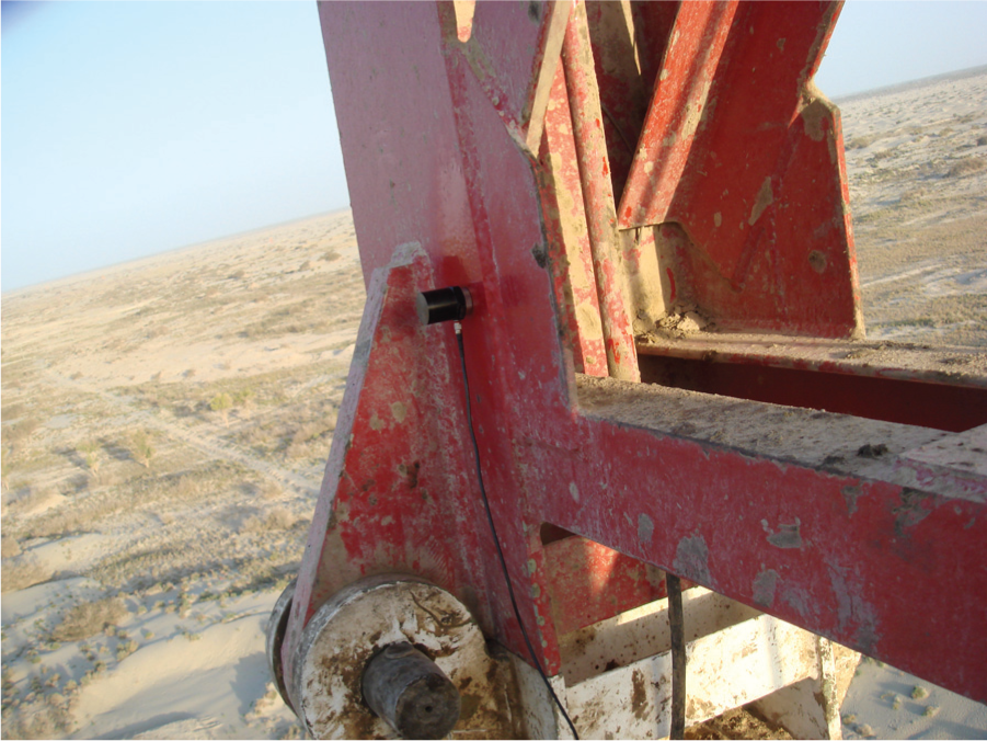
Location of node 104 and corresponding acceleration sensor.
Modal test result and analysis
Figure 3 shows the lumped average curve of frequency response function, on which six peak points were selected and fitted to obtain the modal parameters of the derrick. Figure 4 illustrates the modal assurance criterion; it can be seen that the maximum value is between first order and fourth order with the value of 0.412, which means the arrangement effect of acceleration sensor is well accepted.

Lumped average curve of frequency response function.

Modal assurance criterion.
The first six-order modal shapes of the derrick are shown in Figure 5(a)–(f). The related modal frequencies are listed in Table 1. By observing and analyzing Figure 5, we found that all the modal shapes appear bending vibration in X-Y plane, the first two orders of which are first bending vibration and the next four orders are second and higher order bending vibrations. Table 1 demonstrates that the lowest modal frequency of the derrick is 1.01 Hz, while the highest one is 8.05 Hz. The modal frequencies are in accordance with the relative data presented by Liu et al. 18 and match the vibration characteristic of large steel structure, which means the modal test result is credible.

Modal shapes of first six orders: (a) first order, (b) second order, (c) third order, (d) fourth order, (e) fifth order, and (f) sixth order.
Modal frequencies of first six orders.

During drilling operation, the common rotation speed of the rotary table is between 90 and 120 r/min, that is, the working frequency ranges from 1.5 to 2 Hz. The live monitoring and recording data show that when the rotation is about 120 r/min, the derrick vibrates severely, especially on the top. Figure 2(b) also shows, on the top of the derrick, that there is a large modal displacement. The efficiency of drilling process and the structural strength of the drilling are subject to reduction by the vibration. We found that the second modal frequency (1.96 Hz) of the derrick was in the range of rotary table working frequency and was very close to 2 Hz. So, we concluded that the match of working frequency of rotary table and second modal frequency of derrick excited the second modal of the derrick and led to severe vibration.
Structural dynamics modification
According to the above analysis, it is already known that the severe vibration of the derrick was caused by the frequency match between second mode and working frequency of rotary table. To avoid the frequency match, it is necessary to modify the structure of the derrick and to make its second modal frequency far away from the working frequency of rotary table.
Sensitivity analysis
Because the drilling rig has been in operation state in oil field, the most effective and economical way for SDM is modifying the node mass matrix, which can be implemented by welding mass block on corresponding nodes. Theoretically, the modal frequency of the derrick can be changed by adding mass on any nodes; however, it is always expected to achieve a better modification effect by adding the same mass. Furthermore, it must be avoided that the modal frequency of some other modes enters the range of rotary table working frequency while the second modal frequency is out of the range. Therefore, the frequency sensitivity to all nodes should be calculated first, and then only those nodes with higher sensitivity to second mode and lower sensitivity to other modes are selected to add mass. In this study, based on the sensitivity analysis, seven nodes are selected which are listed in Table 2, with sensitivity value of each mode.
Sensitivity data for the seven selected nodes.

It can be seen from Figure 1(b) that nodes 48,49,108, and 109 are located around the second section on the upper part of the derrick, node 46 is right below node 48, and nodes 14 and 15 are on the bottom right of the derrick. These nodes have relatively higher frequency sensitivity to second mode and lower sensitivity to other modes, among which node 48 has the highest frequency sensitivity of 4.32 × 10⁻³ Hz/kg to second mode. It means if we add mass of 1 kg on node 48, the second modal frequency of the derrick will be decreased by 0.00432 Hz.
Modification of node mass
On the basis of sensitivity analysis, we conducted SDM for the derrick by adding mass block on the nodes above. The concrete modification solution, decided after multiple numerical simulations, is to add 30 kg of mass block on nodes 48 and 109, 20 kg of mass block on nodes 48 and 109, and 25 kg of mass block on nodes 46, 14, and 15. The modal frequency data of modified derrick are listed in Table 3.
Structural dynamics modification (SDM) scheme for derrick and modal frequencies after modification.

From Table 3, it can be found that via the SDM of the derrick, the second modal frequency was changed with large variation compared to all modal frequencies. From 1.96 to 1.42 Hz, it was decreased by 25% and was not in the working frequency (1.5–2 Hz) range of rotary table. Meanwhile, other modal frequencies were also changed but with small variations and still out of the working frequency range of rotary table. So, the dynamic characteristics of modified derrick is much better than that of the original, which means the severe vibration excited by rotary table could be reduced effectively.
Conclusion
One derrick of a deep well drilling rig was found to vibrate severely under specific rotation speed of rotary table. To fix the problem, an experimental modal test was conducted to obtain vibration shape and modal frequency. Through data analysis, it was found that the vibration of derrick was caused by the match between second modal frequency and working frequency of rotary table.
Based on principle of sensitivity analysis and SDM, the frequency sensitivity of all nodes on the derrick was calculated, and then proper nodes were selected on which mass blocks were added to carry out the SDM. Using SDM, the second modal frequency of the derrick was changed to be out of the working frequency range of the rotary table, and consequently, the dynamic characteristics of the derrick was improved and the vibration problem was solved well.
Footnotes
Academic Editor: Ling Zheng
Declaration of conflicting interests
The author(s) declared no potential conflicts of interest with respect to the research, authorship, and/or publication of this article.
Funding
The research described in this article was supported by Petro China Innovation Fund Program (2014D-5006-0310) and Educational Commission of Hubei Province, China (D20141304).