
Abstract
For engineering structures, there is a strong need to assign natural frequencies to achieve desired dynamic performance. This study proposes a receptance-based frequency assignment method for assembled structures. Very often, the substructures involved are not allowed or are difficult to change. This method uses the links between the substructures as targets of structural modifications and determines the structural properties of the links that assign the desired frequencies cast as an optimisation problem. These links could be either simple discrete structural components such as masses and springs or complex continuous structures. Only a few receptances of the substructures are required in this method, which can be measured accurately and easily in practice. Two numerical examples are presented to show the validity of this method and its strength in dealing with complex assembled structures.
Keywords
1. Introduction
In engineering, structures often experience undesirable vibration and even fail because of fatigue. Frequency assignment is a very effective way to tackle these problems by shifting the affected natural frequencies to desired values (locations). This assignment is usually achieved by making modifications to the mass, stiffness and occasionally damping of the structures.
There are typically two categories of frequency assignment methods: forward and inverse (Li and He, 1999). The forward methods are to determine the eigenvalues and eigenvectors of a system with known modifications. This procedure is repeated until the requirement, such as desired frequencies or modes, is met (Olsson and Lidström, 2007). They are widely used in vibration optimisation and in finite element updating. Baldwin and Hutton (1985) reviewed several structural modification methods that had been proposed before the 1980s, including Rayleigh’s quotient, sensitivity approaches and perturbation approaches. Hang et al. (2010) recently investigated means of efficiently predicting the effects of distributed structural modifications on dynamic response of a complex structure. The inverse methods, in contrast, are to determine the structure parameters such that the modified systems could have desired frequencies and/or modes, which are more intuitive in practical problems (Çakar, 2011; Joseph, 1992; Mottershead, 2001; Nylen and Uhlig, 1997). Some inverse methods rely on system modal data (Braun and Ram, 2001; Bucher and Braun, 1993; Liangsheng, 2003). Braun and Ram (2001) considered the inverse problem of determining the structural modifications which could assign a desired spectrum and developed physically realisable solutions. They showed that it was possible to solve the inverse structural modification problem without truncation error if both left and right eigenvectors of the system are available. However, those methods are difficult to apply to complex structures because accurate modal data are hard to obtain and their solutions are sensitive to errors. To overcome these problems, receptances, which could be directly measured, have been adopted in many inverse dynamic problems. Tsuei and Yee (1989) presented sensitivity graphs of the modification parameters with respect to the desired frequency using the receptance of the unmodified system. In a subsequent article, Yee and Tsuei (1991) improved the method to get the necessary mass and stiffness modifications that assign natural frequencies to a viscously damped system. Kyprianou et al. (2004) assigned natural frequencies to a multi-degrees of freedom (DoFs) undamped system by an added mass and one or more springs. There are new additional DoFs involved in the modifications. The authors (Kyprianou et al., 2005) later assigned natural frequencies or anti-resonances to a portal frame by determining the dimensions of the cross-section of a column as a beam. Zhu et al. (2009) assigned receptances using classical vibration absorbers. The parameters of absorbers were determined using selected receptances from the original system. Çakar (2011) developed a new method which is based on the Sherman–Morrison formula. This method can maintain certain pre-specified natural frequencies unchanged, when the mass and stiffness properties of the structure are modified. Tsai et al. (2018) presented an experimental validation to an inverse frequency assignment method. A gear rotor-bearing system was tested, and several natural frequencies and nodes were assigned by adding masses.
There was usually one structure involved, which was to be modified by changing the existing structural properties of or adding a simple structure to an original structure, in those aforementioned investigations. However, for assembled structures, there would be more than one substructure involved. The above methods could not be directly applied to assign frequencies for assembled structures, especially when the substructures are not allowed or difficult to be modified and only the links between substructures could be changed. For example when an engine is to be installed on a ship, resonance should be avoided. However, the engine and the ship usually come from different suppliers and thus cannot be modified directly. Then, it would be important to carry out structural modifications on the links that connect the engine and ship structure and optimise the links. Therefore, this research aims to establish a receptance-based frequency assignment method, which assigns frequencies to an assembled structure and finds the optimal links between the substructures.
There are already a number of articles on predicting dynamic behaviours of assembled structures. Substructure coupling methods have been widely used to couple substructures and predict their dynamic responses (Craig and Chang, 1977; Liu and Ewins, 2000; Mehrpouya et al., 2015; Schmitz and Donalson, 2000). Those methods, although their initial purpose is not frequency assignment, could also be used to solve forward frequency assignment problems (Imregun, 1987; Mottershead et al., 2005). There are mainly two types of substructure coupling methods: Modal synthesis methods (Craig and Bampton, 1968) and frequency domain methods (Ren and Beards, 1995). Modal synthesis methods usually would produce modal truncation errors, whereas frequency domain methods, using the measured frequency response functions directly, could avoid this problem (De Klerk et al., 2006). De Klerk et al. (2008) presented a general framework which allowed for classification of substructuring methods and highlighted the interrelations between those methods. A reformulation and generalisation of the classical frequency-based substructuring method was introduced by De Klerk et al. (2006). D’Ambrigio and Sestieri. (2004) analysed the feasibility of assembling different substructures’ models, such as frequency response function (FRF) models, modal models and finite element (FE) models, for predicting the dynamic behaviour of assembled structures. Liu and Ewins (2000) reviewed some FRF coupling methods and then proposed a general joint description method for FRF coupling analysis. The FRFs of a plate connected with a beam via a steel bolt were predicted. An inverse substructure method was developed for the analysis of the dynamical characteristics of a three-substructure coupled system based on the inverse substructure method of a two-substructure coupled system by Wang and Wang (2011). Matthias et al. (2016) predicted the frequency response functions at the tool tip of a holder–tool assembly based on receptance coupling substructure analysis.
Although the substructure coupling method, in theory, could be used to assign frequencies by repeating the coupling process with different links until the requirements are met, an inverse method (that would avoid a trial-and-error process) would be more appealing in practice. However, there are few publications about the inverse assignment problems of assembled structures. Birchfield et al. (2013) predicted the dynamic response of a coupled-rotor-system using the receptance functions of individual subsystems. The subsystems were coupled using springs and dampers and the critical speed of the coupled rotor system was changed to a desired value. No additional degree of freedom was introduced when modifying the link.
In substructure coupling methods, those links would be treated as substructures so that the coupling method could be applied. However, this is not efficient when there are multiple links. In this study, the links are treated as modifications of uncoupled substructures and they could be discrete components (masses, springs and dampers) or continuous structures (beams, plates or even more complicated structures). Those links are optimised based on the receptances of the substructures and finite element models of the links. Two numerical examples, respectively with a discrete structure or a continuous structure, are demonstrated to validate this proposed method. The numerical results indicate that this method could be implemented for frequency assignment to complex structures in practice.
2. Theory
This section shows a frequency assignment method for an assembled structure by modifying the properties of its links. The following derivation is based on two substructures and two links. However, it is apparently applicable to an assembled structure with any number of substructures and links.
As shown in Figure 1, substructure A and substructure B are connected through two links C and D. The DoFs of substructure A, ‘ Substructures A and B connected by links C and D.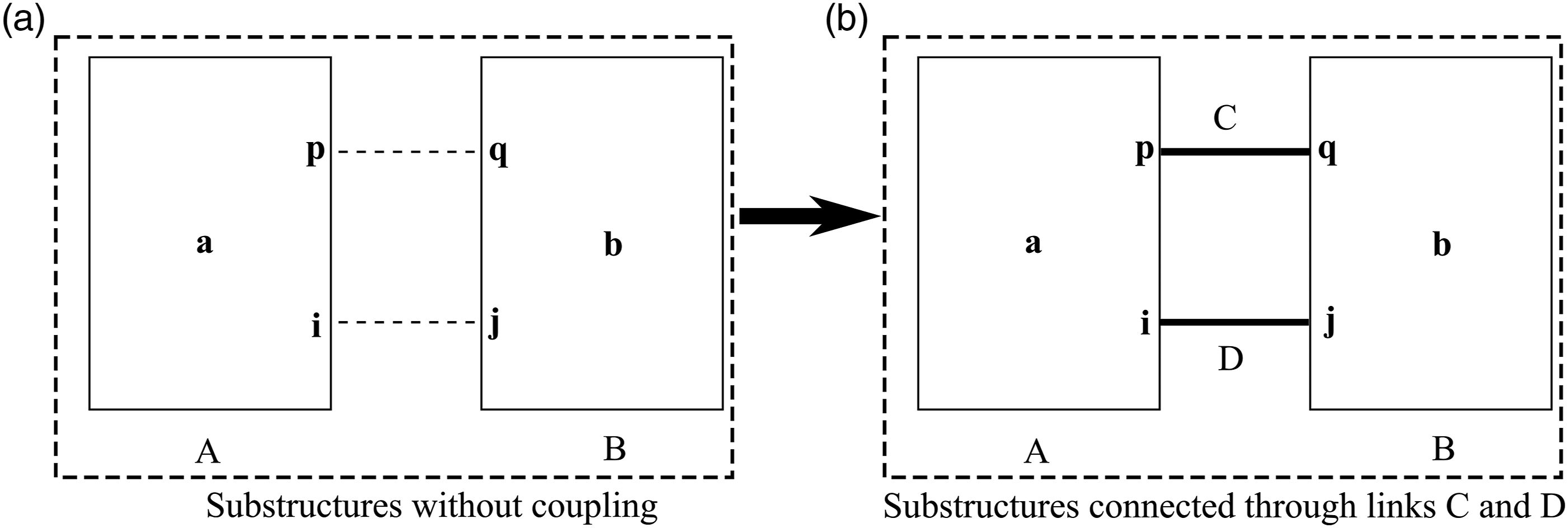
When substructures A and B are connected through links C and D, there will be internal forces, denoted by force vectors Internal forces in the interface degrees of freedom.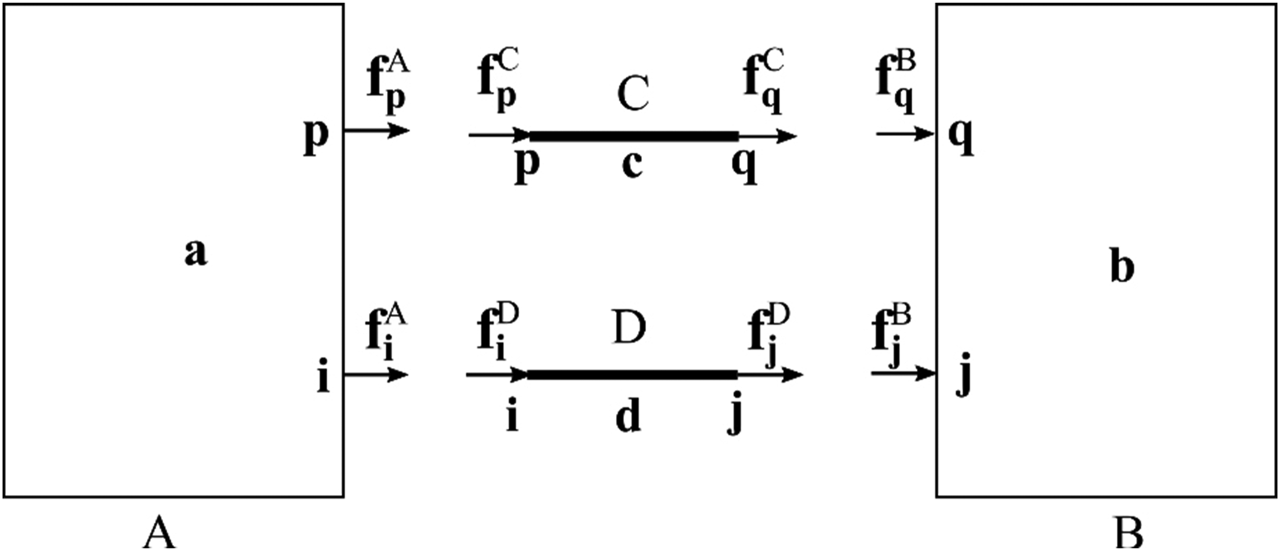
The equations of motion for substructures A and B in frequency domain can be expressed as
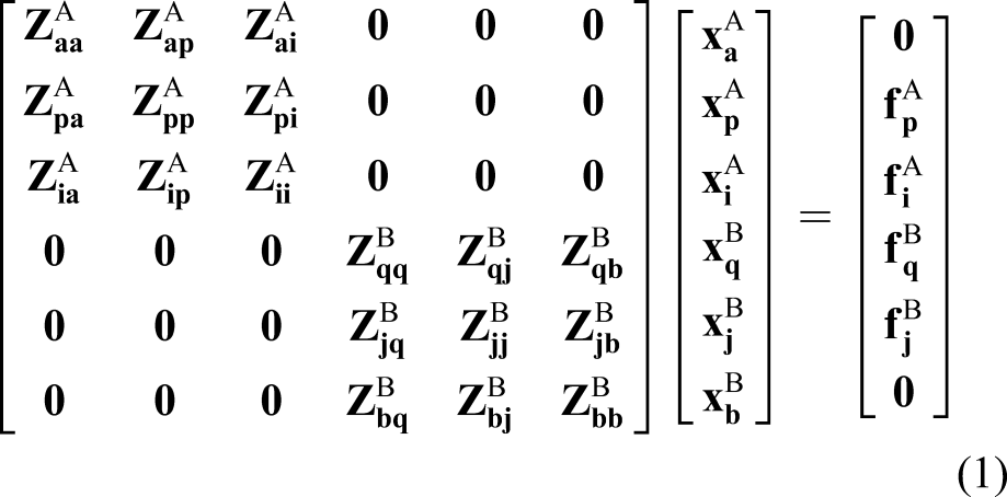
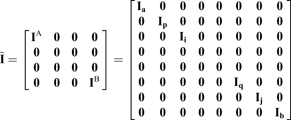
The nine matrix blocks at the top left corner and the nine matrix blocks at the bottom right corner in the matrix of equation (1) can be grouped, respectively as
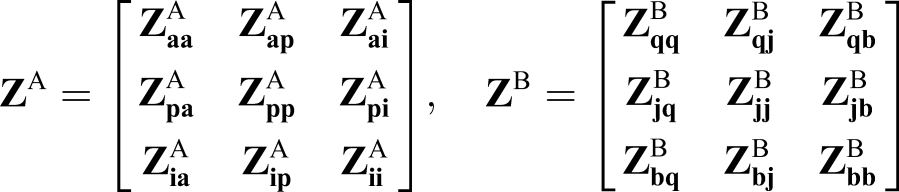
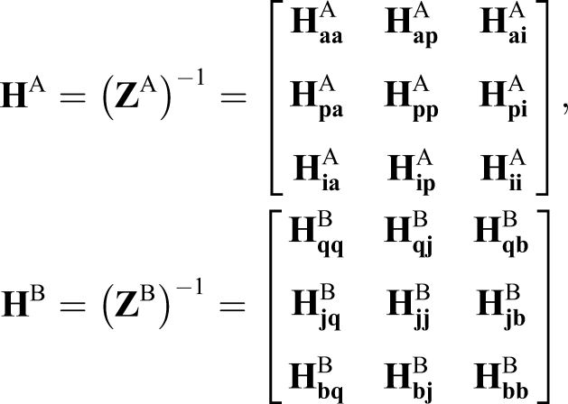
Here,
Similarly, the equations of motion for links C and D can be written as
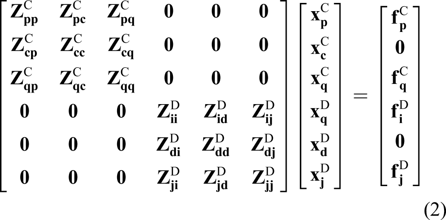
Besides, the conditions of displacement compatibility should be satisfied


Therefore, based on the above equations, equations (1) and (2) could be assembled into one equation below, which is the equation of motion of the assembled structure when without an external excitation

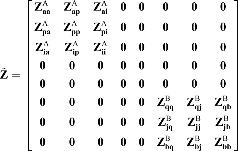
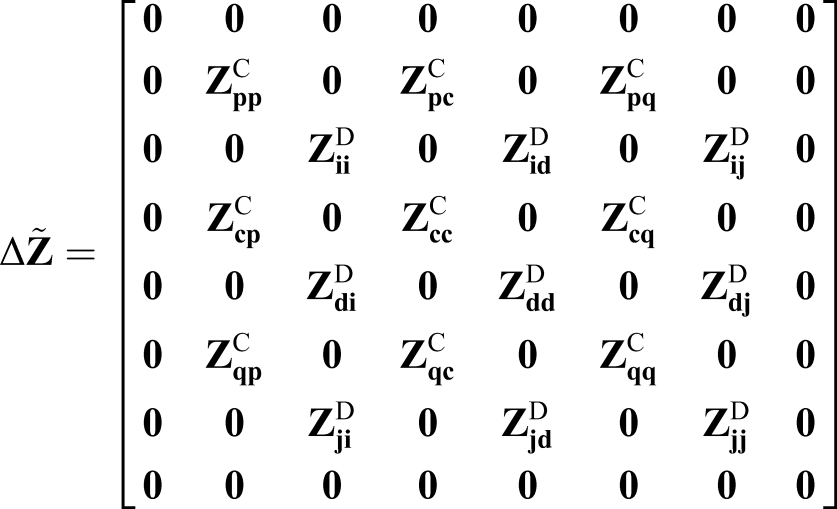
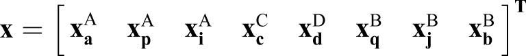
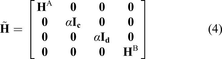
In equation (3),
Define a receptance-related matrix
Then, equation (3) is pre-multiplied by this matrix

Equation (5) would have solutions only if

The above equation could be simplified as
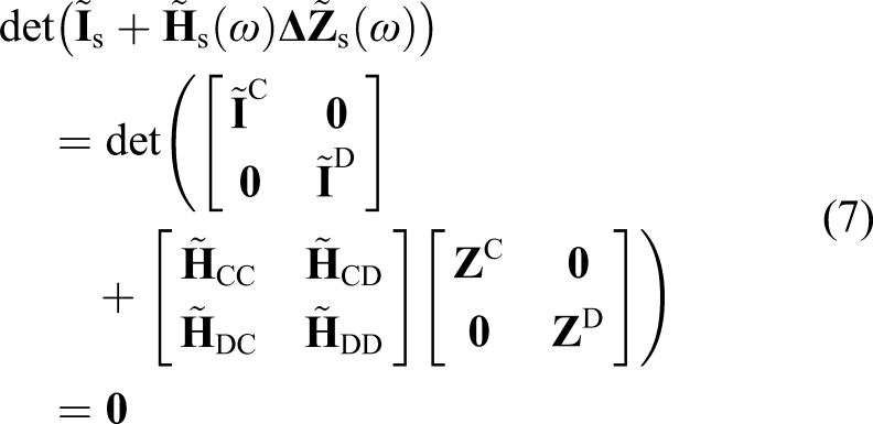
Detailed derivations from equation (6) to (7) could be found in Appendix 1. It should be noticed that the number of rows or columns in the matrices in equation (6) is the total number of DoFs of the assembled structure, which is usually very large in practice, whereas the number of rows or columns in the matrices in equation (7) is the number of DoFs of the connection DoFs between substructures A and B together and links C and D together, which is much smaller.
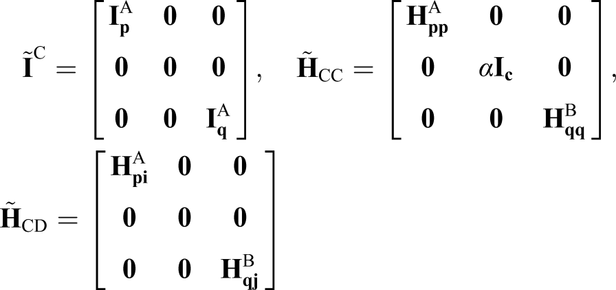
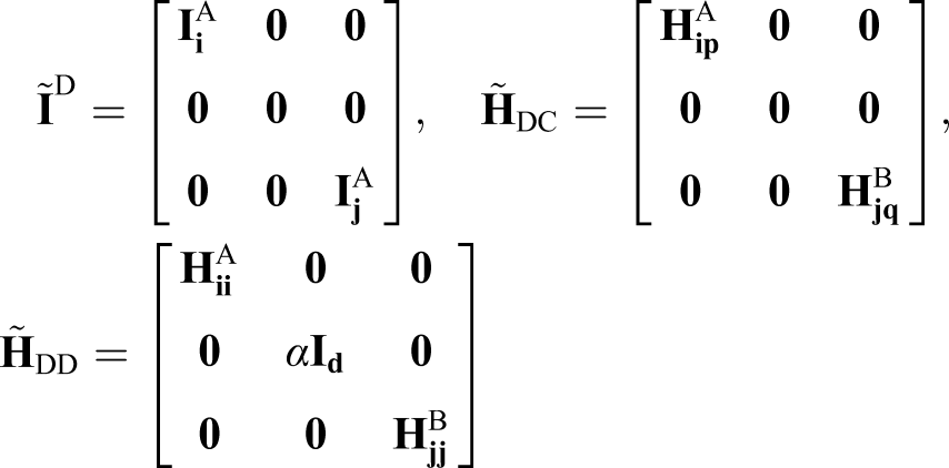
In equation (7),
Here,
Suppose that there is only one link C in Figure 1, equation (7) would be recast as

Similarly, if there are n independent links (that is they do not have shared DoFs), denoted by
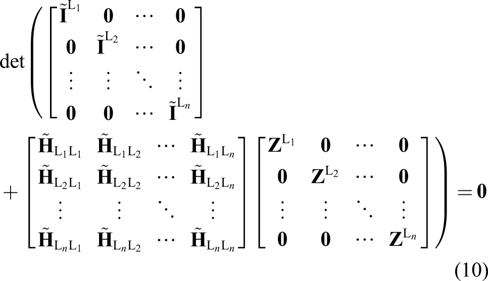
Therefore, this method could be applied to frequency assignment of assembled structure with any number of links. This receptance-based method does not require the system models of substructures. Only receptance matrices of substructures at the connection DoFs are needed and they are easier to be measured compared with mass matrices and more importantly, stiffness matrices.
3. Numerical simulation
In this section, two simulated examples are analysed using the proposed method in Section 2. The first example has two discrete substructures, which are to be connected using a spring–mass–spring link. The second one is about two frame structures connected through four beams. Damping is not considered in either example. In the following simulations, the required receptances are obtained from theoretical models. However, they will be directly measured in practice.
3.1. Discrete structure with one discrete link
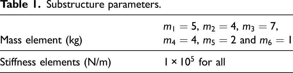
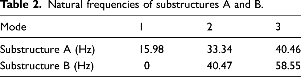
Two discrete substructures A and B are connected using a spring–mass–spring link, as shown in Figure 3. The parameters of these substructures are given in Table 1. Table 2 shows the natural frequencies of substructures A and B. It is required to assign a frequency Substructures A and B coupled through link C. Substructure parameters. Natural frequencies of substructures A and B.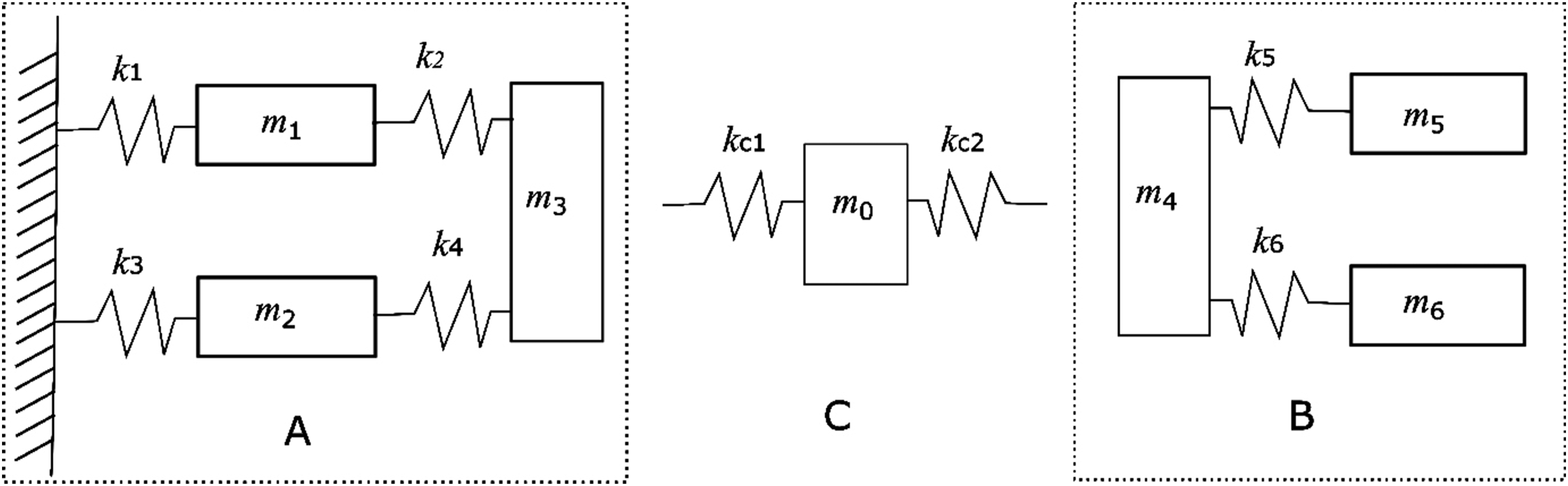
In this example, link C takes the form of spring–mass–spring, as shown in Figure 3. Suppose the parameters of this link are denoted by 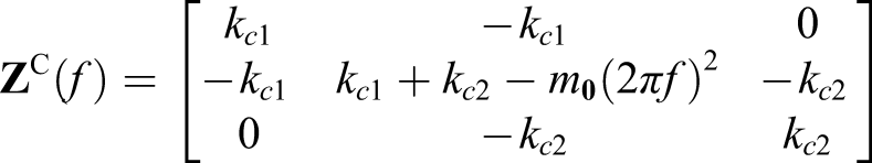
The receptance matrix at the desired frequency value is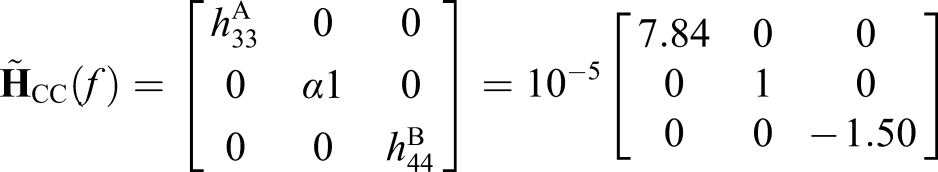
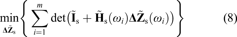
According to equation (9), the optimisation problem in this example would be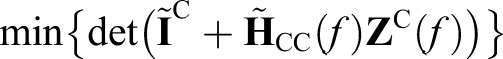
This optimisation problem can be solved using MATLAB built-in function fmincon. If
Figure 4 shows the frequency response function Frequency response function 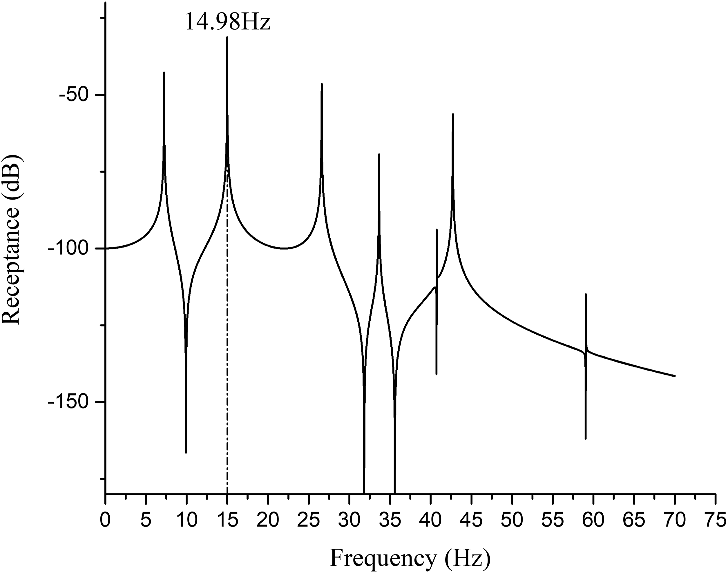
3.2. Continuous structure with multiple continuous links
Consider two frame structures A (in dark colour) and B (in light colour), which are composed of mild steel beams, are connected by four links at the midpoints of their four sides. Frame B is placed at the centre of frame A. The corresponding finite element models are shown in Figure 5. The finite element model of frame A has 14 nodes and six beams with two of them grounded. The finite element model of frame B has 12 nodes and four beams. Each node has 3 DoFs (a horizontal translation and a vertical translation and a rotation). The material properties of frames A and B and links C are the same. Young’s modulus is 210 GPa and the density is 7850 kg/m3. The cross-sectional areas of frames A and B are described in Table 3. The four links consist of two horizontal beams and two vertical beams. The cross-sectional areas of those link beams are optimised to assign (1) one natural frequency Finite element model of frames A and B and links. Cross-sectional areas of frames A and B.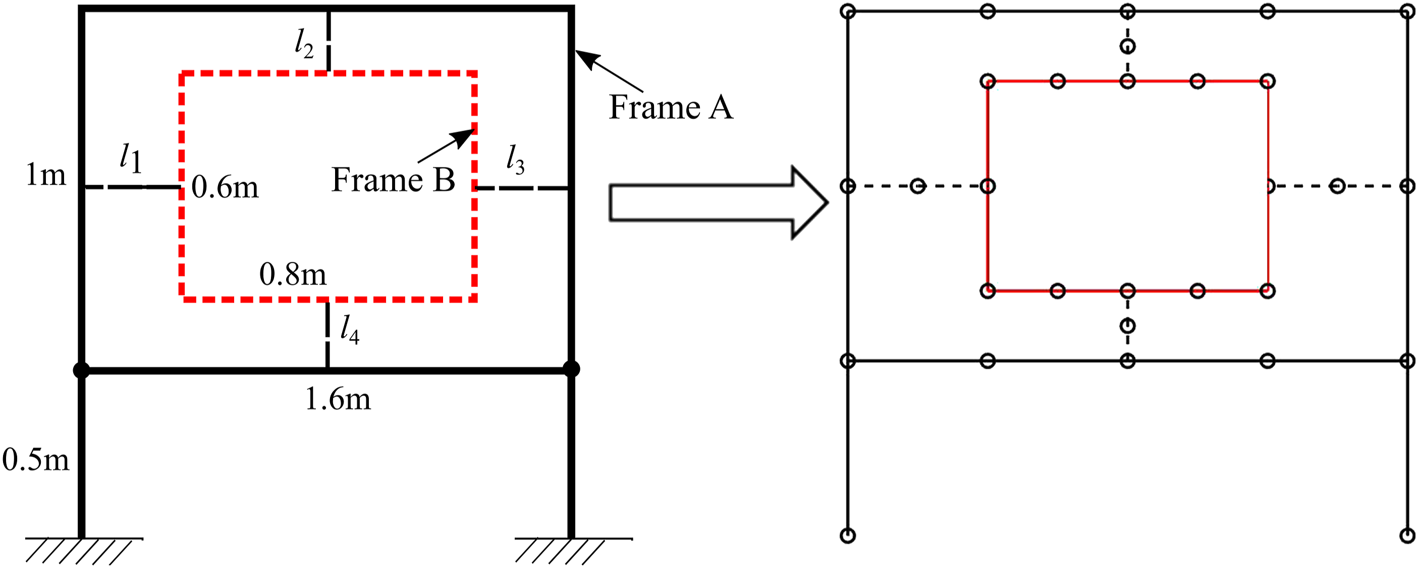
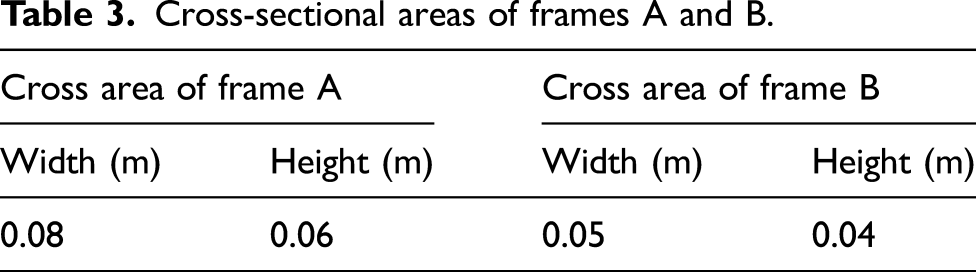
In this example, the lengths of those links are prescribed. The cross-section shapes of the four links are square and the design variables are the heights (or breadths) of these cross sections, which are denoted by
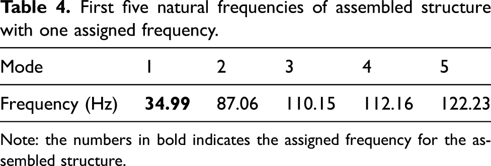
For the first problem, assuming Frequency response function First five natural frequencies of assembled structure with one assigned frequency. Note: the numbers in bold indicates the assigned frequency for the assembled structure.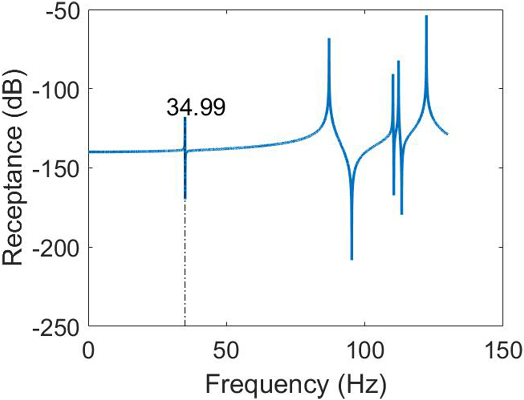
In the second problem, two frequencies are to be assigned to the assembled structure. Let Frequency response function First five natural frequencies of assembled structure with two assigned frequencies. Note: the numbers in bold indicates the assigned frequency for the assembled structure.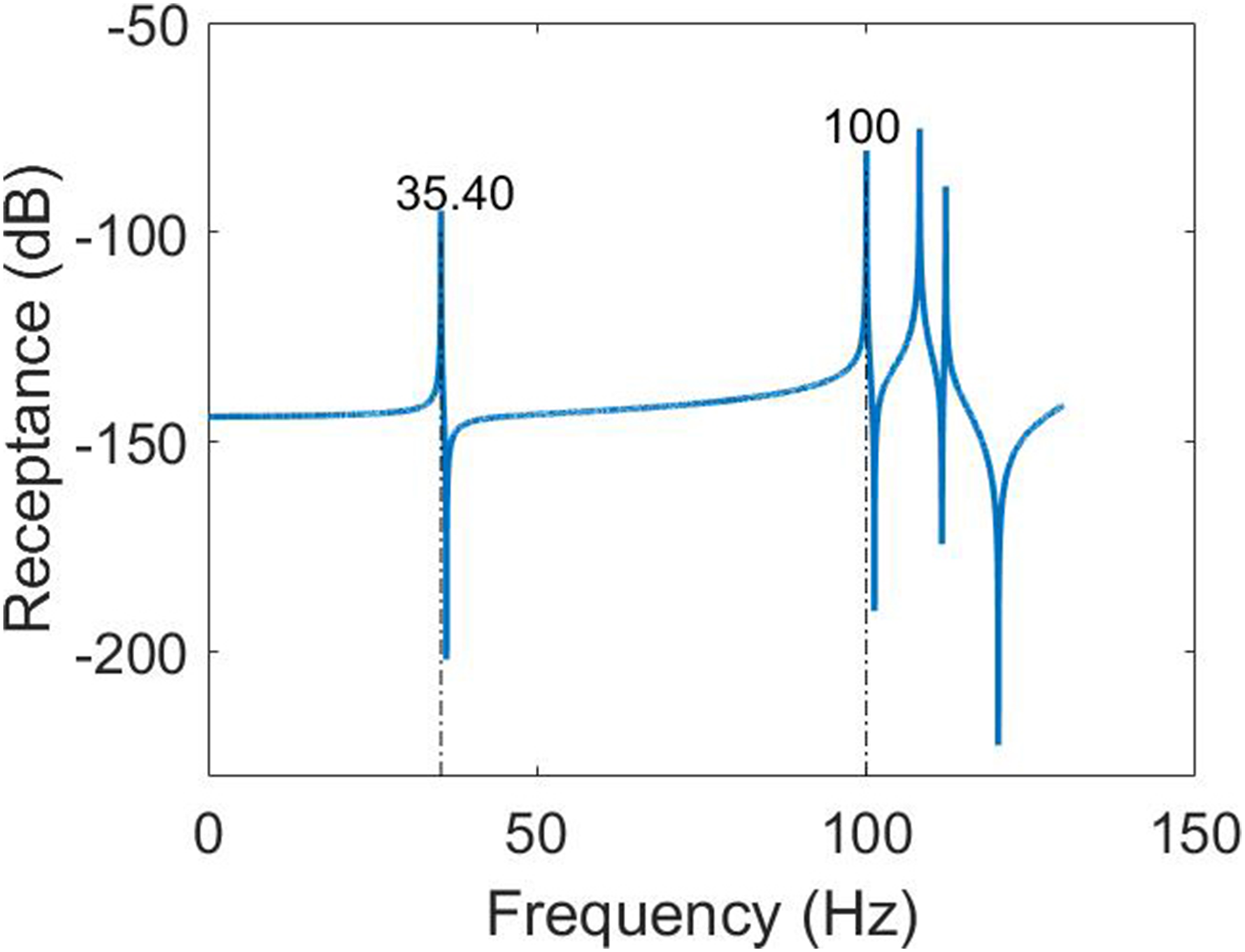
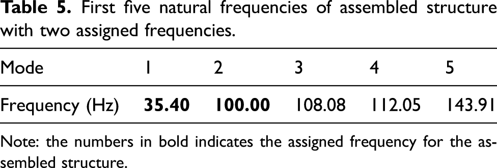
First five natural frequencies of assembled structure with two assigned frequencies.

Note: the numbers in bold indicates the assigned frequency for the assembled structure.
3.3. Discussion
In the above examples, there are usually more than one solution for each assignment problem. As shown in Section 3.2, there are two different solutions with different lower bounds and upper bounds. Although both solutions could assign the desired frequencies, the actually assigned frequencies correspond to different modes in the two solutions and thus the resulting assembled structures will have different dynamic behaviours. This is because mode shapes are not involved in this frequency assigment method, unlike a previous method reported in Ouyang et al. (2012). Therefore, a further optimisation, determining which solution is optimal among a number of feasible solutions that all assign the desired frequencies should be useful. This optimal solution could be determined based on other specific requirements, such as the restrictions on the parameters of links, or the corresponding mode shapes, as constraints to the optimisation problem described in equation (8). However, this work is beyond the scope of this study and will be studied in future.
One drawback of this method is that it requires the theoretical models (usually finite element models) of the links. However, this is unavoidable for an inverse assignment method because the modifications are unknown and cannot be measured beforehand. A theoretical model allows its frequencies to be associated with its structural properties and thus can be used in the optimisation algorithm used, which requires a repeated use of the theoretical model with different structural properties in the iterations. For simple links, such as mass–spring systems, beams or rods, it is quite easy to build theoretical models for them. On the other hand, it is difficult to model complex links accurately. However, the links are usually much simpler than the uncoupled substructures. Their possible lack of modelling accuracy would not have a big impact on the accuracy of frequency assignment, in the context of very complicated assembled structures. There are ways to reduce the inaccuracy of the theoretical models of complex links. For example if a link is to be a complex structure, then one can divide the link into modificable parts and unmodificable parts. The unmodificable parts could be measured by building real structures for them so that those structures would become another substructures. The modificable parts should be as simple as possible. It would be easier to build accurate theoretical models for these simple modificable parts. Engineering applications of this method will be investigated in the near future.
4. Conclusions
This study presents a receptance-based frequency assignment method for assembled structures. This method maintains the original substructures designed for specific requirements, and the assignment is achieved through modifying the links that connect the uncoupled original substructures. Those added links can be discrete structures or continuous structures. This method only requires the receptances of the uncoupled substructures at the connection points of the links which can be measured accurately and easily in practice, and the theoretical models of links which are usually much simpler than the uncoupled substructures are thus are easy to build and accurate.
Assigning frequency for an assembled structure using this method involves multiple substructures. The modifications in this study, as links, introduce extra DoFs for the whole assembled structure. The proposed methodology works well for any number of links and substructures. Two numerical examples are presented to validate this proposed method.
Footnotes
Acknowledgements
The first author is grateful to Dr Sung-han Tsai and Prof Jiafan Zhang for the helpful discussions and for the support of University of Liverpool in the form of a PhD scholarship.
Declaration of conflicting interests
The author(s) declared no potential conflicts of interest with respect to the research, authorship, and/or publication of this article.
Funding
The author(s) received no financial support for the research, authorship, and/or publication of this article.
Appendix 1
The simplification process from equation (6) to (7) is discussed here in detail. Equation (6) indicates that frequency assignment could be achieved if
This equation could be expanded as
It can also be rewritten as
According to the Leibniz formula for determinants, this equation equals to
Because the matrix determinant would not change by swapping rows and columns, equation (14) could be recast as
Then, it could be reformed as
In a compact form