
Abstract
Carbon–carbon composites are unique materials consisting of carbon fibers embedded in a carbonaceous matrix. Drilling of carbon–carbon composites is difficult to carry out due to the anisotropic, high specific stiffness and brittleness, nonhomogeneous inner structure of composites, and high abrasiveness of their reinforcing constituents. These typically result in defects being introduced into the workpiece and in very rapid wear development in the drilling tool. Defects are the undesired effects of machining using nonappropriate drilling parameters or worn drill. Aimed at this issue, first, the major defects caused in drilling needle-punched carbon–carbon composites are analyzed in detail. Second, the fiber fuzz factor and the ripping factor of fibers are defined to depict the drilling defects. Experiments are carried out using a conventional twist drill, and the results indicate that material structures, federates, and cutting speeds are reckoned to be the most significant factors contributing to defects.
Introduction
Carbon fiber–reinforced carbon matrix (C-C) composites are unique materials possessing exceptional high heat resistance, along with lightweight, high resistance to corrosion, high stiffness, and high strength. 1 C-C composites retain room temperature properties to more than 3000 °C in the inert atmosphere; this is the main trend of the development of high-temperature structural materials in the future. 2 Due to these special characteristics, they are widely used in aerospace field, mainly applies to aircraft braking systems and solid rocket nozzle. In addition, C-C composites are capable of applying to replace heart valves and hip due to their excellent biological compatibility. 3
Machining of C-C composites is a complex area, especially as companies are keen to keep their knowledge under secrecy. However, although conventional machining practices, such as turning, drilling, and milling, are a problem as the fibers and fiber direction result in an uneven cutting force and high tool wear, these still can be applied to the machining of C-C composites. Drilling with a twist drill is a fast and effective hole-making method for secondary machining of composite structures. However, being nonhomogeneous, anisotropic, high specific rigidity and brittleness, and reinforced by carbon fiber, C-C composites are difficult to drill. Defects and significant damages to the workpiece may be introduced, and high wear rates of the drills are experienced, as shown in Figure 1. Poor hole quality is the cause of nearly 60% of all components that are discarded. 4 Since drilling is often one of the final machining operations, a damage occurring at this stage causes huge economic losses when almost finished parts need to be rejected.
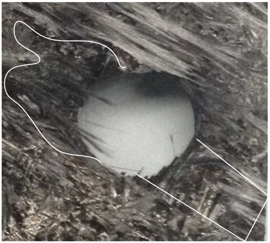
Failure hole of C-C composites.
Although decades have passed since C-C composites appeared for the first time, there is lack of study focusing on drilling technology of C-C composites. Jiang et al. 5 investigated the turning of C-C composite airplane brake plates. And they proposed YG8 as the best tool material, based on the tool wear rate of the rake face and/or flank. Ferreira et al. 6 used ceramics, cemented carbide, cubic boron nitride (CBN), and polycrystalline diamond (PCD) to research the turning process of C-C composites. Their experimental results showed that PCD was the optimal tool in finish turning, and cemented carbide tools could be used in rough turning with appropriate cutting parameters. Li et al. 7 proposed that the ultrasound-assisted milling relative to the normal milling could improve the surface quality of C-C composites, lower cutting temperature, and reduce the cutting force and tool wear. Also, it is helpful to process composites with high precision, high efficiency, and low cost.
Delamination is one of the undesired effects in drilling composites using nonappropriate drilling parameters or worn drill and has received extensive attention in the literature. In drilling of composites, most researches focus on carbon fiber–reinforced plastic (CFRP) composites. The most important contributions in drilling for composite laminates are summarized in a recent review4,8 including techniques, tools, and operations developed to minimize the occurrence of delamination. Delamination in CFRP composite laminates was correlated by multiple linear regression techniques relating cutting speed and feedrate with the delamination. Chen 9 proposed a concept of delamination factor to analyze and compare the delamination degree in drilling of CFRP composite laminates. The delamination factor is defined as the ratio between the maximum diameter of the damage zone and the nominal hole diameter. His experimental results showed that delamination-free drilling processes may be obtained by the proper selections of tool geometry and drilling parameters. Moreover, traditional and nontraditional drilling processes are feasible for making fine holes for composite materials by carefully selected tool, method, and operating conditions. 10 Tsao 11 investigated the effects of drilling parameters on induced delamination for various step-core drills by an experimental method. Thereafter, Tsao and Wu 12 proposed a fuzzy decision-making trial and evaluation laboratory method to evaluate the causal influence of the various tool materials and geometries, as well as machining parameters, in drilling composites using compound special-core drills. Davim and Reis 13 found that error associated with the delamination factor has excellent correlation using experiments. Thereafter, Davim et al. 14 presented a technique to measure the adjusted delamination factor based on a digital image analysis method. Their experimental results indicated that the use of digital analysis is suitable to estimate the damages produced after drilling CFRP. Zhang et al. 15 investigated the effects of drilling parameters on induced delamination and fuzz in drilling of CFRP using a scanning acoustic microscope. Mohan et al. 16 employed a signal-to-noise ratio to analyze the influence of cutting speed, feedrate, drill size, and specimen thickness on peel up and push down delamination factor in drilling of glass fiber–reinforced plastic (GFRP) composite laminates. Their experimental results showed that the use of high cutting speed and low feedrate favor the minimum delamination on both entry and exit of the drilling leads to better surface finish and tool life.
Wang et al. 17 found that the orbital drilling method can suppress defects at the exit in drilling of carbon/epoxy (C/E) composites because the cutting temperature is much lower than the conventional method. Brinksmeier et al. 18 found that high cutting speeds lead to increasing borehole surface layer damage in the CFRP. Their experimental results showed that the surface integrity at boreholes in aluminum-CFRP-titanium generated by orbital drilling is better with respect to the CFRP quality than by conventional drilling.
Finite element modeling of the complex drilling process has been recently achieved in Phadnis et al. 19 and Isbilir and Ghassemieh. 20 In these works, drilling of CFRP was successfully reproduced including drill penetration in the workpiece, material failure, and elements erosion. Thereafter, Feito et al. 21 developed and compared the complete and simplified models in terms of delamination prediction in CFRP drilling. The simplified model, presenting reduced computational cost, slightly overestimates the delamination factor when compared with the complex model. Rahmé et al. 22 developed an orthotropic analytical model to calculate the critical force of delamination during drilling. This critical axial load is related to the delamination conditions of the last layers and the mechanical characteristics of the composite material machined. The material used by Rahmé et al. is a thick plate of carbon epoxy (T800/M21) comprising 80 layers with a quasi-isotropic layering sequence.
It can be seen from the review of literatures that most previous researches on drilling defects have been concerned with CFRP or GFRP, only few work was paid attentions on C-C composites. Since the surface quality plays an important role in the improvement of fatigue life of composite components, 23 it is necessary to improve the drilling quality and efficiency of C-C composites.
The remainder of this article is organized as follows: in section “Defect analysis caused by a twist drill,” the reason of defects caused by a twist drill in drilling C-C composites is analyzed; in section “Quantization of defect in drilling of C-C composites,” both the fiber fuzz factor and the ripping factor of fibers are quantized in detail; machining experiments are conducted in section “Description of experimental work”; experimental results are discussed in section “Results and discussion”; and conclusions are given in section “Conclusion.”
Defect analysis caused by a twist drill
The C-C composite workpiece used in this article is produced by laminating the nonwoven fabrics and chopped carbon fiber felt one over another and subjecting the laminated nonwoven fabrics to needle punching repeatedly with a plurality of needles, thereby yielding a fabric body of three-dimensional structure and carbonizing the thus obtained fabric body by chemical vapor infiltration (CVI) method with vaporized kerosene as a precursor. The microstructure of this C-C composite with needle-punched felt is shown in Figure 2.

Structure of the needle-punched C-C composite.
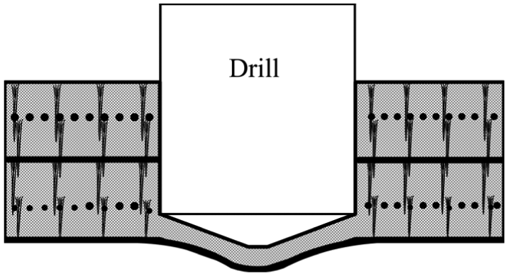
Although this material is reinforced by needle-punched felt, it is quite weak in the needle-punched direction and is easily crushed. The drilling direction discussed in this article is perpendicular to nonwoven fabrics. The analytical approach applied to drilling is based on a number of assumptions. Cracks are assumed to be due to the pressure of a drill on the last layer. As shown in Figure 3, when the drill approaches the hole exit, the rigidity of the undrilled layer becomes lower and lower because the thickness of remaining material is gradually being decreased. This may lead to a flexure deformation and fracture of the undrilled layer under the thrust force of the drill. Hence, some defects, such as fiber fuzz, matrix crushing, and ripping of fibers, may appear at the exit edge. Obviously, defects appeared at the exit are mainly caused by the thrust force of the drill. To analyze the defects caused by thrust force, several assumptions are introduced for the drilling model:
Fibers of nonwoven fabrics are distributed uniformly, and tensile strengths of all fiber bundles are a same constant value.
Chopped fiber felts and matrixes are mixed uniformly and can be regarded as isotropic material.
The thrust force of a drill being applied on the undrilled layer is decomposed into two types of uniformly distributed loads, q 0 and q 1, as shown in Figure 4. They are caused by the chisel and cutting edge of the drill, respectively.

Thrust force on the undrilled layer.
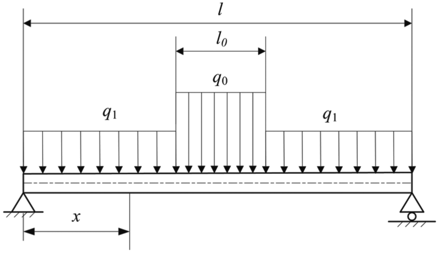
Two uniformly distributed loads on a simply supported beam.
The flexure deformation of a cross-section of the workpiece looks like a variable-thickness arch before the hole is finished, as shown in Figure 5. Hence, the last undrilled layer under the thrust force of a drill can be simplified as a simply supported beam, as shown in Figure 4. Its flexure deformation under two types of uniformly distributed loads, q 0 and q 1, can be expressed by equation (1)

Flexure deformation of the last undrilled layer.
If cutting parameters are not appropriate in drilling a through-hole, cracks may occur on the last undrilled layer due to the influence of thrust force when the hole is nearly finished. Cracks are more easily extended at the bonding surface of chopped fiber felts and nonwoven fabrics.
With continuously drilling, the chisel edge of the drill moves out from the last layer first. The residual part which has not been cut off in time can be considered as a cantilever beam structure, as shown in Figure 6. Its stiffness is much lower than before.
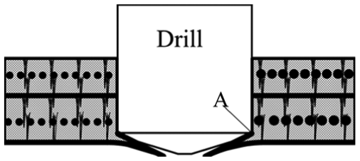
Deformation of the residual part after the chisel edge drilling out.
As shown in Figure 6, point A is a connection point between the residual part and the hole wall. If the breaking intensity of the material at this point is larger than the thrust force, the residual part can still be cut off, and no defect would be emerged at the exit edge. However, if not, it may be bent under the thrust force, and cracks may emerge, resulting in matrix crushing and ripping of fibers.
Different shapes of the last layer may lead to various defects in drilling C-C composites as follows:
When the last layer is chopped fiber felt. When matrices are crushed by the thrust force, chopped fiber felt may not be cut off from the hole edge properly, and this is called small fiber fuzz.
When the last layer is nonwoven fabric. On one hand, fabrics may lose bonding with matrix and chopped fiber felt under the thrust force near the hole edge, and this is called ripping of fabrics. Ripping of fabrics and matrix crushing always act and react upon each other. Comparing with CFRP, the breaking intensity between the nonwoven fabric and chopped fiber felt of C-C composites is strengthened by needle-punched felts. Hence, cracks are not easy to extend and do not lead to widespreaded lamination as CFRP. On the other hand, the outermost side fabrics may be stretched to the limitation and prematurely fracture before being cut off. The residual fibers which should be cut off are called large fiber fuzz.
Quantization of defect in drilling of C-C composites
Calculation of the fiber fuzz factor
According to diameter dimensions, fiber fuzzes can be classified into two types: small fuzz and large fuzz. Fiber fuzzes less than 0.2 mm in diameter or width are called small fuzz; the others are called large fuzz. Small fuzzes are always found in the front of large fuzzes or next to them and have no effect on the assembly. Generally, small fuzzes can be measured by length. However, large fuzzes should be measured by area instead of length because if the width is ignored, the influence of large fuzzes will be weakened.
Hence, the small fuzz factor can be calculated using equation (2) based on the nominal circumference of the hole

where d is the nominal diameter of the hole and li is the length of the ith small fuzz.
The large fuzz factor can be calculated using equation (3) based on the nominal area of the hole

where Si is the area of the ith large fuzz.
Small fuzzes and large fuzzes always occur together. Therefore, the global fuzz factor of a hole should be calculated as follows

where both α and β are weights, α + β = 1. Because small fuzzes have little effect on the assembly, α is set as 0.9 and β as 0.1 in this article.
Calculation of the ripping factor of fibers
Ripping of fibers often exists at a hole exit edge, and fiber fuzzes often appear with ripping of fabrics. Ripping of nonwoven fabrics always expands in a large transverse region, but a small depth roughly equaling to the thickness of one-layer nonwoven fabric. The length, width, and depth of defects can be measured by X-ray computed tomography (CT). Therefore, the ripping factor can be calculated based on these measured data.
The ripping factor of nonwoven fabrics can be defined by defect areas. An acceptable defect area should be within the area of a rectangle whose length is three times the nominal hole diameter, and width is 1.8 mm according to China Aviation Academy, 24 as shown in Figure 7. Hence, the ripping factor of nonwoven fabrics can be calculated by equation (5)


Region of ripping damage at the hole exit.
where Si is the area of the ith ripping area of nonwoven fabrics and η m is the thickness ratio of nonwoven fabrics to the sum of nonwoven fabrics and chopped fiber felts.
Matrix crushing may cause a large-sized defect if it occurs on chopped fiber felts. Matrix crushing on chopped fiber felts has a little extension along the transverse region but a large extension along the height direction, as shown in Figure 8. An acceptable critical value of matrix crushing is relative to the drilled hole diameter according to China Aviation Academy, 24 as shown in Table 1. The length and width of matrix crushing can be extremely accurately measured by microscopically magnifier or other equipments. Moreover, in some cases, it can be observed and measured by naked eyes combined with a transparent grid plate. Its depth can be measured by CT.

Matrix crushing defect region of composites at the hole exit.
Critical values of matrix crushing defects at a hole edge in drilling composites.

Hence, matrix crushing factor in chopped fiber felts can be expressed as follows

where hi
is the maximum vertical depth of the ith matrix crushing region, h
max is the maximal critical depth value of matrix crushing,
In most cases, the exterior surface of C-C composite components after secondary machining is not an exactly single nonwoven fabric structure or single chopped fiber felt structure, but a mixture structure of nonwoven fabric and chopped fiber felt normally, as shown in Figure 9. Hence, both the ripping factor and matrix crushing factor must be considered together when calculating the ripping factor of fibers. The global ripping factor of fibers should be calculated as follows


Mixture structure of chopped fiber felt and nonwoven fabric.
Description of experimental work
The workpiece used in this article is a needle-punched C-C composite. The carbon fiber preform is fabricated with the three-dimensional needling method. The carbon fiber utilized is T300. The thickness of the workpiece is 6 mm. The thickness ratio of chopped fiber felts to nonwoven fabrics is about 1:3. The fiber volume fraction is about 25%. The void rate is about 10%, and the density is about 1.73 g/cm3. For impregnating carbon fibers with a matrix in the form of hydrocarbon gas, CVI is used in the preparation of C-C composites. The mechanical properties of the workpiece are shown in Table 2. It can be seen that interlaminar shear strength of this type of C-C composite is far less than transverse tensile strength.
Mechanical properties of the workpiece.

Experiments are carried out in a YHVT-850 computer numerical control (CNC) three-axis machining center. The twist drills are 6 mm in diameter. The material of the twist drills is K40 carbide. The point angle is 160°, the helix angle is 40°, and the rake angle is 120°. Thrust forces are recorded using a Kistler force-measuring platform connected to a charge amplifier. The force signals are transmitted to a computer and analyzed using the DEWESoft software. Two inspection methods are used in evaluating defects: optical microscopy and CT. Optical inspection is performed using leica S6D. CT inspection is performed using an industrial metrology CT system with a 120-kV X-ray source, 2.5-μm minimum focal spot size, and flat panel detector with 1024 × 1024 pixels at 8 bit. The drilling parameters are given in Table 3. Figure 10 shows the actual drilling process.
Drilling parameters.


Drilling process.
Results and discussion
Effect of drilling parameters on fiber fuzzes
All the entrance and exit edges of the drilled holes are inspected first using leica S6D. The inspection results show that there are only a little of small fiber fuzzes at the entrance edges of holes. All the fiber fuzzes at the entrance edges are less than 50 μm, as shown in Figure 11. This type of fiber fuzz has no effect on the assembly and can be accepted in industry.
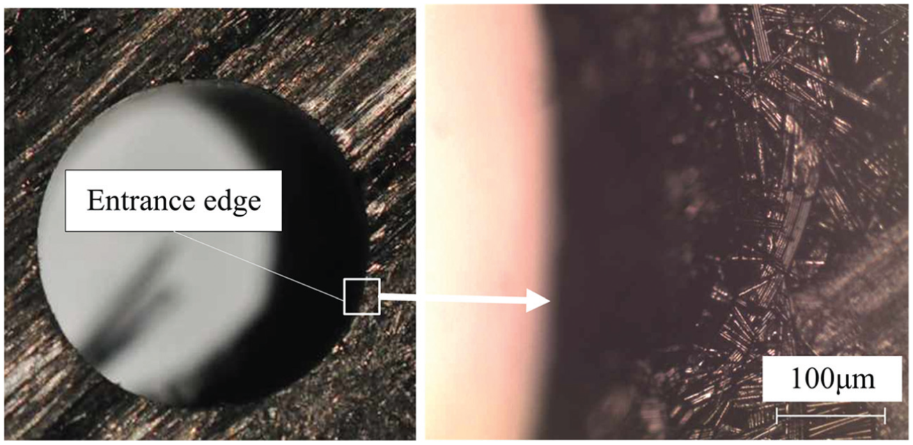
Fiber fuzzes at the entrance edge.
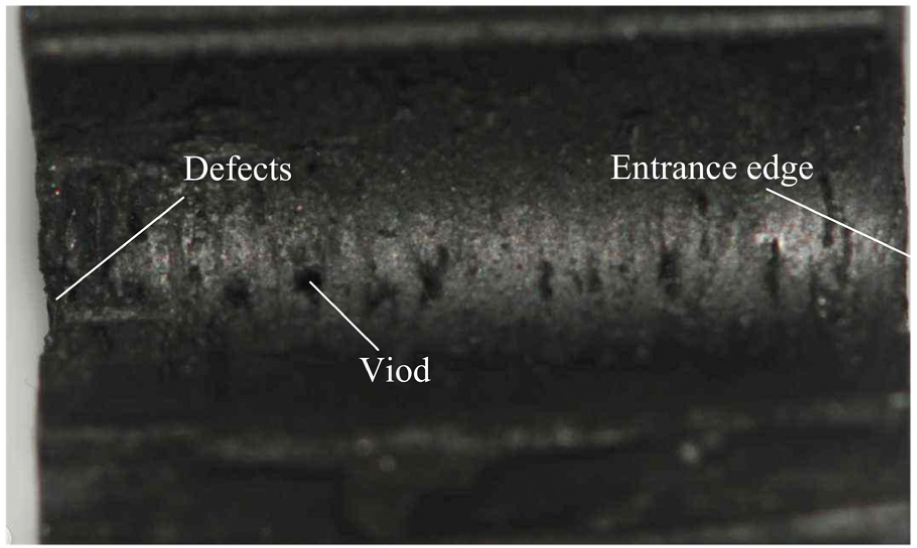
However, unlike the entrance edges, many fiber fuzzes exist at the exit edges of holes, as shown in Figure 12. It can be seen that large and small fuzzes occur together.

Fiber fuzzes at the exit edge.
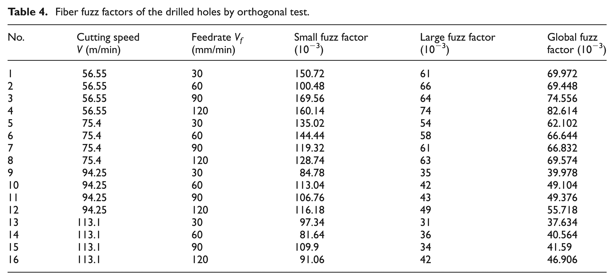
The fiber fuzz factors are calculated using equations (2)–(4) according to the measured results, as shown in Table 4. It can be seen from Figure 13 that the global fuzz factors increase slowly with the increase in the feedrate and decrease gradually as the spindle speed increases in the testing range. Two possible reasons lead to this phenomenon: the first one is that with the increase in the cutting speed, the cutting force decreases and the fiber is easier to be cut off by a sharp cutting edge. Another reason should be that with the increase in the feedrate, the thrust force increases greatly, but the force for fiber cutting increases slowly.
Fiber fuzz factors of the drilled holes by orthogonal test.
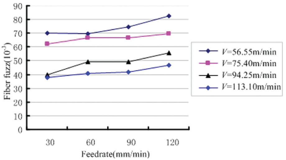
Global fuzz factors versus drilling parameters.
Figure 14 shows the influence of drilling parameters (cutting speed and feedrate) on large and small fuzz factors. The large fuzz factors increase slightly with the increase in the feedrate and decrease with the increase in the cutting speed. It is similar to the changing pattern of the global fuzz factors. The small fuzz factors decrease gradually with the increase in the cutting speed, but they are negligible affected by the feedrate. The experimental results show that it is beneficial to increase the cutting speed appropriately in drilling C-C composites because the fiber fuzzes can be weakened at the exit edge.

Two types of fuzz factors versus drilling parameters.
Effect of drilling parameters on the ripping of fibers
The ripping of nonwoven fabrics and matrix crushing always occur together, as shown in Figure 15. The ripping factors of nonwoven fabrics and matrix crushing are calculated using equations (5)–(7), respectively, as shown in Table 5.

Defects of a drilled hole: (a) matrix crushing and (b) ripping of nonwoven fabrics.
Ripping factors of the drilled holes.

Figure 16 shows that the ripping factors of fibers increase with the increase in the feedrate and cutting speed. The ripping factors change gently when they are <0.7. Once they are >0.7, the ripping factors change quickly. The results indicate that the feedrate is the major factor causing ripping of fibers in drilling C-C composites. The main reason is that the thrust force will increase as the feedrate increases when the cutting speed is not changed. When the feedrate is very low, the thrust force is too small to overcome the strength of the undrilled layer. Hence, in this case, cracks are difficult to extend, and the ripping of fibers is gentle. On the contrary, when a fast feedrate is given, the thrust force will increase heavily, and cracks’ extensions are large. In this case, following the matrix crushing, a great deal of ripping of fibers emerges.

Ripping factors versus drilling parameters.
The use of CT scanning and sweeping a plane around the reconstructed hole makes it much easier to cover larger volumes in the inspection examining both surface and sub-surface defects simultaneously and thereby making sure that the complete volume of interest is covered. Scan slice thickness of CT used in this article is 0.127 mm. Figure 17 shows the typical slice images of the drilled holes. The number in the center of images is the slice layer number. The No. 1 image is the first slice at the exit of the drilled hole. The No. 55 image is the last slice at the entrance. The shaded regions which scale out of the nominal shade circle in the first to third slices are the ripping regions at the exit edge. The area of each ripping region can be calculated according to the slice images. Assume that there are n slices continually containing the shade of the ith ripping region. Then, the depth of the ith ripping region can be calculated by equation (8) according to the slice thickness and the amount of slices


Slice images of a drilled hole by industrial metrology CT.
where H is the slice thickness and n is the amount of slices containing the shade of the same ripping region.
Figure 17 shows that most of the slices have some small partial shades which scale out of the nominal shade circle. These shades are distributed at random. To analyze them, this hole is split along the central axis line section, as shown in Figure 18. Figure 18 shows that there are many different sizes of voids distributed randomly on the hole wall. Voids did not form in the drilling process but in the preparation of C-C composites.
Section of drilled hole.
Conclusion
C-C composites are advanced composites with superior thermal properties. They are currently the ultimate materials for brakes and other high-performance applications. The machining process, especially drilling, is difficult as damage always appeared. In this article, the defects caused by a conventional twist drill are analyzed in detail, and the defect factor is defined and used in investigating drilling defects.
The following conclusions are found from the verification experience:
The major drilling defects at the hole exit of C-C composites can be classified into two types: fuzz and ripping. Crush of carbon matrix and tearing of fabrics may cause failure of workpiece.
Material structures, federates, and cutting speeds are reckoned to be the most significant factors contributing to the defects.
Footnotes
Academic Editor: Pedro AR Rosa
Declaration of conflicting interests
The author(s) declared no potential conflicts of interest with respect to the research, authorship, and/or publication of this article.
Funding
This work was supported by the National Natural Science Foundation of China (grant no. 51105312) and the Fundamental Research Funds for the Central University of China (grant no. 3102015JCS05005).