
Abstract
Composite/metal stacks are widely used in aerospace structures. To study the mechanism of damage generation during drilling of carbon/epoxy composites and titanium alloy stacks, both traditional drilling and orbital drilling were used. Because the cutting parameters of the two drilling processes were different from each other, an appropriate comparing method was proposed based on the analysis of kinematics of orbital drilling and traditional drilling. The results show that high cutting temperature is the main reason for the damage generation during drilling of composite/titanium stacks. Cutting heat generated during machining of titanium alloy conducts to the composites and leads to the increase of composite temperature. High cutting temperature induces the degradation of carbon/epoxy composite properties, which results in the generation of damage during machining of composites. The cutting force in axial direction during orbital drilling is generally as high as that during traditional drilling. However, the temperature during orbital drilling is 36.3% less than that during traditional drilling. High cutting temperature and continuous chip generated during traditional drilling cause the high hole-wall roughness of titanium alloy. The lower temperature during orbital drilling is responsible for the machining quality of orbital drilling being higher than that of traditional drilling.
Keywords
Introduction
Carbon/epoxy composites and titanium alloy are used increasingly in aerospace, naval and automotive industries.1,2 In order to assemble composite and metal parts, bolt and rivet holes need to be produced in large numbers. To improve manufacturing process, holes are drilled through composite/metal stacks instead of drilling each composite and metallic material separately.
However, titanium alloy is one of the difficult-to-cut materials, and damages easily appear during traditional drilling of carbon/epoxy composites.3–6 For instance, the increase in the thrust force, the feedrate and the rate of wear of the tool is responsible for the generation of damages during drilling of carbon/epoxy composites.7–9 Besides, high thrust force is regarded as the main reason for the generation of delamination.10,11 These damages can lead to a reduction in fatigue strength and load-carrying capacity of composite structures. 12 Zitoune et al. 13 have pointed out that the tensile strength of the plates with moulded holes was 28% higher than that with drilled holes. During machining of titanium alloy, high cutting temperature is considered as an important factor. That is because high cutting temperature can lead to serious tool wear, which induces the decrease of machining accuracy.14,15 Moreover, the properties of carbon/epoxy composite, as well as the cutting parameter, are significantly different from those of titanium alloy.16,17 It is clear that drilling of composites and titanium alloy stacks is a challenging task.
During manufacturing and assembly operations for Boeing 787, drilling of composite/metal stacks is regarded as a key factor, which can decrease machining efficiency and increase manufacturing cost. 18 Tool materials and cutting parameters were investigated by many researchers to improve the machining quality of composite/metal stacks.19–21 Moreover, the influence of tool material on drilling performance of composite/metal stacks was studied by Zitoune et al. 22 and Park et al. 23 However, the mechanism of damage generation during drilling of composite/metal stacks needs further investigation.
Orbital drilling is a hole-making process by milling, and a milling tool rotates on a helical path and generates the borehole.24,25 As opposed to traditional drilling, it is considered that orbital drilling offers many advantages, for instance, low burr formation, low process forces, little delamination in composites and good chip transportation.26,27
In this article, two drilling processes, orbital drilling and traditional drilling, were used to verify the damage mechanism. Based on the analysis of kinematics of both orbital drilling and traditional drilling, a comparing method of the two drilling processes was proposed. And, carbon/epoxy composites and titanium alloy stacks were drilled. Cutting temperature, cutting force and machining quality were compared. The mechanism of damage generation during drilling of composite/titanium stacks was discussed. This work can give a useful understanding for the generation of damage during machining of either carbon/epoxy composites or titanium alloy and provide some guidance for drilling of composite/metal stacks.
Kinematics of orbital drilling and traditional drilling
In order to verify the damage mechanism during drilling, both orbital drilling and traditional drilling were used for machining carbon/epoxy composites and titanium alloy stacks. However, there is a significant difference between cutting parameters of the two drilling processes. Nevertheless, during discussion of orbital drilling and traditional drilling at present, cutting conditions used for the two machining processes were independent of each other. 28 For instance, cutting speed, machining efficiency and tool materials were different during comparison. As a result, an appropriate comparing method is needed to study the damage mechanism of the stacks when using the two drilling processes.
When tool material and workpiece are settled in an experiment, the cutting speed becomes the dominant parameter for the machining quality. Besides, the machining efficiency is an important factor during the selection of machining processes. Therefore, the cutting speed, machining efficiency and tool material should be same during comparison of machining processes.
The trajectory of cutting tool, as well as machining parameters, is different during orbital drilling and traditional drilling. During orbital drilling or traditional drilling, the motion of cutting tool can be decomposed into two parts: the motion parallel to the tool axis and the motion perpendicular to the tool axis. On the plane which is perpendicular to the tool axis, Figure 1 shows the motions of cutting tool. During orbital drilling, the velocity of tool edge vco can be calculated using the following equation
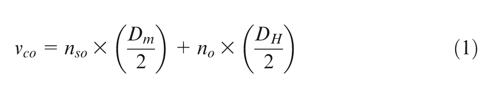
where DH is bore diameter, Dm is tool diameter, no is orbital speed, nso is spindle speed and vco is the velocity of tool edge. During traditional drilling, the velocity of tool edge vct can be expressed as
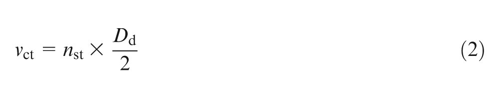
where Dd is tool diameter and nst is spindle speed.
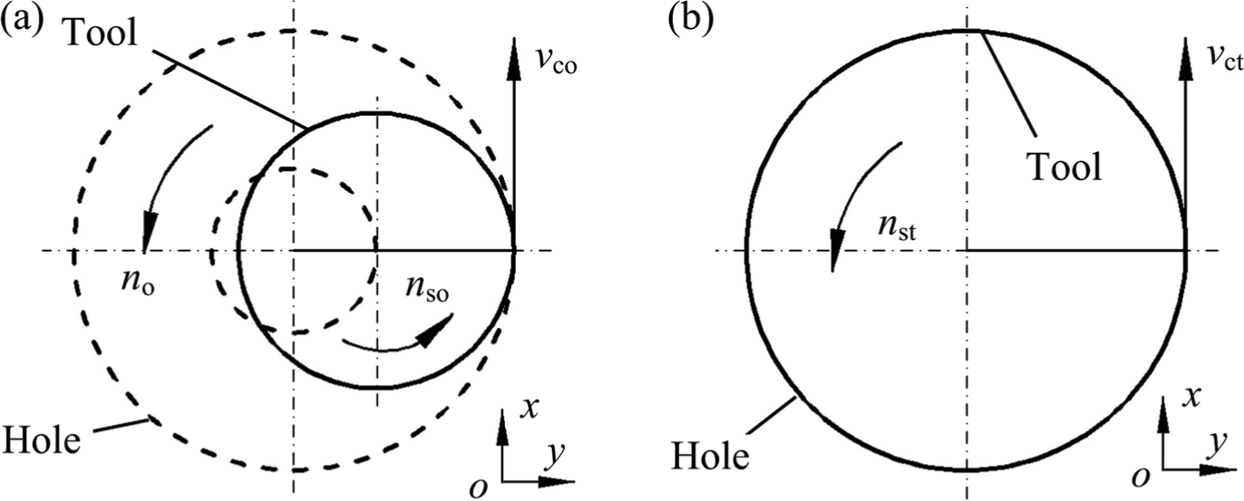
Motion of cutting tool on the plane perpendicular to the tool axis: (a) orbital drilling and (b) traditional drilling.
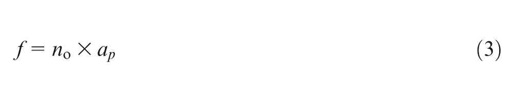
The motion parallel to the tool axis influences machining efficiency and thrust force. Machining efficiency is the processing time cost for making a hole. In this experiment, same machining efficiency means the speed of cutting tool in axial direction is same. Based on the analysis of the motion of cutting tool, when the machining efficiency is the same, the relationship between axial feedrate of orbital drilling and that of traditional drilling f can be expressed as
Experimental procedure
Selection of cutting parameters
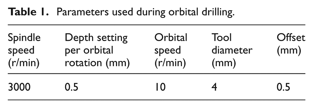
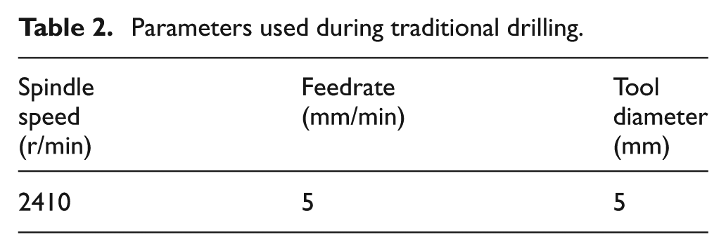
When both the cutting speed and the machining efficiency are the same, cutting parameters of the two machining processes can be calculated by equations (1)–(3). Previous orbital drilling tests were carried out to establish appropriate cutting parameters. From these tests, parameters used in orbital drilling are shown in Table 1. Then, parameters used in traditional drilling were calculated, as shown in Table 2. Bore holes with a diameter of 5 mm were machined. The drill of 5 mm in diameter with carbide and 118° point angle was used during traditional drilling. Because the cutting tool used in traditional drilling had two cutting edges, the tool used in orbital drilling was an end mill featuring two teeth (the material of the mill was carbide and the diameter was 4 mm). And, there was no coolant used during machining.
Parameters used during orbital drilling.
Parameters used during traditional drilling.
Experimental set-up
Composite material used in the experiment was made from the unidirectional prepregs (T300 carbon fibre in AG-80 epoxy matrix) using the autoclave manufacturing process. The lay-up sequence of the prepregs was [0°/90°/±45°]12s. The ramp rates were 3 °C/min for heating and 2 °C/min for cooling. The cure temperature was held at 177 °C for 2 h, and 700 kPa inert gas pressure was used during manufacturing. The thickness of the composites was approximately 5 mm, the fibre volume fraction was about 65% and the ply thickness was about 0.125 mm. The tensile modulus and the energy release rate in mode I (GIc) of carbon/epoxy composites used are about 75.88 GPa and 227 J/m2, respectively. The glass transition temperature of the composites is about 205 °C. The titanium alloy for the experiment was Ti-6Al-4V, and the specimens were approximately 4 mm thick. The chips were removed in process via a vacuum dust removal system.
A Kistler 9271A piezoelectric dynamometer was used to measure the thrust force during drilling. The force signals captured by dynamometer were sent to Kistler 5807A charge amplifiers and recorded on a personal computer subsequently. Besides, the temperature field during machining was captured by an infrared thermal imager.
Results and discussion
Machining temperature
The determination of temperature of tool–workpiece interface is not an easy process. 29 Several forms of experimental methods can be used for measuring the temperature during cutting process. 30 Usually, thermocouples or infrared devices are used in temperature measuring. Temperature at a location can be measured by a thermocouple. Thermocouple is often embedded in the tool to avoid disturbing the temperature field in workpiece. But due to the high-speed rotation of the drill, it is difficult to measure temperature during drilling. On the other hand, the manufacturing and the embedding of thermocouple are manual processes, which implies that the result is not stable.
Temperature field on the workpiece surface can be detected using an infrared thermal imager. The temperature in the material cannot be obtained by an infrared thermal imager, but the measuring result is relatively stable. And, if the detected surface is close to the cutting area, the measuring result may be regarded as the temperature around cutting area. In this experiment, a stability result was needed for comparing the two machining processes. Consequently, the variation in temperature field was detected by an infrared thermal imager. Although the measuring results were not actually the cutting temperature, the results still could be used for the comparison of cutting temperature.
The temperature distribution on the workpiece surface during machining was recorded (as shown in Figure 2). Then, the temperature at three positions (A: at centre middle of the thickness of carbon/epoxy composite, B: at the interface of two materials and C: at centre middle of the thickness of titanium alloy) during drilling was obtained. In this experiment, the distance between the infrared thermal imager and the specimen was 800 mm, and L was 3 mm, as shown in Figure 2.
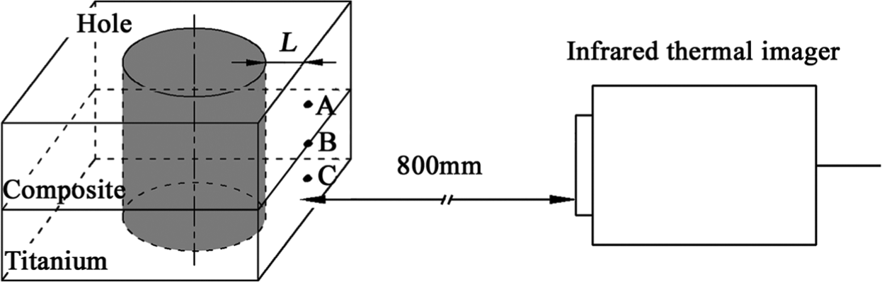
Position of specimen and the infrared thermal imager.
Figure 3 shows the variation of temperature during machining at different locations. Compared with the maximum temperature during traditional drilling, the maximum temperature during orbital drilling decreases more than 36.3% (as shown in Table 3). Cutting heat is mainly generated through plastic deformation in the primary shear zone, the friction of chip on the tool face and the friction between tool and workpiece. 31 During machining of titanium alloy, the high temperature is mainly due to the catastrophic thermoplastic shear process and the poor thermal conductivity. 32 However, there is little plastic deformation during machining of composites due to the brittleness of carbon fibre and the matrix. Accordingly, cutting heat is mainly generated from friction heat. And, friction heat results from the friction between soft matrix and fractured carbon fibres.
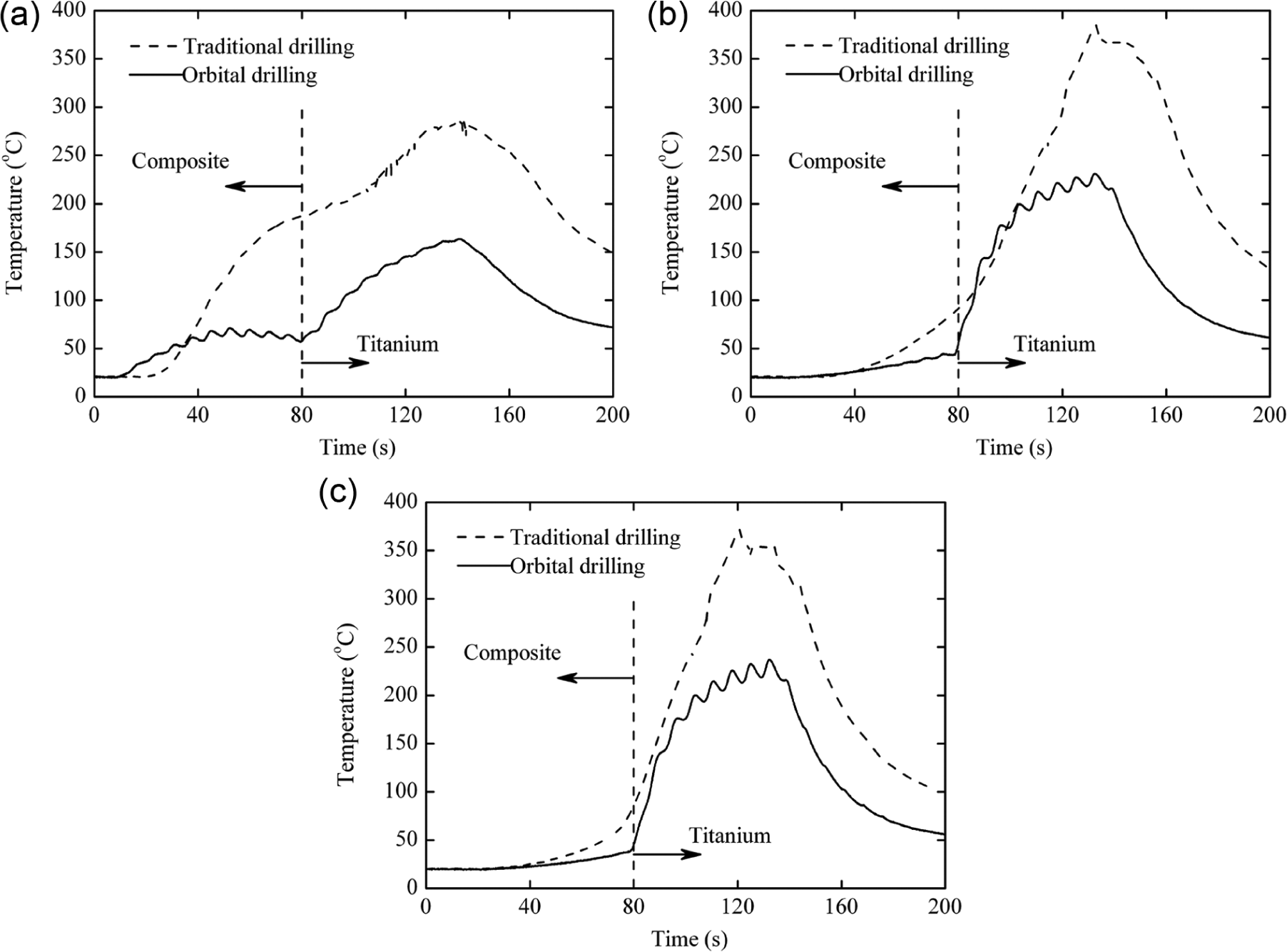
Variation of temperature during machining at (a) point A, (b) point B and (c) point C.
Maximum temperature during traditional drilling and orbital drilling (°C)
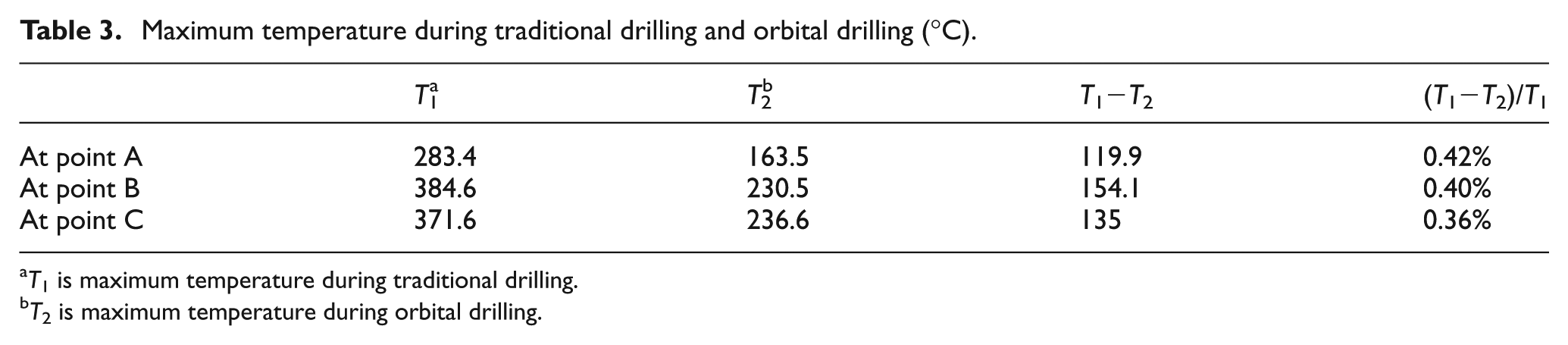
T1 is maximum temperature during traditional drilling.
T2 is maximum temperature during orbital drilling.
Titanium alloy or carbon/epoxy composite has a low thermal conductivity, which is much lower than most metals. Transverse thermal conductivities of titanium alloy and carbon/epoxy composite are about 7.31 and 1.04 W/m °C, respectively. 33
The cutting process of traditional drilling is continuous, and the cutting area is almost closed. Because the transverse thermal conductivity of the stack is much lower than that of metal tool, cutting heat is conducted outside mainly through the metal tool during traditional drilling. But cutting heat and cutting chips were difficult to be removed from the cutting area, even when there was a vacuum dust removal system (during traditional drilling, the cutting temperature generated was almost the same with or without the vacuum dust removal system). As a result, more friction heat was produced, which led to higher temperature. In contrast, orbital drilling is an interrupted cutting process, and the cutting area is semi-closed. During orbital drilling, vacuum dust removal system could directly take cutting heat and cutting chips away from the cutting area. Therefore, the heat transfer efficiency between the external environment and the cutting area was much higher. Compared with machining without vacuum, the cutting temperature generated decreased 14% using the vacuum dust removal system during orbital drilling.
Cutting force
Thrust force has a great effect on the generation of damages during drilling of composites, 34 and it has been considered as the main reason for delamination.35,36 During drilling of titanium alloy, cutting force has a significant effect on tool wear, but its influence on machining quality is not obvious.14,32 This article mainly focuses on the mechanism of machining damage generation, and tool wear during machining is not studied. Therefore, only cutting force in axial direction (Fz) is discussed.
The total ratio between milling and drilling (milling/drilling) in orbital drilling gives a constant value at every point of the helical course after the first cut. 24 It can be calculated as follows
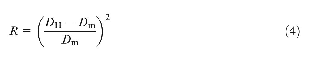
where R is the total ratio, DH is bore diameter and Dm is the diameter of the mill. In this experiment, the total ratio was 1/16. This indicates that the removal of material during orbital drilling is almost in the mode of drilling. As a result, the cutting force in axial direction during orbital drilling is generally as high as that during traditional drilling (as shown in Figure 4).
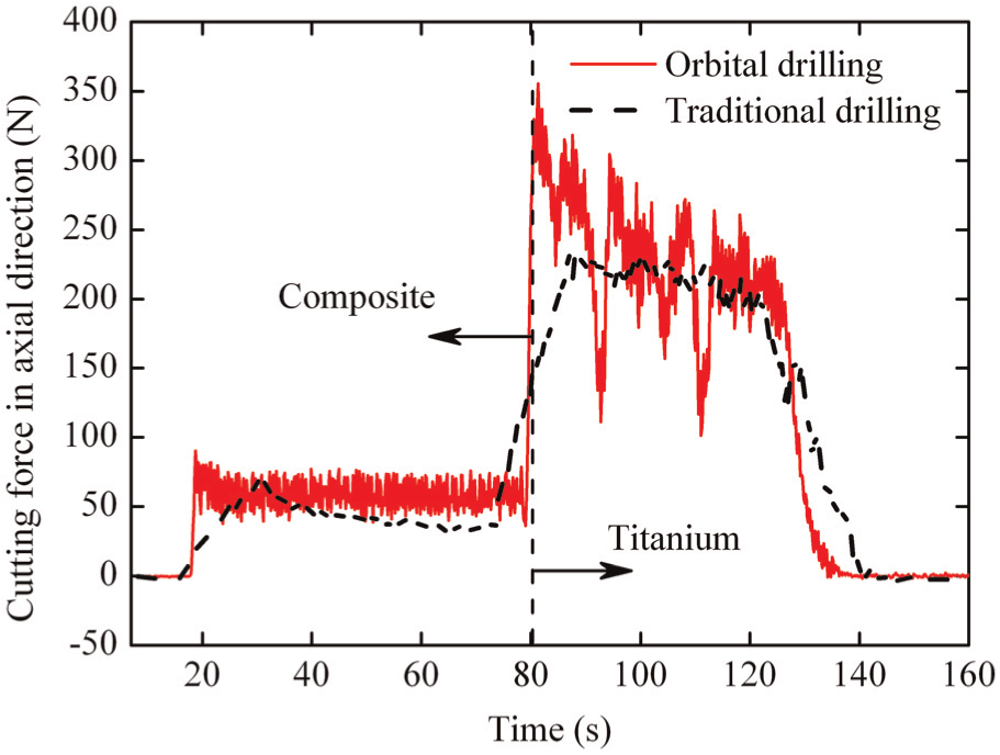
Variation of cutting force in axial direction.
Machining quality
During drilling of carbon/epoxy composites, damages are easily generated at exit. Main damages are delamination, spalling, fibre pull-out and so on. The machining quality at exit of composite material was detected. Figure 5 shows that the machining quality at exit after orbital drilling is much better than that after traditional drilling. Little damage was generated during orbital drilling, but a lot of spalling and fibre pull-out was generated during traditional drilling. The machining quality of hole wall generated by orbital drilling was much higher than that generated by traditional drilling (as shown in Figure 6). Serious damage, such as delamination and fibre pull-out, was generated during traditional drilling.
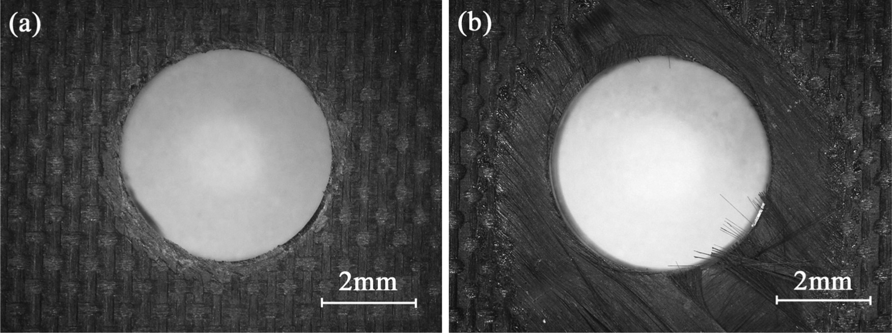
Machining quality at exit of carbon/epoxy composites: (a) orbital drilling and (b) traditional drilling.
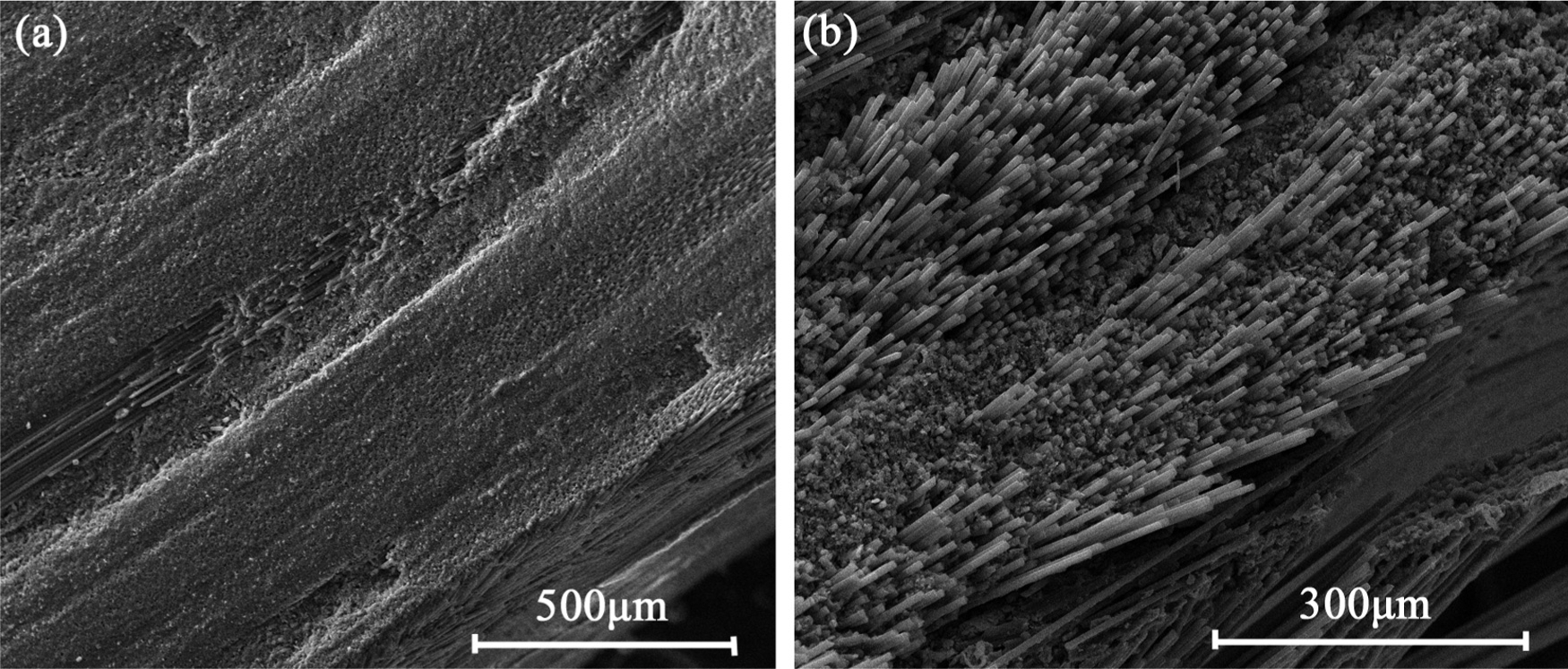
Machining quality of the hole wall of carbon/epoxy composites at exit: (a) orbital drilling and (b) traditional drilling.
Machining temperature and cutting force are the two factors, which determined the machining quality of carbon/epoxy composites.6,37 Thrust force is considered as a key factor for the generation of damage such as delamination, and larger thrust force induces more damages. It is believed that there is a critical thrust force below which no delamination appears. Based on linear elastic fracture mechanics, the simplest in its formulation and more used is the model presented by Ho-Cheng and Dharan. 38 In this model, the critical thrust force Fcrit at the onset of crack propagation can be calculated by the following equation
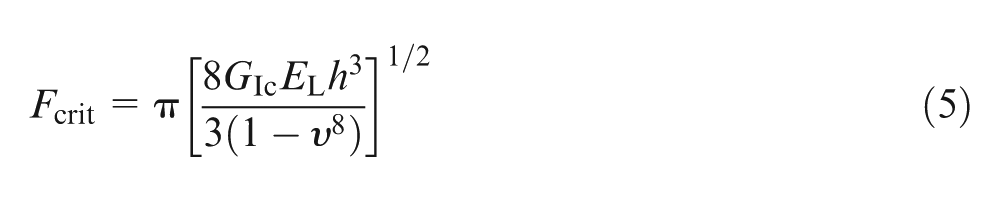
where GIc is the energy release rate in mode I, EL is the longitudinal elastic modulus of the unidirectional plate, h is the uncut thickness and v is the Poisson ratio of the material. To avoid the drilling-induced delamination, the thrust force should not exceed this value, which is a function of the material properties and the uncut thickness.
In a polymeric matrix composite, temperature has a great influence on the matrix dominant properties but has little effect on the fibre-dominant properties. Assuming that the longitudinal strains in fibres, matrix and composite are equal. The longitudinal modulus of a unidirectional fibre composite in one major direction can be written as equation (6) 39
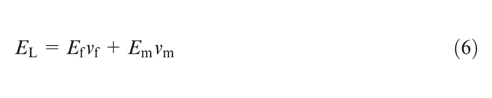
where vm is the matrix volume fraction, vf is the fibre volume fraction and EL, Ef and Em are moduli of the unidirectional composite, fibre and matrix, respectively. A composite can be considered as laminated by several unidirectional single-ply composites. The variation of temperature has almost no effect on the volume fraction (vf or vm) and modulus of the fibre (Ef). However, the modulus of epoxy resin (Em) will dramatically decrease if material temperature is higher than the glass transition temperature of the resin. 40
The glass transition temperature of the composite matrix (AG-80) is about 205 °C. 41 The cutting temperature results show that the temperature was about 205 °C during orbital drilling, while the temperature was much higher than 205 °C during traditional drilling. When the material temperature was higher than 205 °C, the decrease of resin modulus led to the decrease of the critical load Fcrit. Accordingly, although the thrust force was almost the same during traditional drilling and orbital drilling (as shown in Figure 4), serious damage was generated during traditional drilling. The decrease in the matrix properties also caused the decrease of the interlaminar strength as well as the fibre–epoxy interface strength. In turn, the low interlaminar strength and the low fibre–epoxy interface strength induced the generation of delamination, spalling and fibre pull-out near the exit (as shown in Figures 5 and 6).
Besides, a little epoxy resin appeared on the side wall after traditional drilling, as shown in Figure 7. This might be caused by the high cutting temperature. Because the cutting temperature at the interface was much higher than 205 °C, the decrease in epoxy resin modulus induced the cured epoxy resin to become viscoelastic. Under the pressure of the thrust force, the epoxy resin flowed to the interface.
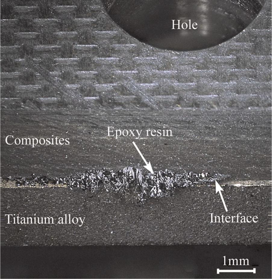
Epoxy resin on the side wall at the interface.
During drilling of titanium alloy, main damages are hole-wall roughness and burr height. Based on the detection of hole-wall roughness, it is found that the roughness of hole wall after orbital drilling is much lower than that after traditional drilling. As compared to traditional drilling, the hole-wall roughness reduced by at least 45% after orbital drilling. Furthermore, Figure 8 shows that orbital drilling produced higher machining quality than traditional drilling did during machining of titanium alloy.
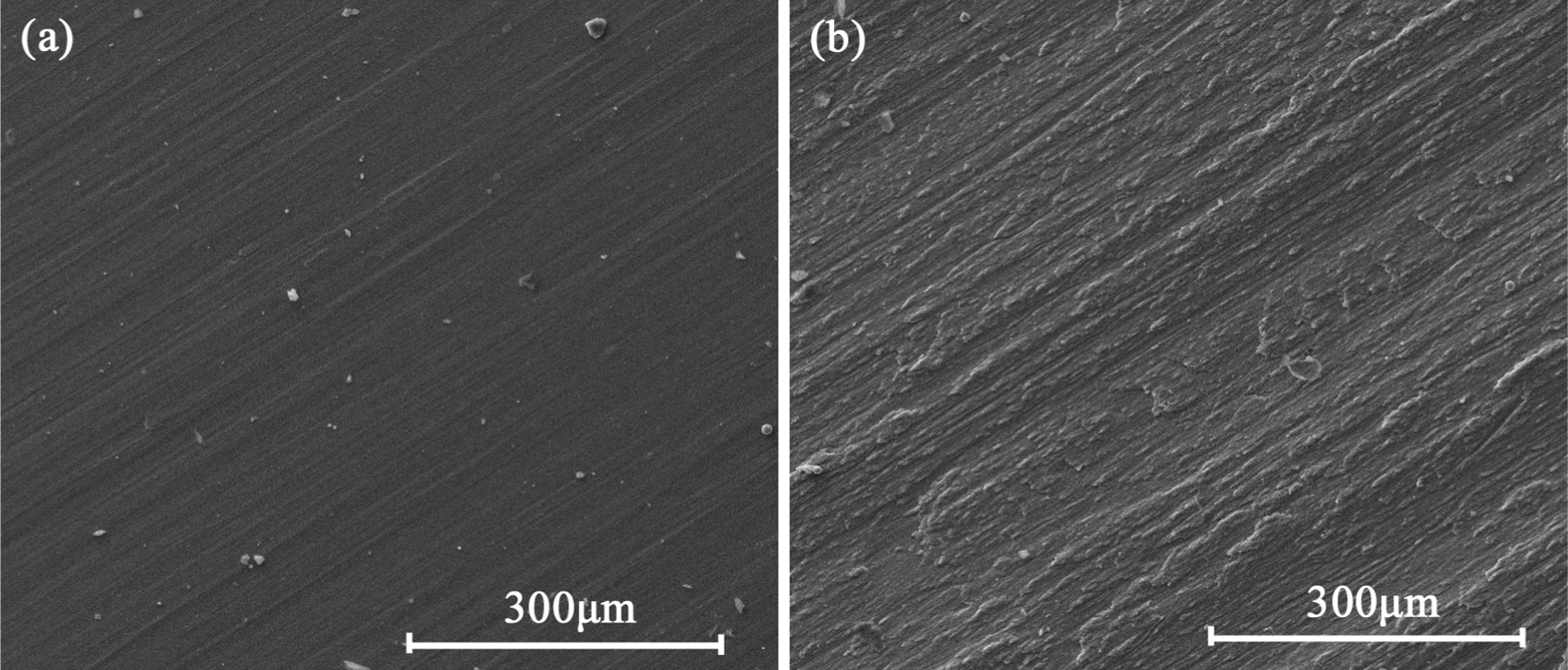
Machining quality of the hole wall of titanium alloy: (a) orbital drilling and (b) traditional drilling.
The continuous curling up of chips on the body of the tool is one of the most common problems encountered during drilling of multi-material. Chips should be broken into segments to ensure drilling and riveting in an automated assembly. Zitoune et al. 22 pointed out that the feedrate of cutting tool had a strong influence on the shape and size of chips generated during drilling of composites and metal stack. The shape and size of chips generated during orbital drilling and traditional drilling are shown in Figure 9. It can be found that machining process has a great effect on both the shape and size of chips. The high chemical reactivity of titanium at high temperature with most materials produces a strong adhesion of the workpiece or chip to the tool surface. 42 Due to the high temperature and continuous cutting chip generated during traditional drilling, titanium alloy easily adhered to the tool edge, as shown in Figure 10. As a result, the tool edges were not smooth any more, thus leading to the high roughness of hole wall.
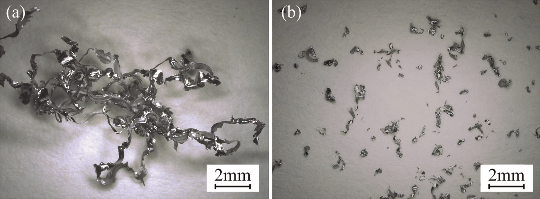
Influence of the machining process in the form of titanium chips: (a) traditional drilling and (b) orbital drilling.
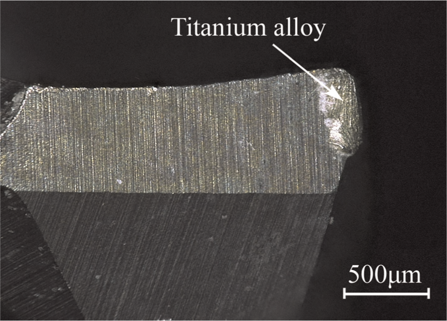
Titanium alloy adhered to the tool edge.
Denkena et al. 25 found that the bore hole diameter varied during orbital drilling, which was induced by the tool deflection. Therefore, both burr height of titanium alloy and variation in bore diameter were measured. The results showed that they were almost the same using two machining processes. The burr height was about 0.6 mm, and the variation of bore diameter was smaller than 0.055 mm.
Conclusion
In order to compare the machining quality of different cutting processes appropriately, both the cutting speed and the machining efficiency must be same. Therefore, the cutting parameters of the two machining processes should depend on each other.
Cutting heat generated during machining of titanium alloy conducts to the composites and leads to the increase of composite temperature. High cutting temperature induces the degradation of carbon/epoxy composite properties, which results in the generation of damage during machining of composites.
The cutting force in axial direction during orbital drilling is generally as high as that during traditional drilling. However, compared with the temperature during traditional drilling, the temperature during orbital drilling decreases more than 36.3%. The lower temperature during orbital drilling is responsible for the machining quality of orbital drilling being higher than that of traditional drilling.
Due to high cutting temperature and continuous cutting chip generated during traditional drilling, titanium alloy easily adheres to the tool edge, which causes the high roughness of hole wall. Both burr height of titanium alloy and variation of bore diameter are almost the same using two machining processes. The burr height is about 0.6 mm, and the variation of bore diameter is smaller than 0.055 mm.
Footnotes
Appendix 1
Declaration of conflicting interests
The authors declare that there is no conflict of interest.
Funding
This study was financially supported by the Important National Science & Technology Specific Projects of China (project no.: 2012ZX04003031), National Aerospace Science Foundation of China (Project No.: 20111663003) and National Natural Science Foundation of China (NSFC) (project no.: 50875034).