
Abstract
This article presents an integrated engine-hydro-mechanical transmission control algorithm for a tractor considering the engine-hydro-mechanical transmission efficiency. First, the hydro-mechanical transmission efficiency was obtained by network analysis based on the hydrostatic unit efficiency constructed from the test. Using the hydro-mechanical transmission efficiency map and the thermal efficiency of the engine, an engine-hydro-mechanical transmission optimal operating line was obtained, which provides higher total system efficiency. Based on the optimal operating line, an integrated engine-hydro-mechanical transmission control algorithm was proposed, which provides higher total powertrain system efficiency. To evaluate the performance of the proposed control algorithm, an AMESim-MATLAB/Simulink-based co-simulator was developed. From the simulation results for the plow working, it was found that the integrated engine-hydro-mechanical transmission control provides improved fuel economy by 7.5% compared with the existing engine optimal operating line control. The performance of the integrated engine-hydro-mechanical transmission control was also validated using the test bench.
Introduction
Manual transmission, power-shift transmission, hydrostatic transmission (HST), and hydro-mechanical transmission (HMT) are mainly used in tractors, with manual and power-shift transmissions the most common. These transmissions have the advantages of high efficiency and low cost, but need frequent gear shifts while the vehicle is being driven and while it is working, which requires a high degree of driving skills. Furthermore, an asynchronous manual transmission is inconvenient because the vehicle must be stopped before being shifted, which increases the working time and fuel consumption. Therefore, the need for automatic transmissions in tractors is growing with the demand for more efficient vehicles. 1
HST and HMT can continuously implement the desired gear ratios when driving or working because they have a continuously variable transmission (CVT) function. HST converts the engine power to fluid power through the hydrostatic unit (HSU), which acts as a variator, and then transmits the power to the drive shaft. HST offers the advantage of continuously variable speed changes through the HSU, but has the disadvantages of low efficiency, noise, heavy weight, and large size.2,3 HMT is a power split-type transmission (PST) that uses an HSU to transmit the engine power through the mechanical and hydraulic paths and can implement continuously variable speed change with the HSU. HMT has a higher power transmission efficiency than HST because it can transmit the power through the mechanical path, which is more efficient than the hydraulic path. Due to these characteristics, many tractor manufacturers are launching products using their own HMT models, including Vario from Fendt, S-Matic from Steyr, ECCOM from ZF, and Auto Power from John Deere.4,5
In conventional vehicles, fuel efficiency depends on the thermal efficiency of the engine. Thus, the gear ratio of vehicles is controlled in such a way that the vehicle will be driven on the optimal operating line (OOL), where the engine thermal efficiency is high.6,7 As for tractor and off-road vehicles, the engine speed control was also proposed using the engine OOL 8 and fuel economy operating curve 9 to improve fuel economy. In addition, to adapt the desired engine speed, polynomial fitting of a measurement data was used for tractor with HST. 10
However, as PST, including HMT, has a closed power path and a large loss depending on the speed ratio (SR), the efficiency of the total system, including the engine and the transmission, can be lowered only if the engine OOL is considered without the transmission efficiency. 11
In HMT, the power transmitted through the hydraulic path experiences greater loss than that of the mechanical path. Analytical studies were conducted on the power characteristics to increase the HMT efficiency by minimizing the power transmitted through the hydraulic path and maximizing the power through the mechanical path.3,12,13 Optimization techniques were also used to design efficient HMT.4,14 Considering the efficiency of the engine-PST, Kim et al. 11 proposed powertrain efficiency (PTE) control, which uses a dual-mode PST to control the gear ratio of hybrid electric vehicles (HEVs). However, the object of PTE control was limited to the electric CVT structure that uses an electric motor, and only the gear ratios of specific areas with higher efficiency were used, which could decrease the benefits of the continuously variable speed change feature.
In this study, an integrated engine-HMT control algorithm for improving tractor efficiency is proposed. For this purpose, HMT and tractor models were developed, and their power characteristics were analyzed. The HMT efficiency was analyzed through its power characteristics, and the engine efficiency was also considered for the proposed integrated engine-HMT control algorithm. The performance of the proposed integrated engine-HMT control algorithm was verified through simulations and a bench test.
HMT power characteristics
HMT configuration
Figure 1 shows a schematic diagram of the HMT system under study. The HMT consists of an HSU, a compound planetary gear set, and a sub-shift part. The HSU carries out the main gear shift function of the HMT and has a continuously variable speed change feature. The compound planetary gear set consists of PG1 (planetary gear 1) and PG2 (planetary gear 2). PG1 and PG2 separate the engine power into the HSU and the sub-shift part. The power-takeoff (PTO) shaft is connected to the engine shaft through the clutch. The operating power of the working device used for agricultural work is transmitted from the engine to the PTO shaft. The PTO clutch is disengaged when the working device is not required. The sub-shift part consists of four clutches for four-step gear ratios. CL1 (clutch 1) and CL3 (clutch 3) are on the same shaft and are connected to the carrier of the compound planetary gear set. CL2 (clutch 2) and CL4 (clutch 4) are on the same shaft and connected to the sun gear of the PG2. The sub-shift part is connected to the FOR (forward clutch) and the REV (reverse clutch). The FOR is used for forward motion, and the REV for reverse motion.
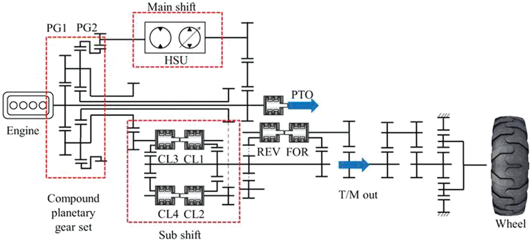
Schematic diagram of the target tractor.
HSU
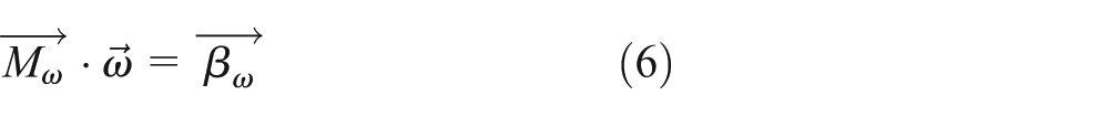
The HSU plays an integral role in the HMT. A variable displacement pump is used with a fixed displacement hydraulic motor. The torque and speed equation between the motor and pump in the HSU are represented as


where ω is the rotational speed, T is the torque, i stroke is the SR between the pump and the motor, sign(Tpump) is the direction of the power input to the HSU, ηvol is the volumetric efficiency, and ηmech is the mechanical efficiency. Although Wilson, McCandlish et al. presented mathematical models for the loss of the hydraulic pump and motor,15,16 the HSU efficiency was determined through an experiment in this study.
Figure 2 shows the efficiency measurement results of the HSU at ΔPHSU = 400 bar. The HSU efficiency changes with the input speed, the internal pressure difference of the HSU, and the i stroke. The ηvol is higher than 90% in most areas, but ηmech does not exceed 70%, and its efficiency change with i stroke is larger than those with ηvol.
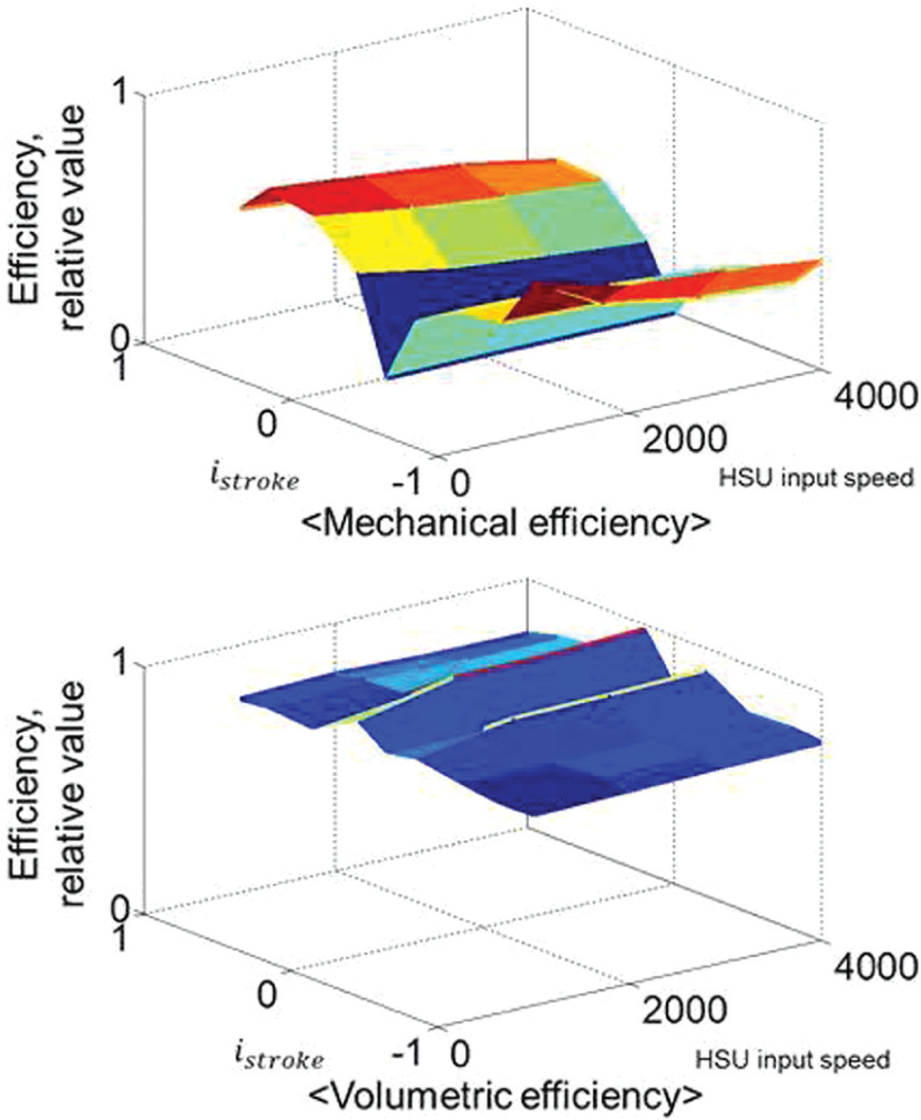
Mechanical and volumetric efficiencies of the HSU (ΔPHSU = 400 bar).
Compound planetary gear
The compound planetary gear connects the engine, the sub-shift part, and the HSU and distributes the engine power to the sub-shift part and the HSU. The output speed and torque of the compound planetary gear are input to the sub-shift part. When the sub-shift first or third gear is interconnected, the carrier is connected, and when the sub-shift second or fourth gear is interconnected, the second sun gear transmits power to the sub-shift part (Figures 1 and 3). The speed and torque in each case can be determined through lever analysis, as follows


Lever analysis of the compound planetary gear set.
where Z is the number of gear teeth; the subscripts S, C, R, and P represent the sun gear, carrier, ring gear, and pinion gear, respectively; and 1 and 2 refer to the first and second planetary gears, respectively.
Power characteristics analysis
The efficiency of the target HMT changes depending on the speed, torque (pressure), and i stroke, as described in section “HSU.” In addition, the direction and magnitude of the power flow are changed by i stroke. To investigate the power characteristic of the HMT in Figure 1, a network analysis was performed considering the aforementioned conditions. In the network analysis, the connection relations between the components of the transmission were configured as a network, and the transmission states of the speed, torque, and power of the total system were analyzed.3,11,17–19
Figure 4 shows the network model when the sub-shift first gear was engaged; i refers to the gear ratio between the shafts. The network model consists of the power transmission elements and shafts. Numbers 1–26 are the torque nodes, which are the same as the shaft nodes, and numbers ①–⑭ are the speed nodes. S3 and C3, between ⑬ and ⑭, denote the sun gear and carrier of the single-pinion planetary gear, which acts as the final reduction gear. When the sub-shift first gear is engaged, the second sun gear is not connected. In this case, it was assumed that the PTO shaft was not connected, and the forward clutch was engaged. The speed node ⑭ was the drive shaft of the tractor. The relationships between the torque and speed of each node can be expressed as follows3,20


Network model of the HMT for the sub-shift first gear.
where
Torque and speed equations for the sub-shift first gear.

To calculate the torque and speed, the HSU efficiencies, ηmech and ηvol, are required. However, since the ηmech and ηvol of the HSU change depending on the torque (pressure difference), speed, and i stroke, an iteration procedure is required.3,11,17–19
Figure 5 illustrates the HMT efficiency via the network analysis in each sub-shift gear according to the SR. SR is defined as the ratio of the wheel speed to the engine speed. In the network analysis, the efficiency of the mechanical elements was assumed to be 100% and only the HSU efficiencies were considered. It is seen in Figure 5 that the HMT efficiency is scattered at each SR because the efficiency of the HSU varies greatly according to the input speed and torque. When all the power is transmitted through the mechanical path, the HMT has 100% theoretical efficiency and this SR is called “mechanical point” (MP). 11 However, since the mechanical elements have the parasitic power loss such as clutch drag, bearing loss, gear transmission loss, and so on, 100% efficiency cannot be achieved in prototype HMT even at the MP. In the HMT under study, MPs appear at SR = 0.009 and SR = 0.022 for the first and third gears, respectively, and at SR = 0.023 and SR = 0.058 for the second and fourth gears, respectively. A comparison of the power characteristics of the first and third gears with those of the second and fourth gears shows that the second and fourth gears are more efficient and have a narrower width of change because the first and third gears transmit greater power through the hydraulic path.

HMT efficiency for the speed ratio.
Figure 6 illustrates the power ratio, or the power of the hydraulic path to the input power, according to the SR. The second and fourth gears transmit less power through the hydraulic path than the first and third gears. For this reason, the first and third gears are less efficient than the second and fourth gears (Figure 5). When the power ratio is 0, the power transmitted through the hydraulic path is 0, and all power is transmitted through the mechanical path, which becomes the MP. If the power ratio is negative, the input power flows in the reverse direction from the hydraulic motor to the hydraulic pump. This is called power circulation. Figures 5 and 6 show that HMT is less efficient when power circulation occurs; therefore, HMT must be operated in an area with high efficiency while the power circulation is minimized.

Hydraulic path power ratio for the speed ratio.
HMT control algorithm
The system under study can control the speeds of the engine and therefore a vehicle, using the CVT function of the HMT. To control the CVT system, various control strategies such as single-track, speed envelope, and off-the-beaten-track were investigated.20–23 In the single-track control strategy, the engine operation is implemented along the OOL, which is often used in automobiles. 21 This method maintains a high engine thermal efficiency by operating the engine along the OOL; but as the power characteristics analysis in section “HMT power characteristics” shows, the total system may become less efficient because the engine can be operated at points with low transmission efficiency. To address this problem, the PTE control was used, in which the power split-type HEV operates near the MP where the transmission efficiency is high. 11 However, the PTE control has the disadvantage of a narrower implementable speed range due to the limited CVT gear ratio. In this study, an integrated engine-HMT OOL is derived for the HMT-equipped tractor by considering the HMT efficiency according to the gear ratio, and the integrated control algorithm is presented.
Engine OOL
Figure 7 shows a map of the characteristics of the 70 kW engine used in the target system.

Engine characteristics map.
The OOL can be obtained by connecting the points with the minimum brake specific fuel consumption (BSFC) values on each iso-power curve. Therefore, efficient driving is possible if the engine can be operated on the OOL depending on the demanded power of the vehicle.6–9,11,24,25
The engine OOL control block diagram is shown in Figure 8. The demanded power is determined from the acceleration pedal (AP), which reflects the driver’s demand. Once the vehicle’s demanded power is determined, the demanded engine speed is determined through the engine OOL. The demanded engine torque is determined using the demanded power and the engine speed of the vehicle. To meet the demanded engine speed, the SR of the HMT must be determined. Before this is done, the sub-shift gear must be determined through the current HSU stroke, i stroke.
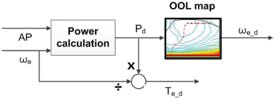
Engine OOL control block diagram.
Figure 9 illustrates the sub-shift gears according to the SR. The i stroke at the sub-shift first gear can be determined with the SR of the HMT as follows
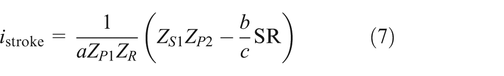
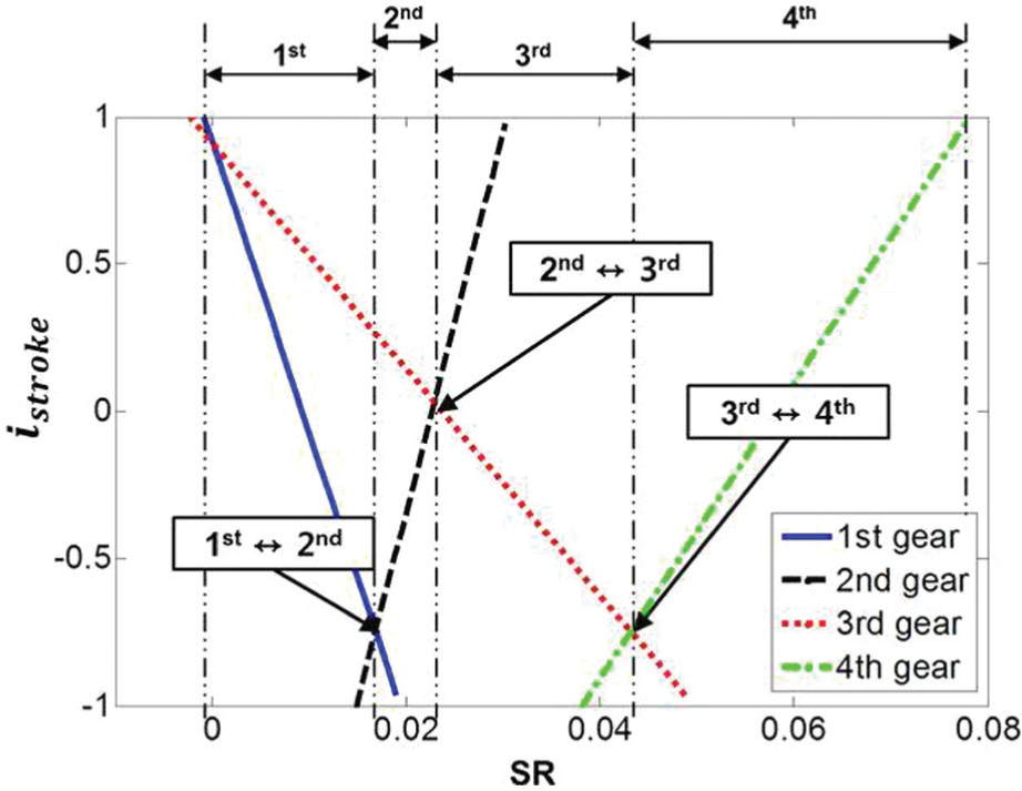
Sub-shift for the SR.
where a, b, and c are the constants that can be determined from the gear ratio at the sub-shift first gear. The relational expressions of the i stroke and the SR at the sub-shift second, third, and fourth gears can be determined in the same manner.
As shown in Figure 9, each sub-shift gear has a limited SR range according to the i stroke. The tractor under study begins at the HSU stroke i stroke = 0.87 at the sub-shift first gear and SR = 0. The shift of the sub-shift gears occurs at the point where the shifted gears have the same i stroke and SR. In other words, the first-to-second-gear up-shift and second-to-first-gear down-shift occurs when the first and second gear clutch speeds are identical at i stroke = –0.7194 and SR = 0.0171. The second-to-third and third-to-fourth gear shifts also occur at the intersections of the lines in Figure 9.
Once the sub-shift gear is determined, the HSU stroke, i stroke, that meets the demanded engine speed for the current vehicle speed can be determined.
Engine-HMT OOL
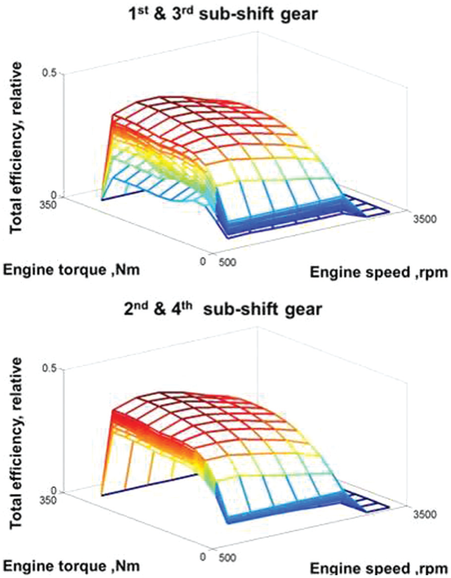
The network analysis results in Figure 5 show the changes in HMT efficiency according to the SR. The changes in the HMT efficiency for the input torque and speed are illustrated as three-dimensional graphs in Figure 10.

HMT efficiency for engine speed and torque.
The efficiencies of the first and third gears and the second and fourth gears are identical for the input torque, speed, and i stroke because if the mechanical path efficiency is assumed to be 100% and the i stroke values of the first and third gears and of the second and fourth gears are identical, the power transmission ratios of the hydraulic path are also identical (Figure 6). At i stroke = 0, when no power is transmitted through the hydraulic path, the transmission efficiency becomes 100% and appears as a flat plane (Figure 10).
To determine the efficiency of the engine-HMT system, the HMT efficiency and the engine efficiency in Figure 10 must be considered together. The engine efficiency at each operating point can be calculated from the engine BSFC contour in Figure 7 using the following equation 26

where for the fuel efficiency, the lower heating value of diesel (0.0119531 kWh/g) was used.
The engine-HMT system efficiency is determined by multiplying the HMT efficiency for each i stroke by the engine thermal efficiency determined using equation (8) (Figure 11).
Engine-HMT system efficiency.
In Figure 11, the engine-HMT system shows a high efficiency at high engine torques and low engine speed. The planes show the efficiency variations according to the i stroke. Being at the same i stroke value indicates the same plane in Figure 11, and the engine efficiency has a dominant effect on the efficiency of the engine-HMT system. However, at the same engine torque and speed, the efficiency is highest at the MP, i stroke = 0. Using the engine-HMT system efficiency in Figure 11, the required engine speed at which the total system efficiency is the highest can be determined for a given engine power and tractor speed.
In Figure 12, the integrated engine-HMT OOL is shown for the sub-shift first to fourth gears. Because the SR that can be implemented at each sub-shift gear is different, the available range of tractor speed also varies. The demanded engine speed ωe_d increases as the engine power increases, because ωe_d increases with the engine power on the engine OOL. In the case of the sub-shift first gear, ωe_d decreases near v tractor = 5 km/h following an increase because the efficiency of the total engine-HMT system is highest at the sub-shift first gear, at v tractor = 5 km/h. As the tractor speed subsequently increases, ωe_d decreases before increasing again. Similar trends were observed for the sub-shift second, third, and fourth gears.

Integrated engine-HMT OOL.
The integrated engine-HMT control block diagram is shown in Figure 13. For the given sub-shift gear and tractor speed, the demanded engine speed, ωe_d, is determined from the integrated engine-HMT OOL. The determination of the sub-shift gear and i stroke_desired to meet ωe_d is identical to the determination of the engine OOL control.
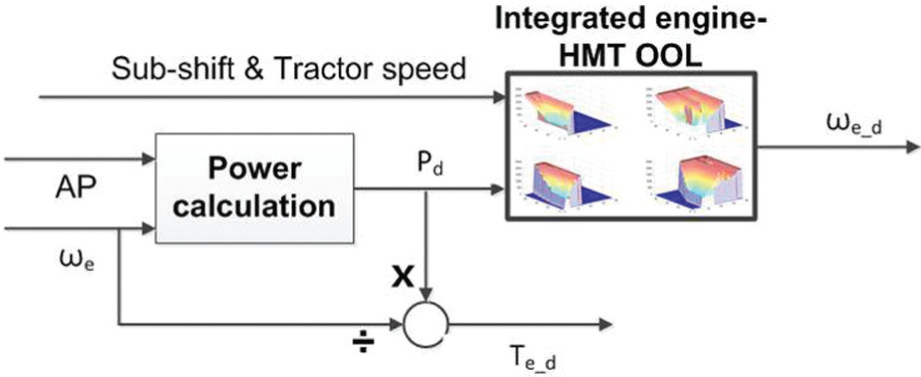
Integrated engine-HMT control block diagram.
Simulation results and discussion
Table 2 shows AMESim models of the HMT tractor. Using these models, a performance simulator was developed based on the AMESim software and MATLAB/Simulink to evaluate the performance of the integrated engine-HMT control (Figure 14).
AMESim models of the HMT tractor performance simulator.


Performance simulator of the HMT tractor.
Simulations were performed for the plow working, during which the PTO is not used. The load during plow working varies greatly depending on various parameters such as the soil condition, working depth, and working area.27–30 In this study, the loads measured during plow working were used. The load torque measurement of the plow working was conducted in Jeonju, the southwestern part of South Korea in May, Spring. To measure the plow working load, strain gauge type torque sensor was installed at the transmission input shaft, and the signal was transferred by radio telemetry (Figure 15). The load torque was measured at the tractor speed of v tractor = 10 km/h using a tractor equipped with a manual transmission, which was similar in size to the target tractor.
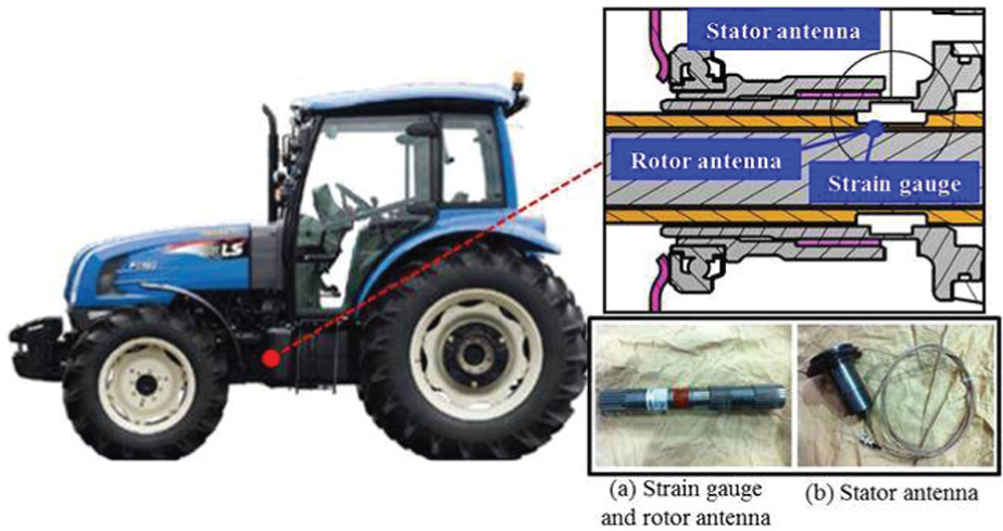
Torque measurement at tractor.
As shown in Figure 16, the tractor accelerates to 10 km/h at t = 0–10 s, maintains its working speed at t = 10–70 s, and decelerates from t = 70 s. During plow working at t = 10–70 s, the transmission input torque varies from 120–170 N m. The aforementioned data were converted to the load torque of the wheels in the simulations. The simulations were performed at the tractor speed of v tractor = 8 km/h and v tractor = 10 km/h during plow working. 31 In the simulations, the characteristics of the soil load were reflected in the wheel load torque during plow working by repeating the data for t = 10–70 s. The wheel load torque was assumed to be proportional to the tractor speed.

Transmission input torque during plow working.
Figure 17 shows the simulation results for the engine OOL control. The tractor speed (a) began to rise at t = 10 s and remained at 8 km/h during plow working. At t = 110 s, the speed decreased to v tractor = 2 km/h and then accelerated again to v tractor = 10 km/h for the plow working before decelerating at t = 250 s. The tractor speed followed the demanded speed. The wheel load (b) changed according to speed in proportion to the plow working load profile in Figure 16. After the engine was started, its speed (c) increased to 800 r/min, the engine idle speed, and sharply rose at t = 10 s when the tractor began to move. The tractor started with i stroke = 0.87, where the engine can operate at an idle speed. The demanded engine speed increased with the speed of the tractor. The tractor and engine speed fluctuated at t = 15–30 s, t = 110–120 s, t = 130–170 s, and t = 260–270 s when the sub-shift gear was shifted. The engine torque (d) showed a trend similar to that of the wheel load. The sub-shift gear (e) started in first gear and was shifted to second (P) and third (Q) gears as the SR (g) changed according to the HSU stroke (f). The sub-shift gear was maintained as the third gear during plow working. The HSU stroke showed a negative (–) value during plow working in order to ensure that the engine followed the OOL. The HSU stroke (f) was determined to follow the demanded engine speed as the tractor speed changed. It is seen that the engine (h) is operated near the engine OOL by the engine OOL control.
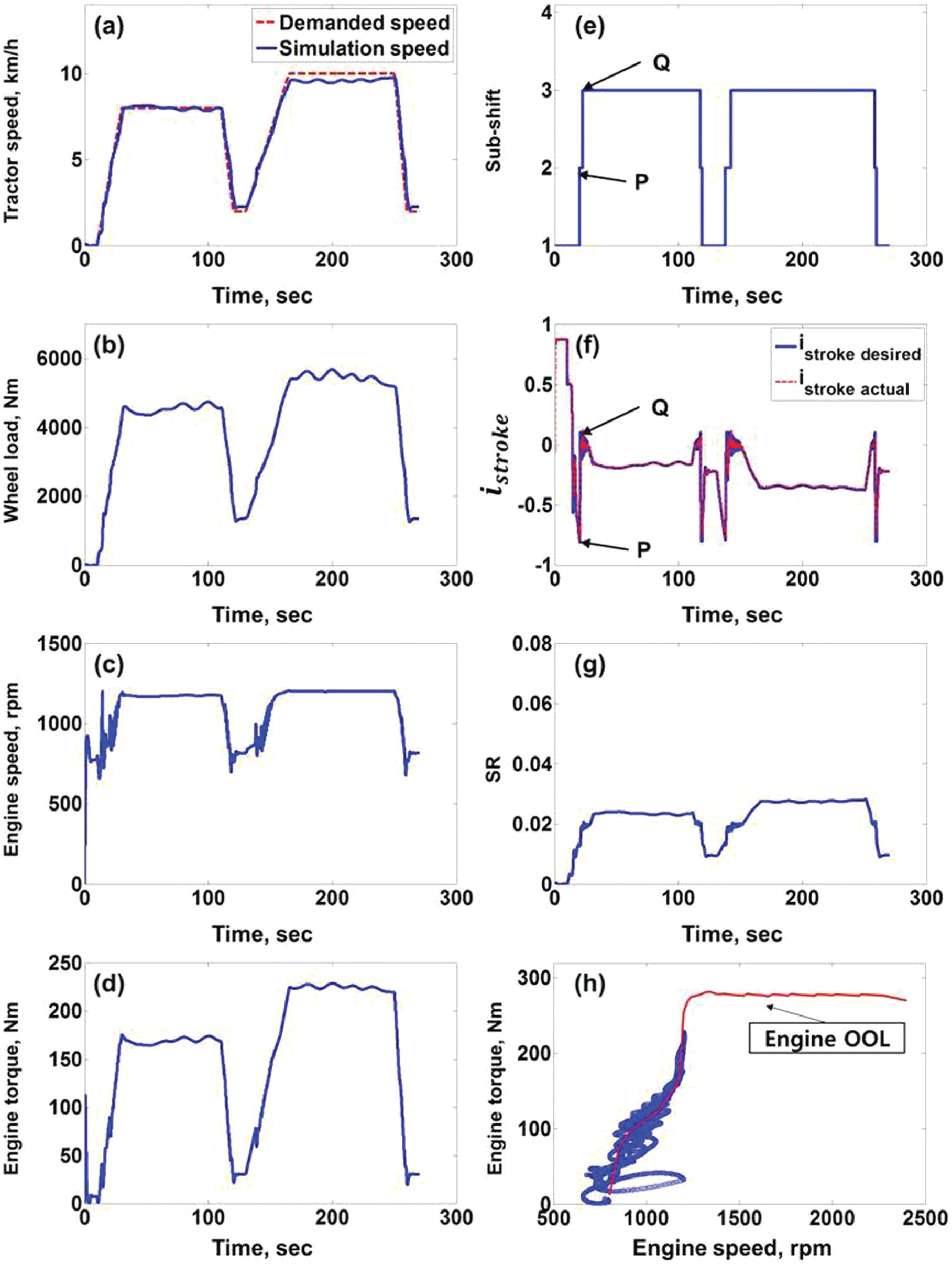
Simulation results for the engine OOL control.
Figure 18 shows the simulation results for the integrated engine-HMT control. The tractor speed (a) followed the demanded speed. The engine speed (c) rose sharply at t = 10 s (S) and then fell at 1420 r/min (T) before rising again. The engine speed change can be explained by the engine-HMT OOL. The engine-HMT OOL for the sub-shift first gear is shown in Figure 19. The engine speed increases from the point S to T as the demanded engine power increases and falls to P as the tractor speed increases. The sub-shift gear (e) was upshifted from first to second gear at point P. For the sub-shift second gear, the engine speed changed according to the engine-HMT OOL (Figure 12). The sub-shift gear was maintained as the second gear during plow working. The HSU stroke (f) was controlled at i stroke = 0 when the tractor speed was at a steady state during plow working because the efficiency of the engine-HMT system was higher at i stroke = 0, as shown in the engine-HMT OOL (Figure 12). As the tractor speed changed, the i stroke was changed to meet the demanded engine speed which had higher system efficiency; this was accomplished by raising or lowering the sub-shift gear. The SR (g) maintained a lower value during plow working than that of the engine OOL control because the engine speed demanded by the integrated engine-HMT control was higher than that of the engine OOL control. The engine (h) was observed to be operated out of the engine OOL; however, since the engine and the HMT were operated near the MP (i stroke = 0), the efficiency of the total engine-HMT system was improved by the integrated control.
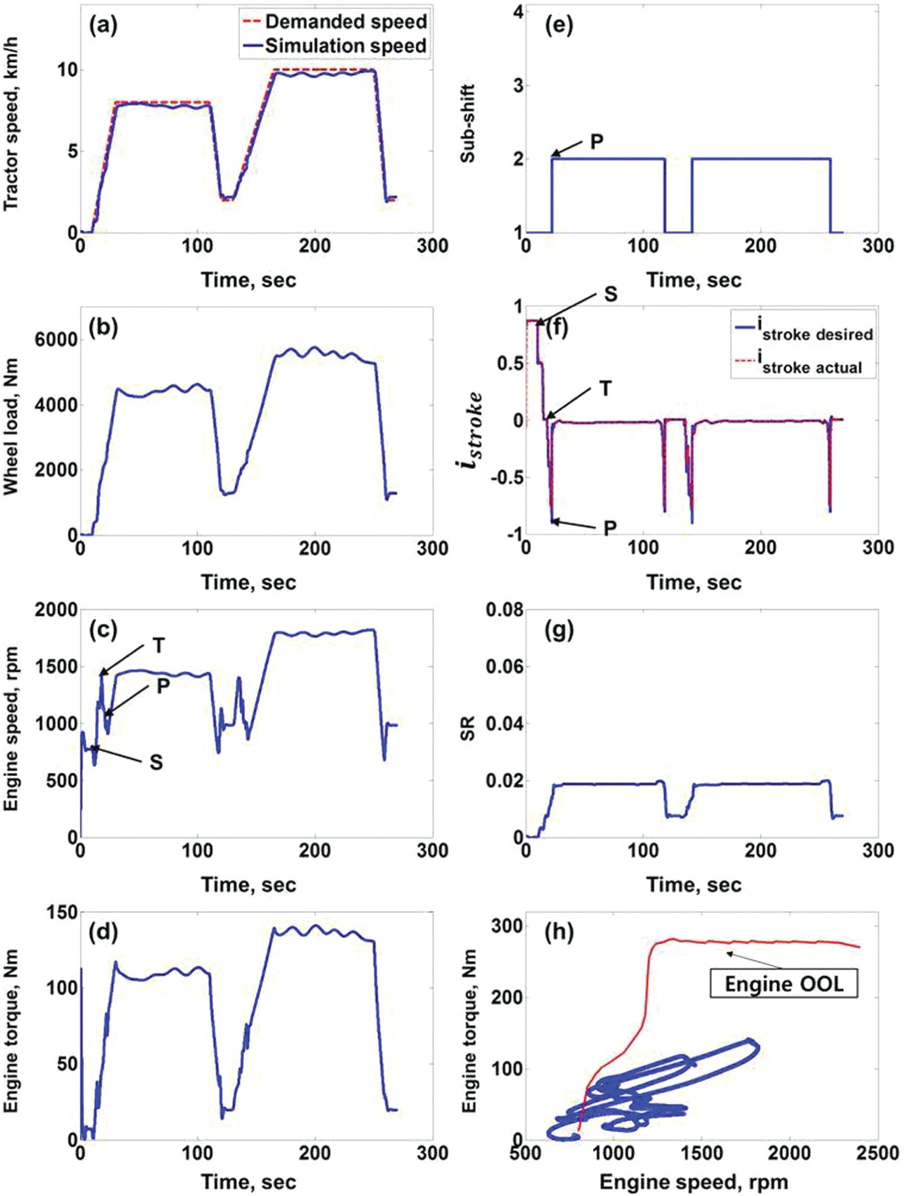
Simulation results for the integrated engine-HMT control.

Engine-HMT OOL on the sub-shift first gear (from Figure 12).
In Table 3, the efficiency of the engine OOL control was compared with that of the integrated engine-HMT control. The engine OOL control showed higher engine efficiency and lower HMT efficiency than the integrated engine-HMT control. The total efficiency of the integrated engine-HMT control was 2.1% higher than that of the engine OOL control.
Comparison of efficiency and fuel consumption of the simulation results.

OOL: optimal operating line; HMT: hydro-mechanical transmission.
The fuel consumption was calculated using the engine operation points and the BSFC map. To compare the fuel consumptions, the relative values of L/kWh and L/km were compared. As shown in Table 3, the fuel consumption of the integrated engine-HMT control was 7.5% (L/km) and 7.6% (L/kWh) lower than that of the engine OOL control.
In earlier works, besides the engine OOL control,8–10 gear up throttle down (GUTD) driving method had been used to improve fuel economy for tractor and off-road vehicles. 32 The GUTD driving is a fuel-saving practice that can be used when loads are lighter, since many field operations do not require rated power fully. For the lighter working, lower engine speed and higher gear guarantee higher engine efficiency. However, the GUTD has drawbacks such as engine-off when the field load changes abruptly. Compared to the GUTD, the integrated engine-HMT control proposed in this study can provide higher fuel economy independent of the engine load variation
Experiment
To evaluate the integrated engine-HMT control algorithm, a test bench was constructed (Figure 20), consisting of a traction motor, HMT, valve body, cooler, and dynamo motor. The 66 kW traction motor was used to simulate the engine. The HSU stroke and sub-shift control were performed through the valve body. Torque and speed sensors were mounted on the input and output shafts of the HMT. For the data acquisition, a MicroAutoBoxII by dSPACE was used to transmit signals and collect data. The load was applied with the dynamo motor.

Test bench of the HMT.
Using the test bench, the performance of the integrated engine-HMT control was investigated for plow working and compared with that of the engine OOL control. The plow working load was applied at the dynamo motor using the load profile in Figure 16.
Figure 21 shows the experimental results for the engine OOL control. The tractor speed (a) increased from 2 km/h, and plow working was performed at 8 km/h before decreasing again to 2 km/h. For the wheel load (b), the plow working load profile in Figure 16 was implemented in the dynamo motor according to tractor speed. The engine speed (c) increased from 800 to 1200 r/min as the demanded tractor speed increased and remained at 1200 r/min during plow working. The engine torque (d) showed a similar trend to that of the wheel load. The sub-shift gear (e) was upshifted from the first to the second (P) and third gears (Q) and was maintained in third gear during plow working. The HSU stroke (f) began at i stroke = –0.2 when the tractor speed was v tractor = 2 km/h. The magnitude and sign of the HSU stroke varied according to the tractor speed and sub-shift gear. When the tractor was accelerated, i stroke increased in the negative (–) direction. After the sub-shift gear changed from first to second gear, the i stroke increased again in the positive (+) direction. When the sub-shift gear was changed to third gear, the i stroke increased in the negative direction and maintained i stroke = –0.2 during plow working. The SR (g) increased with the tractor speed and showed a constant value of SR = 0.023 during plow working. The engine (h) was operated near the OOL by the OOL control.
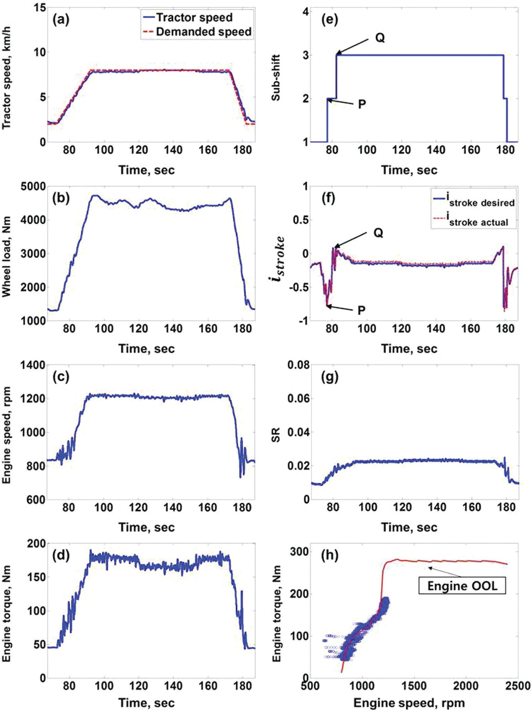
Experimental results for the engine OOL control.
Figure 22 shows the experimental results for the integrated engine-HMT control. When the tractor accelerated, the engine speed (c) began to rise (S) and fell before it increased again to 1300 r/min, at which point the plow working began. As shown in the simulation result (Figure 18), as the tractor speed increased in the sub-shift first gear, the demanded engine speed changed to follow the engine-HMT OOL. When the engine speed reached 1300 r/min (T), it began to decrease to follow the engine-HMT OOL. After the HMT shifted from the first to the second gear (P), the demanded engine speed decreased further as the SR (g) increased, and then rose again to satisfy the engine-HMT OOL. The demanded engine speed showed a similar response to that of the simulation results (Figure 19). The sub-shift gear (e) started at the first gear and upshifted to the second gear at point P. The second gear was maintained during the plow working. Unlike the simulation results (Figure 18), the HSU stroke (f) started at the MP (i stroke = 0) because the experiments were performed at v tractor = 2 km/h. At the sub-shift first gear, the HSU stroke increased in the negative direction to operate the engine on the engine-HMT OOL. When the sub-shift gear shifted to the second gear at the point P, the HSU stroke was controlled at i stroke = 0 (MP). The SR remained at SR = 0.02, which is lower than the engine OOL control because the engine speed was maintained higher than the engine OOL control for the same tractor speed. The engine operation (h) was performed out of the engine OOL because the engine was controlled to follow the engine-HMT OOL by the integrated engine-HMT control.

Experiment results for the integrated engine-HMT control.
In Table 4, the efficiency and fuel consumption of the test results were compared. The engine OOL control showed higher engine efficiency and lower HMT efficiency than the integrated engine-HMT control. The total efficiency of the integrated engine-HMT control was 0.8% higher than that of the engine OOL control. The efficiency of the HMT was 59.5%, which is lower than the simulation result of 76.7% (Table 3). This is because the HMT used for the bench test was a working sample in the development stage, and the efficiency of the HMT’s mechanical path was low due to friction loss of the compound planetary and reduction gears.
Comparison of efficiency and fuel consumption of the bench test results.
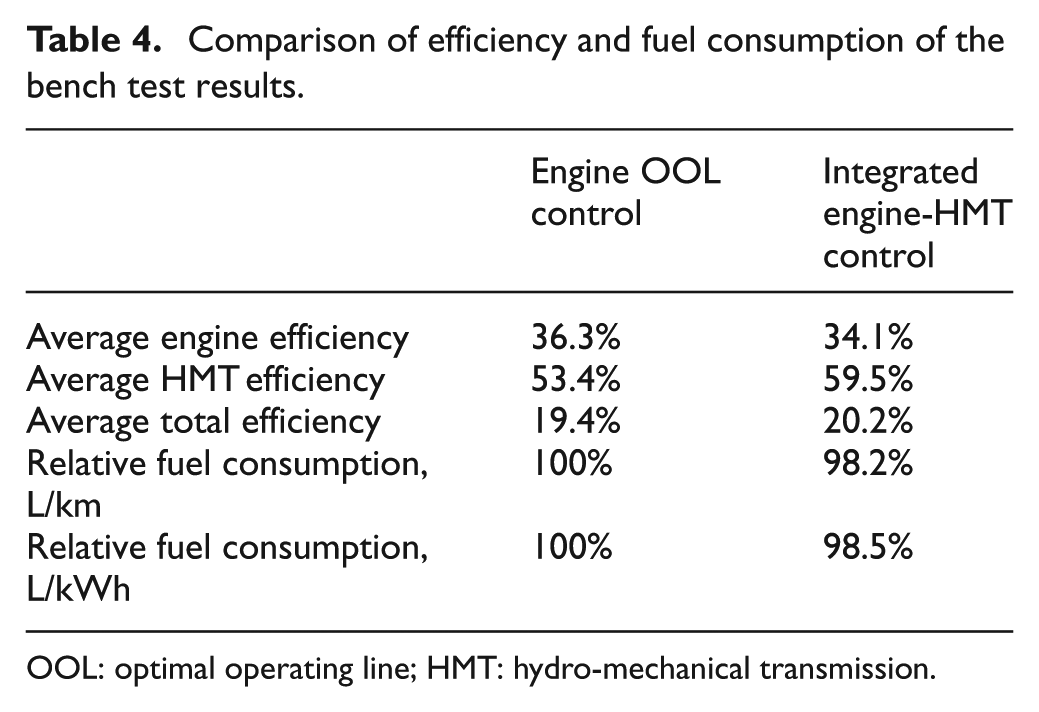
OOL: optimal operating line; HMT: hydro-mechanical transmission.
As shown in Table 4, the fuel consumption of the integrated engine-HMT control is 1.8% (L/km) and 1.5% (L/kWh) lower than that of the engine OOL control. The reduction in fuel consumption is lower than the simulation result because the efficiency of the working-sample HMT used for the bench test was even lower in the mechanical path. It is expected that the efficiency could be improved by enhancing the efficiency of the mechanical components, such as replacing the spur gears of the compound planetary and reduction gears with helical gears during the HMT prototype development.
Conclusion
An integrated engine-HMT control algorithm was proposed for a tractor. The HMT investigated in this study consisted of an HSU and a compound planetary gear. The HSU featured a CVT, and the compound planetary gear provided four sub-shift gear ratios. A network analysis was performed to obtain the HMT efficiency with regard to the HSU stroke and the sub-shift gear ratio. In the network analysis, the HSU efficiency map constructed from the test was used. Using the HMT efficiency map and the engine thermal efficiency, an engine-HMT OOL was suggested. Based on the OOL, an integrated engine-HMT control algorithm was proposed, which provides higher total system efficiency for the demanded engine power, tractor speed, and sub-shift gear ratio. To evaluate the performance of the proposed control algorithm, an AMESim and MATLAB/Simulink-based co-simulator was developed, and the performance simulations were performed for the plow working. In the simulation, the load torque of the plow working was applied, which was obtained from the field test. The simulation results show that the integrated engine-HMT control improves fuel economy by 7.5% higher than the existing engine OOL control, since the proposed control algorithm improved the engine-HMT’s total system efficiency even when the engine was operated outside of the engine OOL. The performance of the integrated engine-HMT control was validated using the test bench. It was also found that the fuel consumption of the integrated control can be reduced compared with that of the conventional engine OOL control.
Footnotes
Academic Editor: Rahmi Guclu
Declaration of conflicting interests
The authors declare that there is no conflict of interest.
Funding
This research was supported by the Advanced Production Technology Development Program of the Ministry of Agricultural, Food, and Rural Affairs of Republic of Korea.