
Abstract
With the development of metallurgical industry and the improvement of kiln technology, the processing properties of kiln equipment are being paid more attention. The rotary kiln is one of the most representatives of the furnace equipment; higher requirements of the rotary kiln are put forward in response to the call of the national energy saving and emission reduction. That is, the new designed equipment has the characteristics of the optimal energy consumption and stable performance. In order to analyze the energy consumption of the rotary kiln, it is necessary to study the heat transfer process of the rotary kilns. The three-dimensional numerical model of the rotary kiln is set up by using the finite element technology. After analyzing the data, it is found that different thicknesses of the kiln crust and different working conditions have certain influence on the rotary kiln’s temperature field and stress field. After analyzing the result of the simulation, the temperature of the rotary kiln’s outer wall has an approximate linear relationship with the thickness of the kiln crust. Changing the thickness of the kiln crust will not only alter the value of the maximum stress but also have influence on the position of maximum stress. The increase in the thickness of the kiln crust can reduce the extreme value of stress. When the wind speed of induce fan inside the kiln is larger, the temperature of each layer will be relatively high as well, and the temperature curve is softer, and the temperature variation is more stable. It has also been found that when the comprehensive coefficient of heat exchange outside the kiln surface is larger, the thermal stress created by the body of kiln is smaller. The phenomenon of excessive thermal stress can be improved by changing the outer surface ventilation conditions of the rotary kiln. In order to ensure that the high temperature of the kiln wall has no influence on working wheels, and make sure the temperature of the kiln wall is well-distributed along the length direction of the kiln, the thickness of the kiln crust along the length direction is changed, and the structure of the cylinder with wheels on it is altered. After further numerical simulation, the optimized thickness of the kiln crust and kiln structure is found, and the above problem is solved effectively. The results can reduce the inputs of rotary kiln design and the production costs. It can also reduce energy consumption, and some guidance is given on the production process of kilns.
Introduction
With the development of metallurgical industry, boilers are more and more widely used. Since calcining in boilers has become an indispensable part of industrial production processes, boiler burning technology is increasingly becoming mature. The rotary kilns are most commonly used in boilers, which are widely used in calcining solid materials. 1 Due to the development of metallurgical technology, the update frequency of metallurgical equipment is also very high. Only if the structure of the rotary kiln is constantly improved, it can meet the needs of new technology. The working environment of the rotary kiln is relatively bad. The rotary kilns always run in the condition of high temperature, and thus, the rotary kilns should be equipped with the ability to adapt to the bad working conditions. In order to make rotary kiln work more stable and have a longer life and higher production efficiency, it is necessary to analyze its temperature field and stress field under different structure and working conditions.
The beginning of rotary kiln research in China is relatively late, the study of heat conduction is also fairly little, and the relevant literature and books that can be referred to are few. Qiu and Han 2 assumed that the material and the kiln wall were all gray body; its temperature distribution was relatively uniform in the region, which was divided into a number of smaller ones along axis; and they also assumed that there was no heat transfer between the material and the covering walls. Then, they set up a one-dimensional (1D) mathematical model of the rotary kiln by using the heat emission coefficient method theories. This method not only needs little calculation but is relatively simple, which can be regarded as the theory foundation of kiln thermal simulation and optimal control. Ma and Zhou 3 took the alumina calcining the rotary kiln as a sample to conduct further analysis and research on its internal heat transfer and considered the conduction and radiation of heat between high-temperature flue gas, kiln wall, and the bed of material. On this condition, they established 1D heat transfer model of alumina calcination rotary kiln. This kind of 1D model of the rotary kiln can forecast the temperature of the area which is enclosed by gases and materials and optimize the parameter. This method is very effective in the absence of experimental conditions. Zhang et al. 4 also analyzed the heat transfer process of the rotary kiln. On the basis of previous research, they focused on the mechanism of heat transfer between material bed and covering walls and the effect that rotation has on the coefficients of heat transfer. The beginning of industries in the developed countries is earlier, the research is also relatively mature, and many foreign scholars already started to study on the mathematical model of heat transfer process of the rotary kiln and have got many achievements. Their researches are deeper and more meticulous than us. Patisson et al. 5 took the coal pyrolysis kiln as the object for study, and then they set up the heat transfer model for coal pyrolysis on the basis of a lot of analysis and description. They predicted the temperature distribution along the axis and the composition of gas and material inside the rotary kiln by numerical simulation method. After completing this model, in order to verify the validity and applicability of the model, Martins et al. 6 also did some research on internal heat transfer process of the rotary kiln. They focused on the kinetics properties and flow characteristics of mass transfer process between gas phase and mass phase, as well as the impact they had on internal heat transfer process of the rotary kilns. On the basis of this research, they set up 1D heat transfer mathematical model of the calcination process of the rotary kiln. This model took full account of the effect of mass transfer process on the heat transfer process in the kiln, so that the model can have some practical values. It also provided a new basis for further research. Boateng and Barr 7 also had done a lot of effective work on internal heat transfer process of the rotary kiln. They mainly studied the movement of particles inside the calcined material, and the most important achievement they made is the establishment of quasi three-dimensional (3D) model of the internal heat transfer in the rotary kiln. Since this model did not directly reflect the temperature distribution of material bed in 3D spaces, it is called quasi 3D heat transfer model. Although their study had some limitations, they provided an effective concept for setting up the 3D model of the internal heat transfer in the rotary kiln and laid the foundation for subsequent studies. Bui et al. 8 built the 3D model of petrol coke rotary kiln on the basis of previous research, and the gas phase model was added into the model, which made the model more perfect. The whole model included several complex physical phenomena, namely, the relative motion of air and material, the heat transfer between the materials, the volatile of components, combustion, particle movement, and the thermal effect of the side walls.
The remainder of this article is organized as follows. Section “Establishment of 3D finite element model of rotary kiln” presents the establishment of the 3D finite element model of the rotary kiln. Section “Influence factors of temperature field and stress field of the rotary kiln” discusses the influence factors of temperature field and stress field of the rotary kiln. Section “Optimization analysis of rotary kiln structure” overviews the optimization analysis of rotary kiln structure. The last section concludes this article.
Establishment of 3D finite element model of rotary kiln
The process of rotary kiln analysis using finite element software is shown in Figure 1. After the 3D geometry model is built, it can be imported into the analysis module to establish the finite element model. The finite element model mainly comprises the geometric model of parts in a kiln body, the definition of material parameters, and the finite element mesh generation.

Rotary kiln finite element analysis flow chart.
Establishment of the 3D model of the rotary kiln is mainly to define each component’s structure and material properties. Without affecting the study results, some adjustments will be made to the established structure, material property model, and practical rotary kiln for simulation calculation. Combined with the specific structure in practical rotary kiln, the following several factors of the modeling are determined: 9
1. The choice of the kiln body form
The commonly used industrial production of rotary kiln body is mainly in the form of straight barrel type, enlargement type at the hot side, enlargement type at the cold side, and dumbbell-shaped type; they all have their own characteristics.
Straight barrel type has the same diameter throughout the kiln. It has simple structure and it is easy to manufacture and maintain.
Enlargement type at the hot side expands the combustion area, namely, combustion zone diameter, and increases the volume of the arid zone, so the heating capacity of the rotary kiln is improved. While the flame radiation layer’s thickness is increased, the heat transfer effect of the high-temperature region can also be improved availably.
Enlargement type at the cold side expands the diameter of preheating zone and arid zone, improves preheating the ability of kiln, and reduces the temperature of exhaust gas in kiln tail effectively.
Dumbbell-shaped type increases the diameters of all the cold side and hot side. The increase in diameter at the cold side is to keep the gas flow rate stable with changing pressure when the heat exchange device is installed. The increase in diameter at the hot side is to improve the heating capacity of the kiln and middle contraction can save steel consumption. The straight barrel type of kiln body form is chosen to study in order to facilitate the simulation and analysis.
2. Shell material
Steel cylinder is welded with 50-mm steel plate. Along the length direction, every certain distance is provided with a supporting wheel. The rotary kiln is installed with four wheels. Cylinder’s body is supported on the roller through the four wheels.
3. Interior material
The kiln interior material includes two parts, namely, the refractory brick and kiln crust.
Because the working environment of the different calcination sections in rotary kiln axial direction is different, the materials should be chosen in terms of the different working requirements. The head part of kiln with serious erosions should use the material with high-temperature resistance and good thermal shock stability. Calcination zone is under high-temperature impact and chemical erosion. The material should be high-temperature resistant and it should be an easily sticking material at high temperature. The exothermic reaction zone works at unstable and high temperature, so it should be selected to withstand high-temperature impact, flexural strength, and smaller elastic modulus. The decomposition zone and pre-tropical adjacent region have small thermal stress, so ordinary clay brick and high alumina brick can be used. The decomposition zone and exothermic reaction zone adjacent region have high temperature and mechanical wear, so high alumina brick or common magnesia chrome brick can be chosen. Pre-tropical zone uses clay tiles. Discharging hatch and cooling zone has mechanical wear and chemical erosion, so the material with thermal shock stability and abrasion resistance should be chosen.
Segment modeling is taken into account according to the above description, but using of different materials has brought certain difficulty of modeling. In order to facilitate the modeling and calculation, good comprehension performance of the material is chosen. So, this treatment will not have a great impact on the research effect.
Combined with the specific structure of practical rotary kiln and the above analysis, 3D model of a rotary kiln using the modeling software Design Modeller ANSYS Workbench is shown in Figure 2. The numerical model is established with the cylinder, firebrick, kiln crust, and wheel. The rotary kiln is provided with a certain gradient in the modeling process. The rotary kiln in this simulation has the inclination of 0.04. The thickness of each part is as follows: kiln crust is 200 mm, firebrick is 150 mm, cylinder is 50 mm, and wheel is 300 mm; the width of the wheel is 500 mm.

Three-dimensional model of rotary kiln.
The material’s physical parameters have an important influence on heat transfer, stress, and strain of the kiln body. In the modeling of the rotary kiln, it is focused on the structure of firebrick, cylinder, and wheel and kiln crust. The related physical parameters are the material density, specific heat, coefficient of thermal conductivity, modulus of elasticity, Poisson’s ratio, coefficient of thermal expansion, and so on. According to the above discussion, the required material physical parameters in this study are shown in Table 1.
Physical parameters of related materials in the simulation.

The situation of furnace heat transfer is more complex, heat convection of hot airflow on rotary kiln lining is mainly considered, and radiative transfer of flame on kiln lining is converted into convective coefficient of heat transfer, ignoring heat conduction and thermal radiation of the materials on kiln lining. The kiln temperature distribution curve along the furnace airflow length direction can be used as boundary condition of airflow temperature in rotary kiln lining. 10
The outside surface of rotary kiln cylinder transfers heat to the outside air in the form of heat convection and heat radiation. Under different temperatures and wind speeds, the integrated coefficient of heat transfer on the outside surface of the cylinder is not the same. The environment of job shop in practice is more complex, and therefore, the temperature and wind speed data are hard to measure. In general, convection coefficient of heat transfer between the outside of the rotary kiln and air is 5–10 W/m2 K; a more accurate calculation equation is shown as follows

where
The radiation heat transfer between the outside of the rotary kiln and the surrounding environment is transferred into the equivalent convective heat transfer coefficient

where
It could be negligible when the surface area of the rotary kiln is compared with propagation distance, radiation source can be thought of as “a point heat source” and its radiation is similar to the radiation heat transfer coefficient of the two planes F1/F2 which is close to 0, so the radiation coefficient is assigned as 0.8. The Boltzmann constant

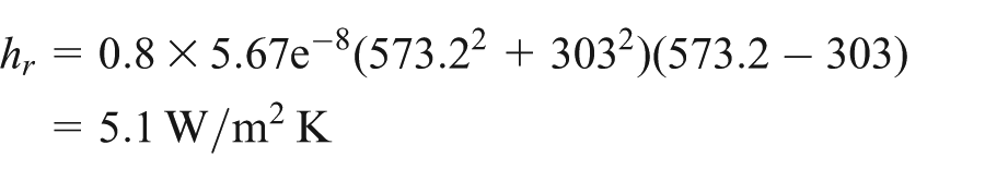
Convective coefficient of heat transfer is
Influence factors of temperature field and stress field of the rotary kiln
Influence of the kiln crust thickness on the temperature of kiln’s outer wall
Under the condition that kiln body material and wind speed of kiln’s outside surface are constant, the temperature of the rotary kiln’s outer wall is mainly affected by kiln crust thickness and the temperature of the rotary kiln’s inner wall.
Because the rotary kiln is an axisymmetric structure, any part of the inscribed angle of the rotary kiln can be taken for analysis. In order to facilitate the calculation, the 3D model of the rotary kiln at 30° angle is established. It is shown in Figure 3.

Three-dimensional mode of a rotary kiln at 30° angle.
A total of 11 3D modes similar to Figure 3 are built, whose kiln crust thickness is from 100 to 300 mm with tolerance of 20 mm. 11 Then 31 different temperatures from 500 °C to 2000 °C with tolerance of 50 °C for the rotary kiln’s inner wall are set for each model. Through analyzing and calculating the 11 above models one by one from the diagram shown in Figure 4 (listed 120, 140, and 160 mm), 341 temperature date of the rotary kiln’s outer wall can be concluded as in Table 2.
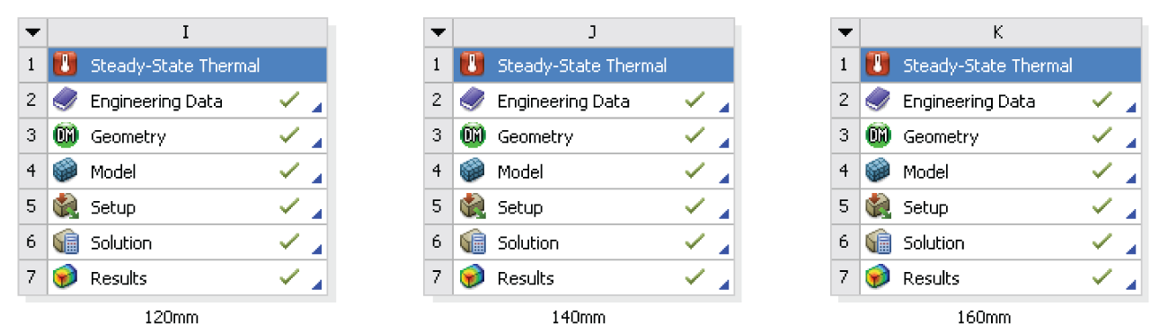
Calculation block diagram of the experimental model.
The temperature of kiln’s outer wall with different kiln crust thicknesses and temperatures of kiln’s inner wall.

H represents the kiln crust thickness (unit: mm); T represents the temperature of rotary kiln’s inner wall (unit: °C).
In order to know the influence of the kiln crust thickness more intuitively, the temperature of the kiln’s outer wall from Table 2 can be imported into MATLAB software to fitting 3D surface plot about temperature change in the rotary kiln’s outer wall with different kiln crust thicknesses and temperatures of the kiln’s inner wall. See Figure 5.

Three-dimensional surface plot about temperature change in rotary kiln’s outer wall with different kiln crust thicknesses and temperatures of kiln’s inner wall.
As can be seen from Figure 5, the 3D surface plot about temperature change in the rotary kiln’s outer wall with different kiln crust thicknesses and temperatures of the kiln’s inner wall is approximately a plane, which indicated that the temperature of the kiln’s outer wall and kiln crust thickness is approximately in linear relationship. Furthermore, the state of kiln crust can be determined through the temperature of the rotary kiln’s outer wall. It can offer valuable reference for maintenance management of the kiln crust in rotary kiln production.
Influence of kiln crust thickness on stress field
The changes in kiln crust thickness have double effect on stress field. First, it can affect the temperature distribution of the rotary kiln body, and then it can also change the structure strength of the rotary kiln. The influence of kiln crust thickness on stress field can be detected by comparing the stress distribution in different kiln crust thicknesses.
Two rotary kiln models with different kiln crust thicknesses are built. Simulated stress nephograms are shown in Figures 6 and 7, respectively. The kiln crust thickness is equal in Figure 6; it is 200 mm. The kiln crust with piecewise thickness is used in Figure 7.

Stress nephogram of kiln crust with uniformity thickness.

Stress nephogram of kiln crust with piecewise thickness.
It can be seen from the stress nephogram that stress is concentrated in the place where the cylinder contacts with the wheel; the changes in kiln crust thickness will not only change the magnitude of maximum stress but also change the position of the maximum stress; and the increase in kiln crust thickness can reduce the extreme value of the maximum stress.
Influence of the wind speed inside the kiln on rotary kiln temperature field and stress field
The different wind speeds inside the rotary kiln can affect the velocity of airflow in the rotary kiln, which has a great influence on the heat transfer between the material and the inner wall. The size of the wind speed directly affects the air ambient temperature of the kiln’s inner wall, so that the temperature field and stress field of kiln will also be changed accordingly. The simulated internal air temperature curves as a boundary condition are applied to the kiln’s outer wall for simulation when the wind speed is 1.44 and 5.32 m/s, respectively. When the wind speed is 1.44 m/s, the simulated temperature distribution nephogram of rotary kiln body is shown in Figure 8.

Temperature distribution nephogram of rotary kiln body when the wind speed is 1.44 m/s.
Figure 9 is the cutaway view of rotary kiln body’s temperature distribution nephogram when the wind speed is 1.44 m/s; the temperature distribution of the outer and inner walls of rotary kiln body can be clearly seen, but it is very difficult to directly know the temperature distribution of each layer of the kiln body and concrete temperature data. In order to accurately know every layer temperature distribution, temperature data curves of the outer wall, kiln crust, fireproof layer, and cylinder are extracted, as shown in Figures 10–13, respectively. (X represents the length of the rotary kiln (unit of X-axis: m). Y represents the temperature (unit of Y-axis: °C). The following is the same.)

Cutaway view of rotary kiln body’s temperature distribution nephogram when the wind speed is 1.44 m/s.

Temperature curve of the outer wall when the wind speed is 1.44 m/s.

Temperature curve of the kiln crust when the wind speed is 1.44 m/s.

Temperature curve of the fireproof layer when the wind speed is 1.44 m/s.
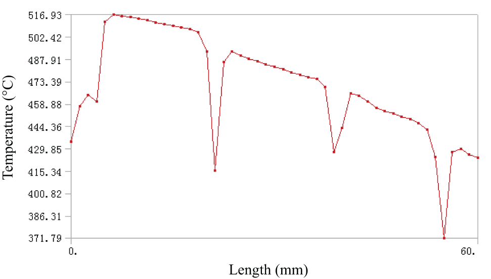
Temperature curve of the cylinder when the wind speed is 1.44 m/s.
From Figures 10–13, the temperature distribution of the outer wall, kiln crust, fireproof layer, and cylinder of the rotary kiln can be seen when the wind speed is 1.44 m/s. The four figures, respectively, show the temperature change trend of each layer and the temperature data of each segment in the rotary kiln. The maximum temperature of the kiln’s outer wall is 516.03 °C, and the lowest is 370.3 °C. The maximum temperature of the kiln crust is 1052 °C, and the lowest is 842.31 °C. The maximum temperature of the fireproof layer is 572.99 °C, and the lowest is 422.65 °C. The maximum temperature of the cylinder is 516.93 °C, and the lowest is 371.79 °C. The trends of temperature variation of four layers are more linearization.
When the wind speed is 5.32 m/s, the simulated temperature distribution nephogram of rotary kiln body is as shown in Figure 14.

Temperature distribution nephogram of rotary kiln body when the wind speed is 5.32 m/s.
From Figure 15, the temperature distribution of the outer and inner walls of rotary kiln body can be seen. In order to know the temperature distribution of each layer of kiln, temperature data curves of the outer wall, kiln crust, fireproof layer, and cylinder are extracted and shown in Figures 16–19, respectively.

Cutaway view of rotary kiln body’s temperature distribution nephogram when the wind speed is 5.32 m/s.

Temperature curve of the outer wall when the wind speed is 5.32 m/s.
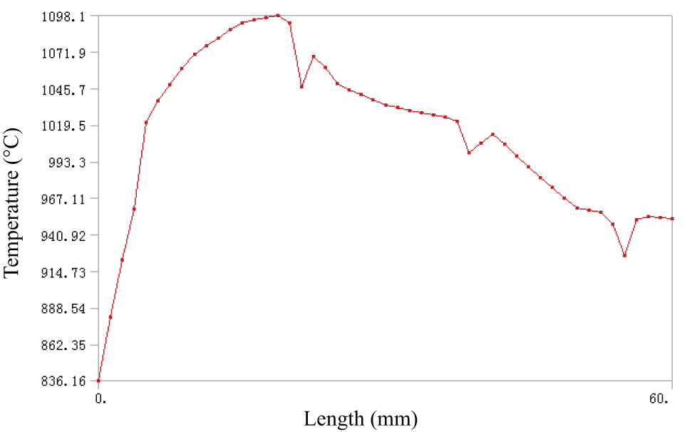
Temperature curve of the kiln crust when the wind speed is 5.32 m/s.
Temperature curve of the fireproof layer when the wind speed is 5.32 m/s.

Temperature curve of the cylinder when the wind speed is 5.32 m/s.
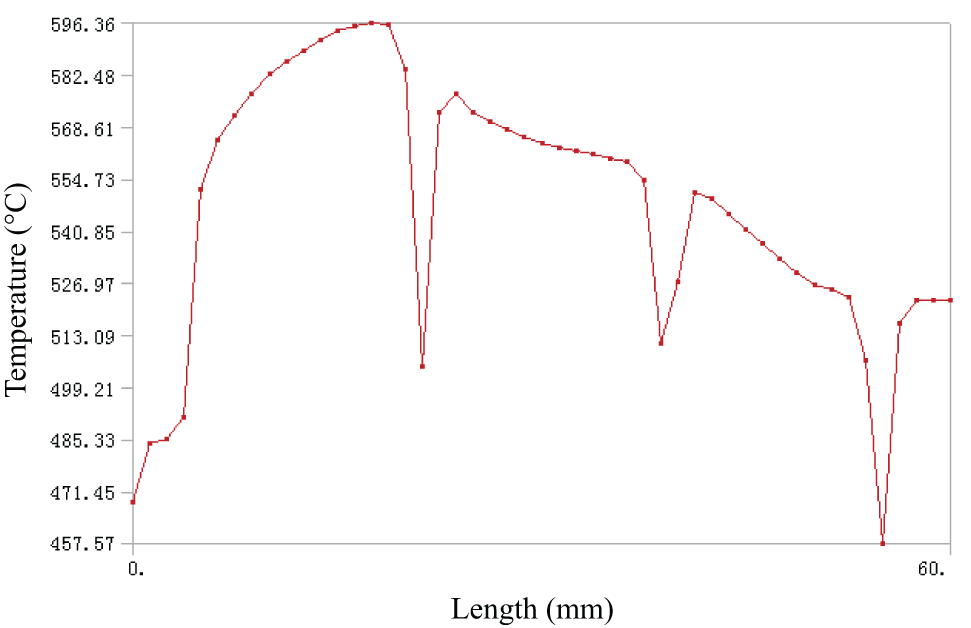
The temperature distribution of the outer wall, kiln crust, fireproof layer, and cylinder when the wind speed is 5.32 m/s can be seen from Figures 16–19, respectively. The four figures, respectively, show the temperature changing trend of each layer and temperature data of every segment in the rotary kiln. The maximum temperature of the kiln’s outer wall is 536.33 °C, and the lowest is 400.55 °C. The maximum temperature of the kiln crust is 1098.10 °C, and the lowest is 836.16 °C. The maximum temperature of the fireproof layer is 596.36 °C, and the lowest is 457.57 °C. The maximum temperature of the cylinder is 537.17 °C, and the lowest is 402.18 °C. The temperature curves are relatively smooth in addition to mutations in the four-wheel position.
Comparing analysis results of two different wind speeds, the rotary kiln body’s temperature of each layer is relatively high and the temperature curve is more approximate to curve and temperature changes are more stable when speed is larger.
The effect of the wind speed on the temperature field must change the stress field. Thermal stress nephograms of the rotary kiln in two different wind speeds are shown in Figures 20 and 21, respectively. In Figure 20, when the wind speed is 1.44 m/s, the maximum stress is 387.5 MPa and its location is the contact of the cylinder and the second wheel. The minimum stress is 0.194 MPa, which appears at the leftmost end of the cylinder. It is shown in Figure 21 that the maximum stress is 412.38 MPa when the wind speed is 5.32 m/s and its location is the contact of the cylinder and the second wheel. The minimum stress is 0.154 MPa, which appears in the cylinder at the second wheel.

Stress field nephogram of rotary kiln when the wind speed is 1.44 m/s.

Stress field nephogram of rotary kiln when the wind speed is 5.32 m/s.
Compared with two figures, it can be found that the rotary kiln’s thermal stress is greater when the wind speed is larger. The changes in the wind speed lead to different positions of maximum thermal stress and minimal thermal stress in rotary kiln body. Big mutation of stress locates in the contact of the wheel and cylinder. And the change in the wind speed cannot improve the stress concentration phenomenon effectively.
Influence of cooling fan outside the kiln on rotary kiln temperature field and stress field
In order to prevent the heat expansion and cold contraction of the rotary kiln, the temperature of the rotary kiln’s outer wall should not be too high; generally, it should not be more than 400 °C. The rotary kiln mostly adopts air cooler for cooling in industry; the different setting of air cooler volume and quantity will change the body temperature of the rotary kiln. Different wind speeds directly affect the size of the coefficient of heat transfer in the outer wall; a set of measured data 12 of surface comprehensive coefficient of heat transfer is cited to analyze with different temperatures and wind speeds of the cylinder and wheel.
From the previous analysis, the temperature difference between the cylinder and wheel is about 100 °C. Combined with data in Table 3, the comprehensive coefficient of heat transfer is 33.98 and 37.51 when the wind speed is 20 and 28 m/s, respectively. Then, the two sets of data are used for contrast analysis.
Comprehensive coefficient of heat transfer on the kiln surface with different temperatures and wind speeds.

When the comprehensive coefficient of heat transfer is 33.98, the simulated temperature distribution nephogram of the rotary kiln body is as shown in Figure 22. Figure 23 is a cutaway view of the kiln body’s temperature distribution nephogram.

Temperature distribution nephogram of rotary kiln body when comprehensive coefficient of heat transfer is 33.98.

Cutaway view of rotary kiln body’s temperature distribution nephogram when comprehensive coefficient of heat transfer is 33.98.
In Table 3, T represents the temperature difference (unit of T: °C). V represents the wind speed (unit of V: m/s). The unit of coefficient of heat transfer is
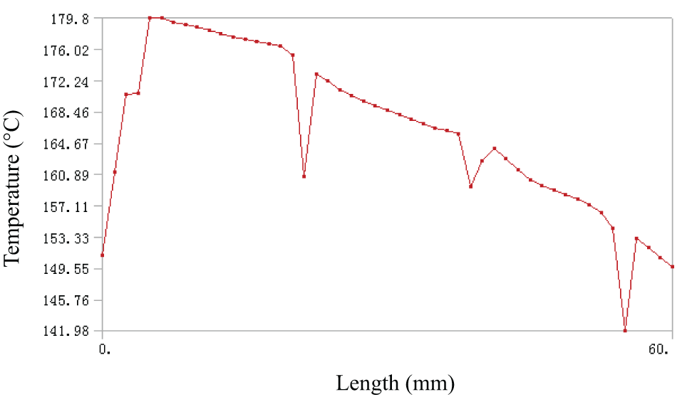
Furthermore, the temperature curves of the outer wall, kiln crust, fireproof layer, and cylinder are extracted; they are shown in Figures 24–27, respectively. From Figures 24–27, the temperature distribution of the outer wall, kiln crust, fireproof layer, and the cylinder when the comprehensive coefficient of heat transfer is 33.98 can be seen. The four figures show the temperature change trend of each layer and the temperature data of each segment in kiln, respectively. The maximum temperature of the kiln’s outer wall is 178.5 °C, and the lowest is 140.4 °C. The maximum temperature of the kiln crust is 906.56 °C, and the lowest is 721.73 °C. The maximum temperature of the fireproof layer is 254.65 °C, and the lowest is 205.73 °C. The maximum temperature of the cylinder is 179.87 °C, and the lowest is 141.98 °C.

Temperature curve of the outer wall when comprehensive coefficient of heat transfer is 33.98.

Temperature curve of the kiln crust when comprehensive coefficient of heat transfer is 33.98.

Temperature curve of the fireproof layer when comprehensive coefficient of heat transfer is 33.98.
Temperature curve of the cylinder when comprehensive coefficient of heat transfer is 33.98.
When the comprehensive coefficient of heat transfer is 37.51, the simulated temperature distribution nephogram of rotary kiln body is as shown in Figure 28. Figure 29 is a cutaway view of the kiln body’s temperature distribution nephogram.

Temperature distribution nephogram of rotary kiln body when comprehensive coefficient of heat transfer is 37.51.

Cutaway view of rotary kiln body’s temperature distribution nephogram when comprehensive coefficient of heat transfer is 37.51.
Furthermore, the temperature curves of the outer wall, kiln crust, fireproof layer, and cylinder are extracted; they are shown in Figures 30–33, respectively. From Figures 30–33, the temperature distribution of the outer wall, kiln crust, fireproof layer, and cylinder when the comprehensive coefficient heat transfer is 33.98 can be seen. The four figures show the temperature change trend of each layer and the temperature data of each segment in kiln. The maximum temperature of the kiln’s outer wall is 166 °C, and the lowest is 132 °C. The maximum temperature of the kiln crust is 901.28 °C, and the lowest is 717.38 °C. The maximum temperature of the fireproof layer is 242.9 °C, and the lowest is 198.31 °C. The maximum temperature of the cylinder is 167.29 °C, and the lowest is 134.15 °C.

Temperature curve of the outer wall when comprehensive coefficient of heat transfer is 37.51.

Temperature curve of the kiln crust when comprehensive coefficient of heat transfer is 37.51.

Temperature curve of the fireproof layer when comprehensive coefficient of heat transfer is 37.51.

Temperature curve of the cylinder when comprehensive coefficient of heat transfer is 37.51.
From the above analysis, it is found that the temperature of rotary kiln body in each layer is relatively low when the comprehensive coefficient of heat transfer is larger, so the size of the comprehensive coefficient of heat transfer has not much impact on temperature trends of the layers. Thus, the cylinder temperature can be reduced by increasing the comprehensive coefficient of heat transfer of the outer surface, and the most direct measure is to increase the cooling fan speed of the outer wall, but the drawback of this measure is that there would be more energy consumption. 13
The temperature field changes must lead to the stress field change; stress field nephogram of rotary kiln body is simulated under the condition of two different comprehensive coefficients of heat transfer, as shown in Figures 34 and 35, respectively.

Thermal stress distribution nephogram of rotary kiln body when comprehensive coefficient of heat transfer is 33.98.

Thermal stress distribution nephogram of rotary kiln body when comprehensive coefficient of heat transfer is 37.51.
The maximum stress of the rotary kiln is 260.2 MPa, and the minimum stress is 0.927 MPa as shown in Figure 34. The maximum stress of the rotary kiln is 246.25 MPa, and the minimum stress is 0.73 MPa as shown in Figure 35. Because the ventilation conditions of the end are different with the cylinder surface, both the maximum stress and the minimum stress occur at the end of the rotary kiln, and the stress distribution on the kiln body is relatively uniform. Comparing the two figures, it can be found that the kiln body stress is smaller when the surface comprehensive coefficient of heat transfer is larger, and it can improve the ventilation conditions of rotary kiln outer surface to reduce the thermal stress. Meanwhile, the rotary kiln works with thermal stress; it will produce a certain amount of axial extension, so kiln ends should reserve a certain space and cannot be completely fixed.14,15
Optimization analysis of rotary kiln structure
Optimization of kiln crust structure
Since the temperature of the inner wall is changeable along the furnace’s length direction of the rotary kiln, as mentioned above, the same crust thickness of the rotary kiln will lead to the unreasonable distribution of the outer surface temperature. To improve this condition, first, the variable thickness of kiln structure should be taken into consideration. Then, the influence of two kinds of factors that affect the outer wall temperature should be analyzed by simulating. So, the optimal thickness of kiln can be determined.
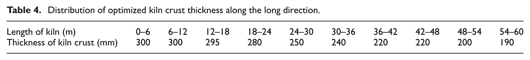
The thickness of the kiln crust has a larger influence on heat condition of the rotary kiln; the thicker the kiln crust, the smaller the radial temperature gradient of kiln body. Also, the thermal stress is smaller while the kiln’s crust is too thick. 16 The production benefit of clinker kiln will be reduced. So, choosing a reasonable thickness of the kiln is not only beneficial to improving the condition of the kiln’s outer wall temperature but also can improve the production quality of the rotary kiln. Combining the airflow distribution curve of internal rotary kiln with Figure 5 which shows the influence of the thickness of the kiln crust and the temperature of the inner wall on the temperature of the outer wall, the weight of the rotary kiln should be reduced as far as possible on the condition of guaranteeing the normal calcination conditions. A more appropriate kiln crust thickness distribution along the direction of the kiln long is shown in Table 4. 17
Distribution of optimized kiln crust thickness along the long direction.
The optimized 3D model of the rotary kiln is established by using the thickness of the kiln crust in Table 4. To prevent stress concentration, a smooth transition should be used where the thickness of the kiln crust suddenly changed. The simulated temperature distribution nephogram of the rotary kiln is shown in Figure 36, and the change curve of rotary kiln temperature in the outer wall of the rotary kiln is shown in Figure 37. It can be seen from Figure 37, except for the temperature around the four wheels which suddenly changed, that the temperature distribution in the rest of the place is uniform, and the highest temperature is 400 °C, which fulfills the prospective goal.
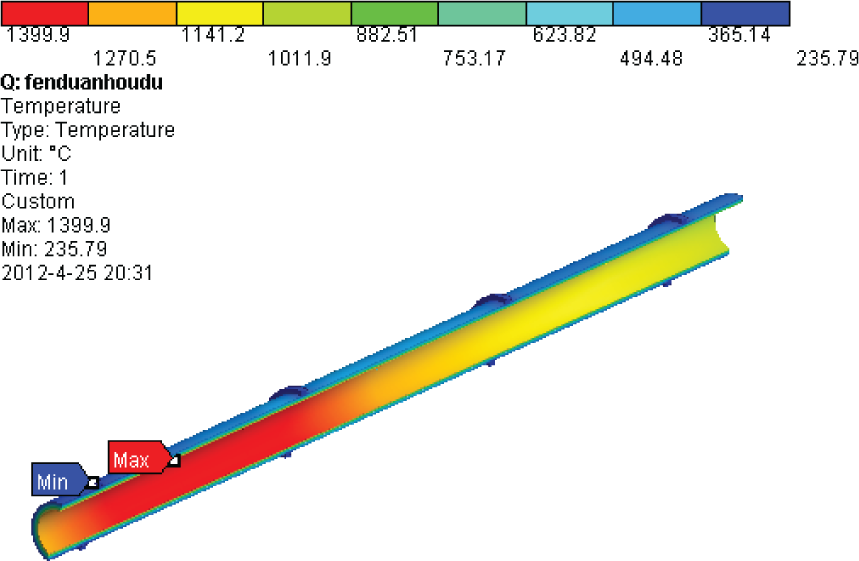
Cutaway view of temperature distribution nephogram with optimal kiln crust.

Temperature curve of the outer wall with optimal kiln crust structure.
Optimization of cylinder structure
It can be seen from the stress diagram that the maximum stress is on the contact between the wheel and cylinder, and there might be strength problem. To solve this problem, a liner can be added between the wheel and cylinder. The materials of cylinder liner can use the same material as rotary kiln cylinder or other materials with better comprehensive properties. Figure 38 shows the cylinder structure before optimization, while Figure 39 shows the optimal cylinder structure. 18
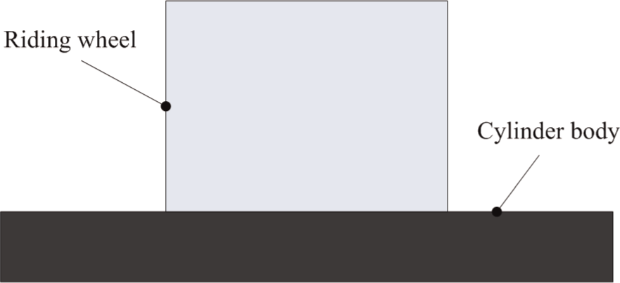
Cylinder structure before optimization.

Optimal cylinder structure.
The finite element models of the two structures are, respectively, set up; the materials of the liner and cylinder are the same in this study. Under the same working conditions, the results are as shown in Figures 40 and 41, respectively; before optimization, the maximum principal stress is 308.95 MPa while rotary kiln body is heated, and it is the contact of the third wheel and cylinder. Meanwhile, the maximum principal stress is 250.21 MPa while optimal rotary kiln body is heated. It is the contact between the fourth wheel and cylinder. The extreme stress gets obvious improvement and optimization; the maximum stress had moved to the fourth wheel, where the cylinder structure is relatively thick. This optimization efficiently solves the strength problem.

The stress nephogram before optimization.
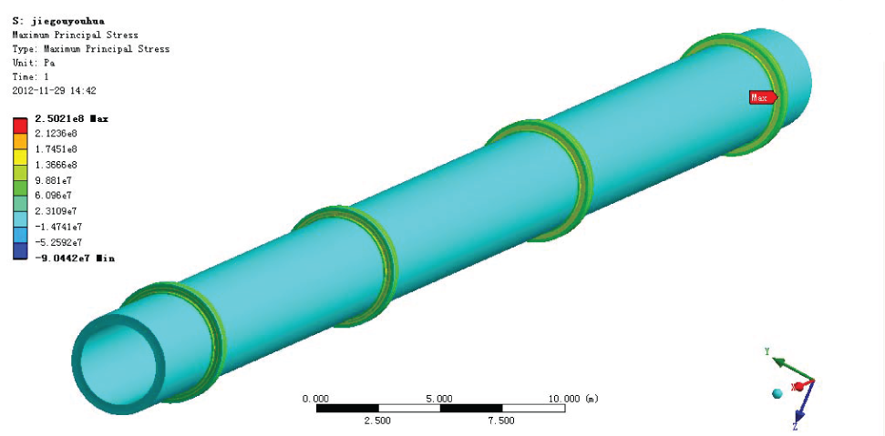
The stress nephogram of optimized cylinder structure.
There are a variety of measures to optimize the cylinder structure. For example, using the circumferential spring connection to make the cylinder free from contact with wheel can also reduce the stress. But this improvement method will increase the manufacturing cost of the rotary kiln.
Conclusion
Aiming at poor working conditions, complicated heat transfer way, temperature is difficult to control and serious energy waste problem of the rotary kiln, heat and stress analysis are carried on by using computer-aided software, some improvement measurements are put forward, and the work stability of rotary kiln is improved. Through the establishment of numerical model of the rotary kiln, temperature field, stress distribution of rotary kiln body, and relevant influence factors are analyzed. The 3D surface plot is obtained, which is the rotary kiln outer wall’s temperature change with variation in kiln crust thickness and inner wall’s temperature. It provides referential basis for the virtual design and structure optimization of the rotary kiln. The variable thickness of kiln structure improvement measures is put forward, the thickness of the kiln crust is optimized, and the outer wall’s temperature distribution of the rotary kiln has reached the ideal effect. The cylinder structure improvement measures are put forward, so the stress distribution in the rotary kiln has greatly improved. The results can contribute to reducing inputs of rotary kiln design, saving production cost, reducing the energy consumption, and providing some guidance for the reasonable distribution of the rotary kilns.
Footnotes
Academic Editor: Hakan F Oztop
Declaration of conflicting interests
The authors declare that there is no conflict of interests regarding the publication of this article.
Funding
This research was supported by National Natural Science Foundation of China (71271160), China Scholarship Council (CSC), Hubei Key Laboratory for Efficient Utilization and Agglomeration of Metallurgic Mineral Resources, and the “Twelfth Five-Year” National Science and Technology support program (2011BAB05B02).