
Abstract
Lightweight and safety performance of automobiles are two important factors for automobile designs. In this article, a research on lightweight and crashworthiness of automotive bumper has been conducted. The carbon fiber–reinforced plastic bumper beam is considered to replace the traditional high-strength steel one. The low-velocity impact finite element simulations for the above two bumper beams are performed via LS-DYNA. Furthermore, the energy absorption capabilities and dynamic response characteristics of the carbon fiber–reinforced plastic bumper beam are investigated and compared with the steel one. The results show that the carbon fiber–reinforced plastic bumper beam is of the better energy absorption capabilities and dynamic response characteristics than those of the steel one; the weight has decreased remarkably close to 50%. Meanwhile, the effect of lay-up and wall thickness on the crashworthiness of the carbon fiber–reinforced plastic bumper beam under low-velocity impact is also studied in this article to select appropriate design schemes.
Introduction
Currently, there are two kinds of materials used for manufacturing automotive bumper beams, namely, metal materials such as high-strength steel, aluminum alloy, and magnesium alloy and non-metallic materials such as glass mat thermoplastic (GMT) and sheet molding compound (SMC). To attain lightweight as well as strength requirements, one way of automotive bumper lightweight design is to vary the structure of high-strength steel bumper beam, and another is to replace traditional metal materials with light materials. 1 In fact, aluminum alloy and other light metal have some disadvantages such as high cost, low press formability, adhesion (welding) problems, and difficulty with surface treatment. 2 Conversely, composite materials, as another kind of important lightweight automobile materials by virtue of excellent properties, have gradually extended their application in many vehicle models.1,3–5
Several studies on composite bumper beams have been conducted. For example, Belingardi et al. 6 compared the energy absorption capabilities of bumper beam made of E-Glass/epoxy pultruded composites with steel and E-Glass/epoxy fabric composites subjected to low-velocity impact. Rao and Murthy 7 studied the stress, displacement, and strain of alloy; expanded poly propylene (EPP); and GMT under high-velocity impact in order to find the best material with the highest material strength and structure. Marzbanrad et al. 8 investigated a front bumper beam made of three materials: aluminum, GMT, and high-strength SMC by impact modeling to determine the deflection, impact force, stress distribution, and energy absorption behavior to find the best choice of material, shape, and thickness. Davoodi et al.9,10 compared the mechanical properties and impact capabilities of hybrid kenaf/glass-reinforced epoxy composite with GMT to explore the possibility of the natural fiber composite materials’ application to bumper beam.
Carbon fiber–reinforced plastic (CFRP) has lots of advantages such as low density, high specific strength and specific stiffness, strong corrosion resistance, ability to relieve and absorb a quantity of impact energy, highly design flexibility, and possibility to achieve the optimal mechanical properties and processing performances through rational allocation of material components. Performances of carbon fiber–reinforced epoxy (a kind of CFRP), glass fiber–reinforced polyester, and several kinds of metals are shown in Table 1. 11 For instance, replacing steel with the density of 7.8 g/cm3 by carbon fiber–reinforced epoxy with the density of 1.6 g/cm3 may enhance the strength and stiffness, as well as lighten the weight by the proportion of 40%−60%. 12 In recent years, CFRP is widely used in the drive shafts, brake blocks, tail fins, engine hoods, interior trimmings, and other parts of high-grade vehicles, 13 while is quite poorly used in bumper beams. Therefore, it is fairly significant to compare the impact properties of CFRP with that of traditional high-strength steel so as to investigate whether CFRP is a kind of suitable material for automotive bumper beams.
Certain performances of carbon fiber–reinforced epoxy, glass fiber–reinforced polyester, and several kinds of metals.

Furthermore, the designability of CFRP for automotive bumper beams is also explored in this article. As a composite material, the multiplicity of lay-up may influence the energy absorption properties. Several researchers have studied the effect of lay-up on the impact properties of composite shell-type structure. Krishnamurthy et al. 14 investigated the effect of ply orientation on impact response and damage in laminated composite cylindrical shell and found out that both the contact force and damage of the [0/90/0/90]s laminate were larger than those of the [45/−45/45/−45]s laminate. Kim et al. 15 considered the impact response of cylindrical composite shells with three stacking sequences of [04/904/904/04], [904/04/04/904], and [454/−454/−454/454]; and the contact force in a certain curvature was [454/−454/−454/454] < [904/04/04/904] < [04/904/904/04]. Huang and Lee 16 investigated the impact damage of two stacking sequences, [90/0]4s and [45/45]4s, and found out that the damage increased with global shell stiffness, which was “cross-ply” > “angle-ply.” Gning et al.17,18 observed and analyzed the damage development in thick composite tubes with only ±55° layers through a drop weight test. Shi et al. 19 compared energy absorption capabilities of carbon fiber–reinforced epoxy composite cylinders with five stacking sequences of [0/90/0/90/0]s, [0/90]5, [55/−55/55/−55/55]s, [55/−55/55/0/90]s, and [553/−553/55/−55/0/90], in which [553/−553/55/−55/0/90] was of the best impact resistance. As another thin-walled structure, CFRP square tube structure can be inspired by these former investigations in the lay-up design. The wall thickness, as a main structural parameter, is another influencing factor for energy absorption properties of the CFRP bumper beam. And the specific influence of wall thickness is also discussed in this article.
The automotive bumper system plays a major role of protector under low-velocity impact. As for a good design of a bumper system, the impact energy is essentially absorbed by the bumper system’s (beam and crash box) deformation to guarantee the intactness of other structural parts.20,21 This article aims to study the energy absorption capabilities and dynamic response characteristics of the frontal bumper beam and crash boxes under low-velocity impact.
Low-velocity impact simulation of the high-strength steel bumper beam
Finite element model
The prototype of the bumper beam in this article came from certain current vehicle model. With a closed square section structure, it is superior for its great impact energy absorption properties. 22 And the structural dimensions of the impactor were determined based on the Standard GB17354-1998. 23
In the article, the nonlinear explicit dynamic model was adopted for the simulation analysis. For thin-walled structures (with the wall thickness of 1.76 mm) such as bumper beam and crash box, the Thin Shell 163 element and default Belytschko–Tsay element formulation were adopted. The impact system established in ANSYS comprises three parts, that is, a deformable bumper beam, two rigid crash boxes, and a rigid impactor. The above system was divided into 17,518 elements in all, as shown in Figure 1. A certain mass was rigidly attached to the two rear extremities of the crash boxes to attain the gross mass of 1100 kg of the bumper system in order to simulate the vehicle mass. According to GB17354-1998, the mass of impactor should be equal to the whole vehicle; thus, lumped mass was attached to the central location of the back of the impactor to make its gross mass equal to 1100 kg.
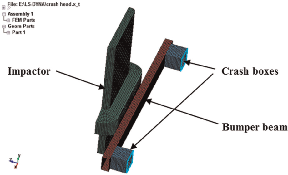
Finite element model of the impact system.
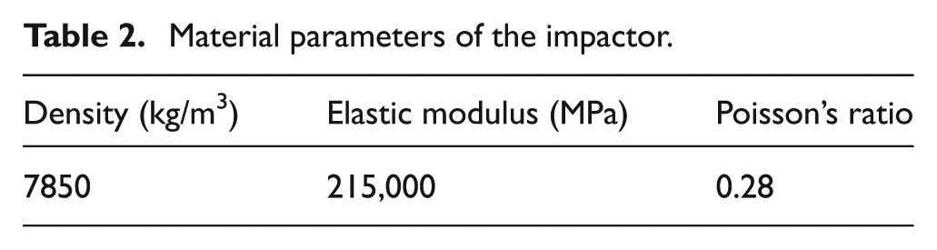
Then keywords outputted from ANSYS were required to be modified in LS-PrePost. The material models of the impactor, beam, and crash boxes were defined (material parameters of the impactor and bumper system were shown in Tables 2 and 3, respectively). Contact type of impactor with the bumper beam was set as automatic single surface contact and a Z-direction initial velocity of −1.1 m/s (−4 km/h) of the impactor was set to make it crash into the bumper beam, according to GB17354-1998. In addition, the degree of freedom (DOF) of vertical direction was restrained while the DOF of horizontal direction was remained. Then the time with zero contact force was set as the impact termination time. The termination time was preset as 100 ms and the program would automatically terminate when zero contact force was triggered. The simulation results that were solved in LS-DYNA would be inspected and analyzed.
Material parameters of the impactor.
Material parameters of the steel bumper beam and crash box.

Simulation results and analysis
The energy versus time plot of the total system is shown in Figure 2. In the process of impact, the total energy of the system is almost unchanged, which is 665.44 J initial kinetic energy of the impactor. The bumper beam deforms with the impact process evolving. The kinetic energy is transformed into deformation energy, which leads to an increase in the internal energy of the total system. On the other hand, the curve of kinetic energy of the total system indicates a rapidly declining trend. When the impact has lasted for 0.0315 s, internal energy of the total system reaches to the peak, that is to say the energy absorbed by bumper system’s deformation is the largest at this time, up to 327.2 J, 49.2% of the total energy. Conversely, the kinetic energy of the total system is at the minimum this moment, which reveals that the bumper system achieves relatively sufficient energy absorption. Till the impact process completes, the ultimate energy absorbed by the bumper system reaches 191 J due to the permanent plastic deformation.

Energy versus time plot of the total system.
Dynamic response, including the displacement, velocity, acceleration, and force change of the bumper beam, is also analyzed. The simulation results show that the impact process completes at about 0.051 s. At t = 0.03 s, the bumper beam gets maximum deformation. The relative displacement from the node 5046 with maximum deformation to the node 3876 with minimum deformation on the beam is taken as the actual deformation of the beam. The contour map of deformation at t = 0.03 s and deformation versus time plot of the bumper beam are shown in Figures 3 and 4, respectively. The velocity history of the impactor and bumper system, the contact force history, the acceleration history of the impactor, and the acceleration history of the bumper beam are shown in Figures 5–8, respectively.

Contour map of deformation of the bumper beam at t = 0.03 s.

Deformation versus time plot of the bumper beam.

Velocity history of the impactor and bumper system.
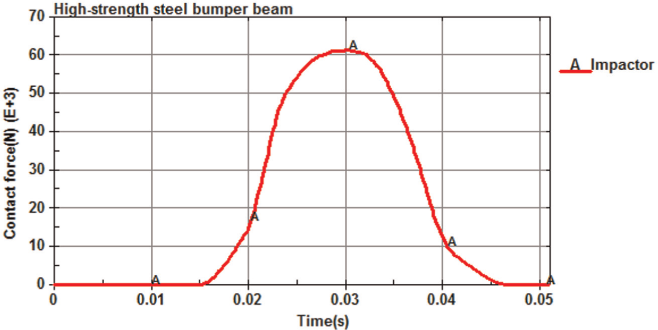
Contact force history of the impactor.

Acceleration history of the impactor.

Acceleration history of the bumper beam.
The maximum deformation of the bumper beam occurs at t = 0.03 s with a value of 0.0126 m, which is permitted since it does not surpass the permissive displacement of 0.050 m between the bumper beam and radiator in this study.
It is shown in the velocity history plot that the impactor crashes into the bumper system with an initial velocity of −1.1 m/s and then tends to be stable at about 0.046 s. The velocity of the bumper beam goes up from 0 and also stabilizes at about 0.046 s. The impact process ends with an ultimate velocity of −0.197 m/s of the impactor and −0.903 m/s of the bumper system. The coefficient of restitution can be calculated by the following equation

where
The contact force between the impactor and bumper system reaches its peak at about 0.03 s with a value of 61.610 kN and changes to 0 at about 0.046 s when the impact is terminated. The variation tendency of the impactor acceleration directly corresponds to contact force. The acceleration of bumper beam shows a vibratory change law because of its elastic and plastic deformation characteristics. Its maximum instantaneous acceleration reaches 311.87 m/s2.
Low-velocity impact simulation of the CFRP bumper beam
Finite element model
Carbon fiber–reinforced epoxy T300/5208 was used in this study. With a single layer thickness of 0.3 mm, T300/5208 has excellent mechanical properties, such as high specific strength (about 4.8–7.2 times that of steel), high specific modulus (about 3.1–4.2 times that of steel), low density, and strong corrosion resistance and impact resistance. 24 The material parameters of T300/5208 are listed in Table 4. 25
Material parameters of T300/5208.
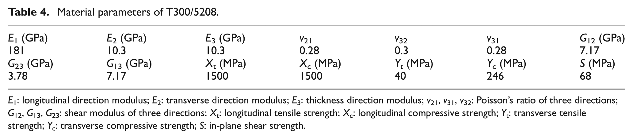
E 1: longitudinal direction modulus; E 2: transverse direction modulus; E 3: thickness direction modulus; v 21, v 31, v 32: Poisson’s ratio of three directions; G 12, G 13, G 23: shear modulus of three directions; X t: longitudinal tensile strength; X c: longitudinal compressive strength; Y t: transverse tensile strength; Y c: transverse compressive strength; S: in-plane shear strength.
Finite element model of the CFRP bumper system was based on the original steel bumper system model. The structural dimension of the crash box was constant and cross-sectional dimensions and the length of the beam were as same as the traditional high-strength steel one. The wall thickness of the bumper beam was designed bigger as the stiffness of CFRP is lower than high-strength steel given the same volume. Here, the wall thickness of the CFRP beam was preliminarily set as 3.6 mm, approximately twice that of the high-strength steel beam, which was about 12 layers’ thickness of T300/5208.
In this study, the No. 59 material model in LS-DYNA was applied to simulate CFRP material. The laminate structure was simulated by increasing integral points, which were equal to the actual number of layers on the thickness of shell element. Each point represented one layer of the CFRP-laminated structure, and thickness and ply angle of each layer needed to be set.
Simulation of CFRP beams with different lay-up schemes
Lay-up design is a critical factor contributing to crashworthiness of the CFRP-laminated structure under low-velocity impact, as the references Krishnamurthy et al., 14 Kim et al., 15 Huang and Lee, 16 Gning et al.,17,18 and Shi et al. 19 mentioned. The above researches have investigated mainly 0°, 90°, ±45°, and ±55° ply angles, including orthotropic or heterotropic lay-up, cross or overlapped lay-up, and mixed lay-up of them.
This article aimed to systematically research the lay-up schemes mentioned above. Table 5 showed the five groups (A, B, C, D, and E) of lay-up schemes, in which Group A was to explore whether 0° or 90° has better crashworthiness under low-velocity impact when in the outer layer, Group B was to study the crashworthiness differences under low-velocity impact between symmetry lay-up and asymmetric lay-up, Group C was to select an appropriate proportion of 0° and 90° layers, Group D was to choose an reasonable proportion of overlapped layers, and Group E was to compare the crashworthiness under low-velocity impact of ±45° and ±55° layers in the combination with the same other layers.
Simulation results of different lay-up schemes of the CFRP bumper beam.

In the analysis on the simulation results of the above lay-up schemes with equal thickness and different ply angles, several indexes were chosen to evaluate energy absorption capabilities and dynamic response characteristics of the bumper beam subjected to low-velocity impact, namely, internal energy, peak contact force, maximum deformation, maximum acceleration, impact time, and coefficient of restitution. Table 5 shows evaluation indexes of bumper beams with both CFRP with five groups’ lay-up schemes and high-strength steel. These seven evaluation indexes manifest various change laws, in which the value of peak internal energy minus that of terminal internal energy represents energy absorption capabilities, while contact force, maximum deformation, and coefficient of restitution indicate the dynamic response characteristics.
Figures 9–11 show the internal energy–time, contact force–time, and deformation–time plot of Group A and Group B, respectively. There is little difference between A1 and A2 lay-up schemes, indicating that 0° or 90° placed in the outer layer has little connection with the crashworthiness under low-velocity impact. The same situation appears in B1 and B2 lay-up schemes, showing similar crashworthiness under low-velocity impact of symmetry and asymmetric lay-up schemes. The energy absorption of Group B is higher than that of Group A and the terminal internal energy of Group B is relatively low, which means their permanent plastic deformation is relatively small. The peak contact force of Group B is higher than that of Group A and the contact time is shorter but these two indexes of Group B are still more excellent than that of high-strength steel. The maximum deformation of Group B is obviously smaller than that of Group A, and coefficient of restitution of Group B is bigger than that of Group A, as listed in Table 5. The conclusion can be drawn that the crashworthiness under low-velocity impact of heterotropic lay-up is more excellent than that of orthotropic lay-up. Moreover, B2 lay-up scheme manifests the best impact properties among Group A and Group B.
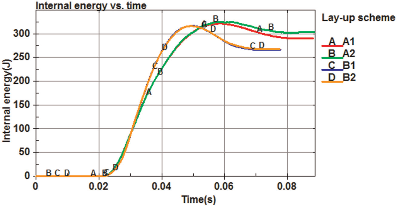
Internal energy versus time plot of the bumper system of Group A and Group B.
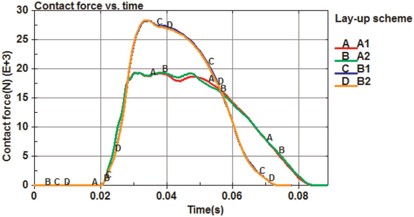
Contact force versus time plot of the impactor of Group A and Group B.
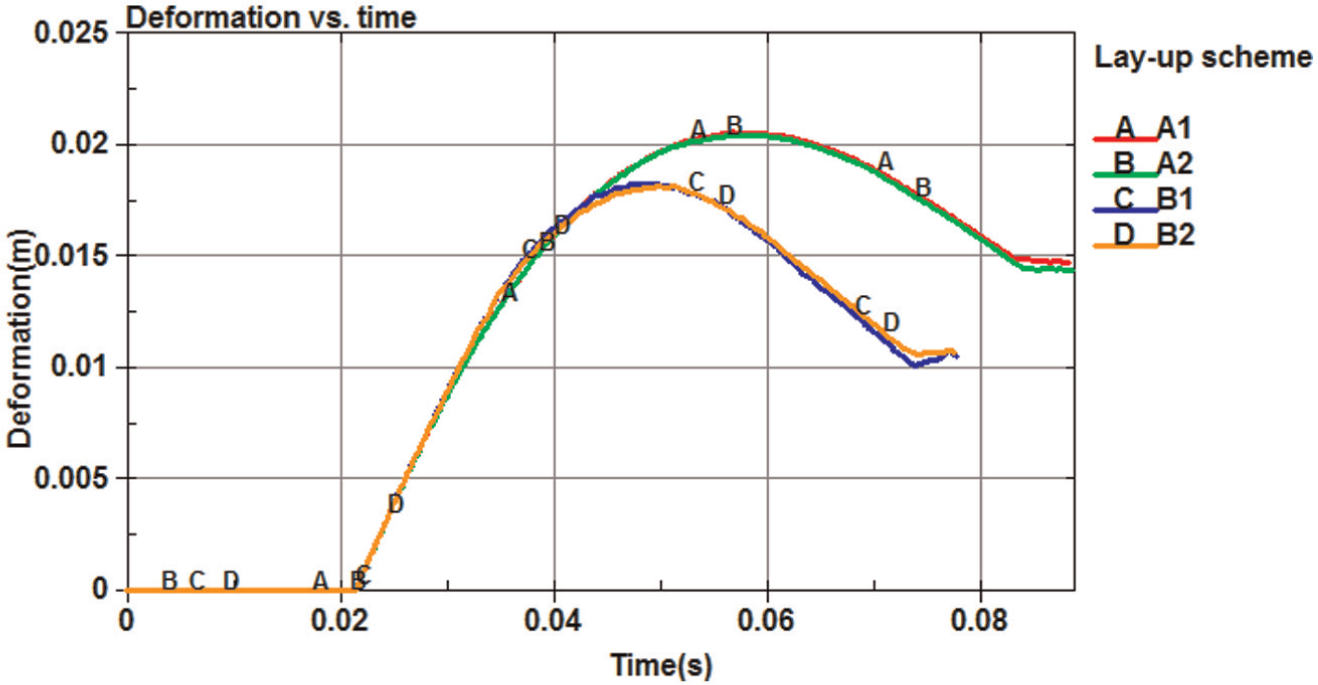
Deformation versus time plot of the bumper beam of Group A and Group B.
Then [0/90] layer group was added in heterotropic layers, as listed in Group C. Figures 12–14 show the internal energy–time, contact force–time, and deformation–time plot of Group C, respectively. The energy absorption and coefficient of restitution of C1 and C2 lay-up schemes are higher than that of others. The C2 and C3 lay-up schemes have a smaller deformation. The contact time of C2 and C3 lay-up schemes is slightly shorter than others but still longer than that of high-strength steel. Therefore, C2 lay-up scheme is the best choice in Group C from a comprehensive view, and the most appropriate proportion of [0/90] layers in mixed lay-up schemes consisting of ±45° layers and orthotropic layers are roughly between 0.17 and 0.35 (the proportion of C1–C3). After the comparison of B2 and C2 lay-up schemes, it can be found that C2 has better crashworthiness under low-velocity impact.

Internal energy versus time plot of the bumper system of Group C.
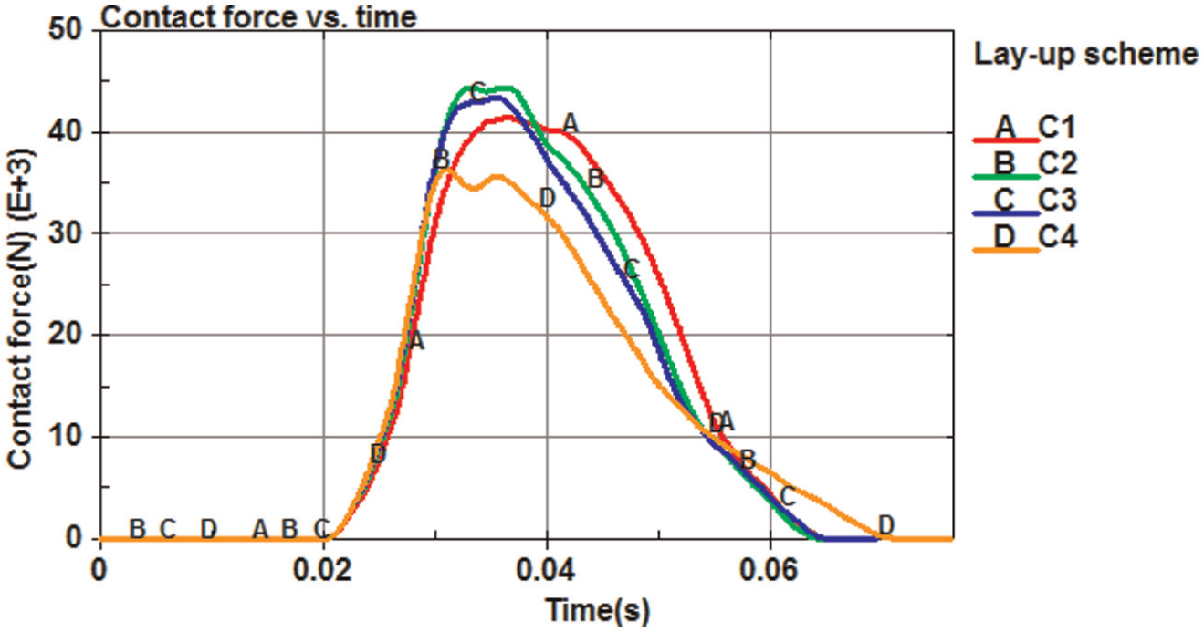
Contact force versus time plot of the impactor of Group C.

Deformation versus time plot of the bumper beam of Group C.
±45°n layers were replaced by overlapped 45°n/−45°n layers of C2 lay-up scheme, as listed in Group D. Figures 15–17 show the internal energy–time, contact force–time, and deformation–time plot of C2 and Group D, respectively. It can be found that only D1 lay-up scheme is comparative to C2 lay-up scheme.

Internal energy versus time plot of the bumper system of C2 and Group D.

Contact force versus time plot of the impactor of C2 and Group D.

Deformation versus time plot of the bumper beam of C2 and Group D.
±45° layers were replaced by ±55° layers of C2 and D1 lay-up schemes, as listed in group E. Figures 18–20 show the internal energy–time, contact force–time, and deformation–time plot of C2, D1, and Group E, respectively. It can be found that ±55° layers have no obvious advantages over ±45° layers. Although the maximum deformation of the E2 lay-up scheme is obviously small, its coefficient of restitution is insufficient compared with that of the high-strength steel beam, as listed in Table 5.
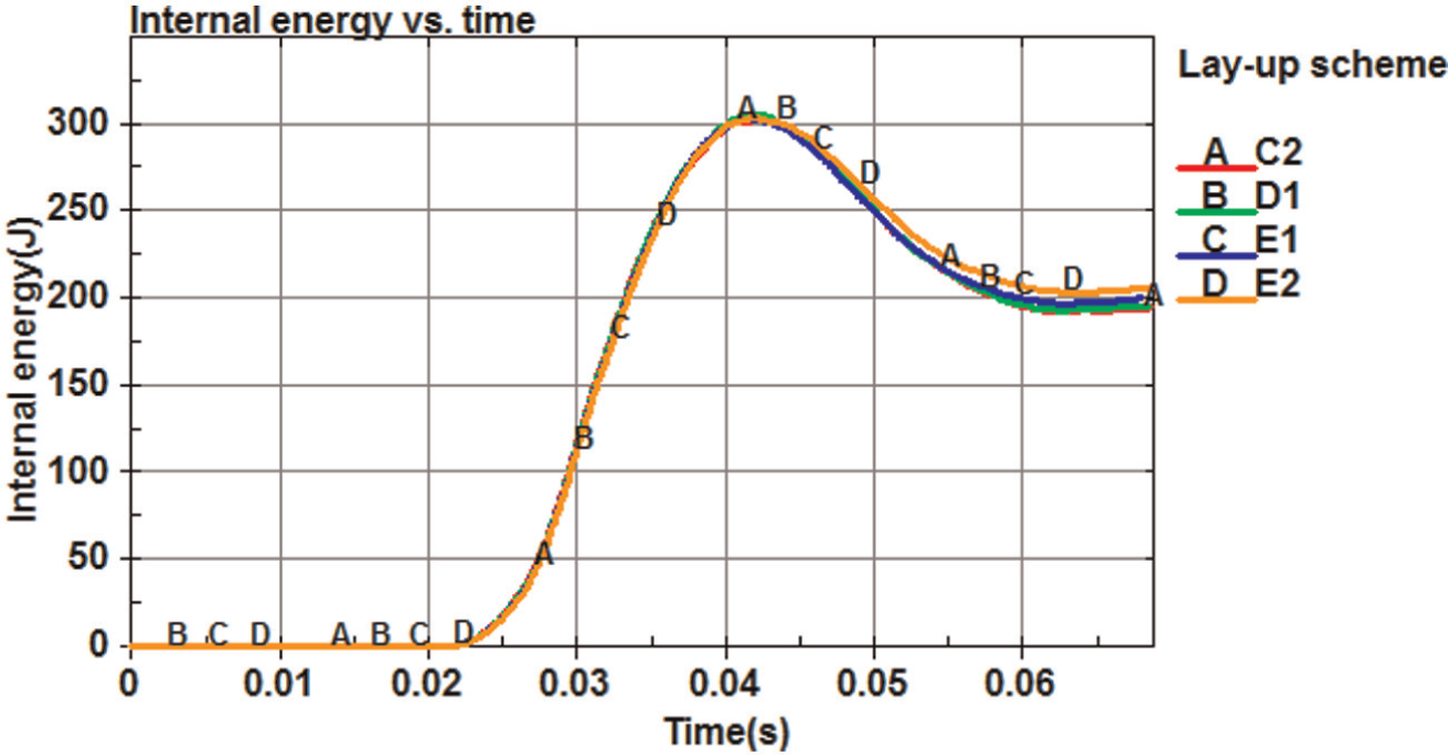
Internal energy versus time plot of the bumper system of C2, D1, and Group E.
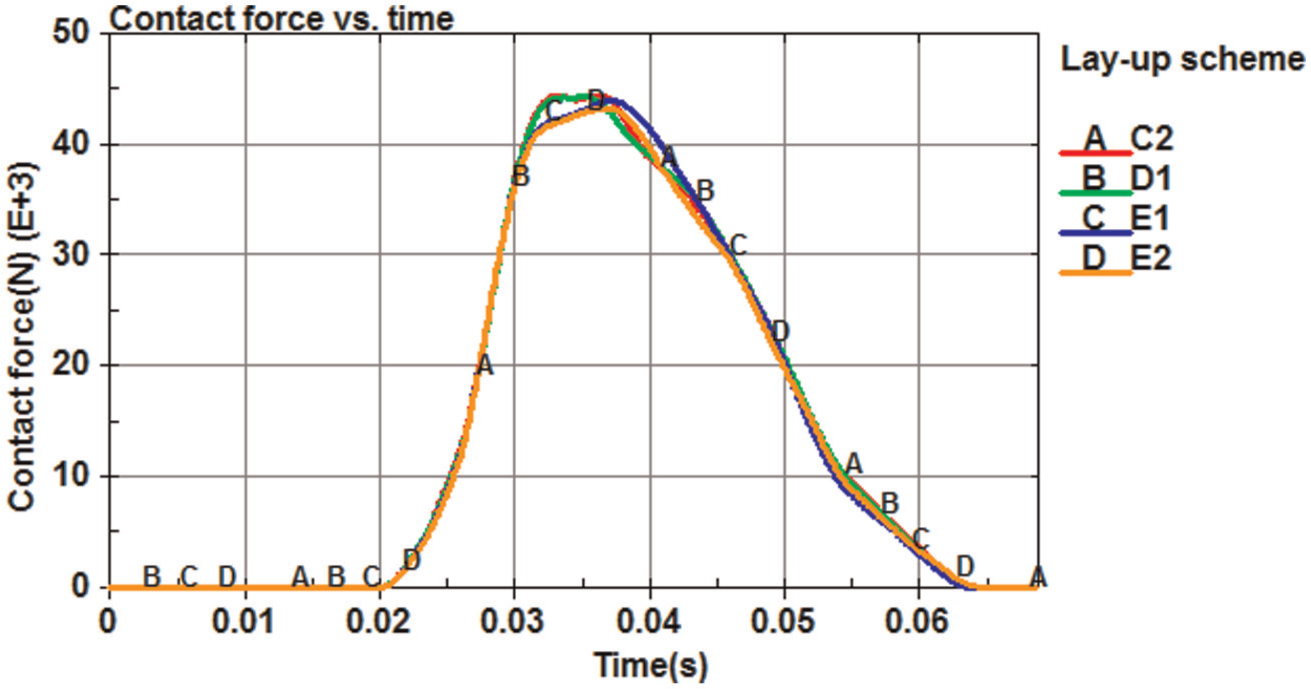
Contact force versus time plot of the impactor of C2, D1, and Group E.

Deformation versus time plot of the bumper beam of C2, D1, and Group E.
Finally, C2 lay-up scheme is chosen when the wall thickness is defined as 3.6 mm:
C2: [45/−45/45/−45/45/−45/45/−45/45/90/0/90].
Simulation of CFRP beams with different wall thicknesses
Wall thickness is another critical factor contributing to the crashworthiness of the CFRP-laminated structure under low-velocity impact. Based on the above analysis, further investigation on CFRP beams with wall thicknesses around 3.6 mm was conducted. Wall thicknesses of 3.0, 3.3, 3.9, 4.2, and 4.5 mm (namely, 10, 11, 13, 14, and 15 layers) were compared with that of 3.6 mm (namely, 12 layers). The lay-up schemes were all defined according to C2 lay-up scheme. The simulation results are listed in Table 6.
Simulation results of different wall thicknesses of the CFRP bumper beam.

The peak internal energy in these schemes is similar. Energy absorption, maximum deformation, and the coefficient of restitution are mainly compared to each other. Figures 21–23 show the change law of the three evaluation indexes with the increase in wall thickness, respectively. Wall thicknesses of 3.9 and 4.2 mm (13 and 14 layers) manifest the largest energy absorption, the smallest maximum deformation, and the largest coefficient of restitution. It can be concluded that the crashworthiness of the CFRP bumper beam under low-velocity impact does not increase along with the rise in wall thickness. When the wall thickness is below 3.9 mm, the maximum deformation reduces with the rise in thickness due to the increase in beam stiffness, which is discussed in Kim and Won 2 and Marzbanrad et al. 8 When the wall thickness surpasses 3.9 mm, the beam mass reaches a comparatively higher value, resulting in a slight increase in peak internal energy, thus the maximum deformation becomes greater with the increase in thickness.
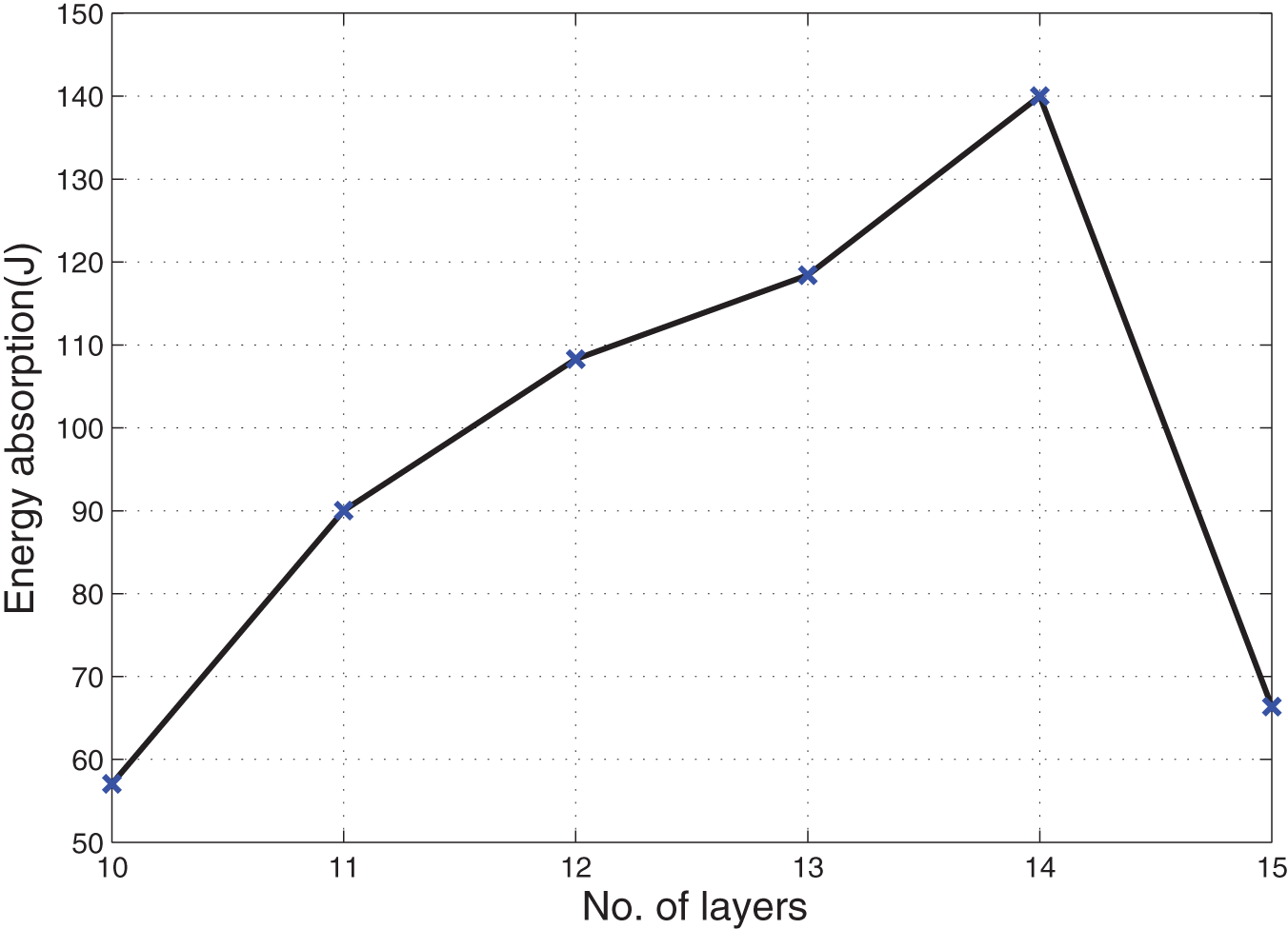
Energy absorption versus number of layers.

Maximum deformation versus number of layers.
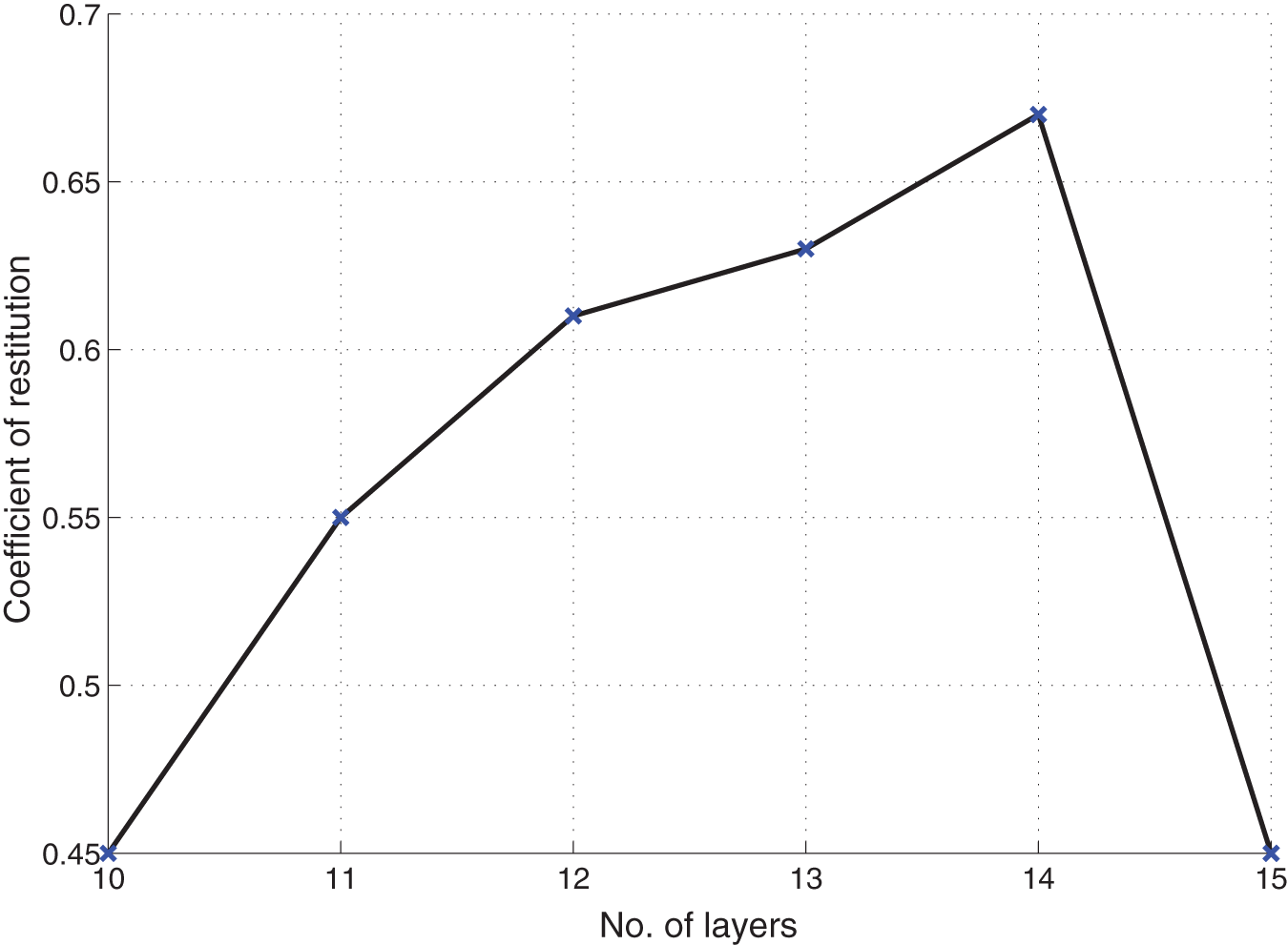
Coefficient of restitution versus number of layers.
Based on the above analysis, it is believed that the crashworthiness under low-velocity impact of design schemes as follows is relatively superior, which is the theoretical basis for the ultimate use:
13 layers: [45/−45/45/−45/45/−45/45/−45/45/0/90/0/90];
14 layers: [45/−45/45/−45/45/−45/45/−45/45/−45/0/90/0/90].
Impact properties in comparison to the high-strength steel bumper beam
By observing Tables 5 and 6, the property comparison between CFRP and high-strength steel bumper beams is as follows: the maximum value of energy absorption is approximately equivalent to that of the high-strength steel beam. The peak contact force and acceleration are far less than the latter one by and large. The contact time lasts longer, which can reduce great secondary damage to ensure the safety of passengers and bodywork. The maximum deformation is slightly larger, but still within the permitted range of 0.05 m. The only drawback of the CFRP bumper beam is inconsistency of coefficient of restitution and terminal internal energy, but they can achieve a proper value comparable to that of the steel beam by rational choice. The two adopted lay-up schemes have masses of 2.57 and 2.77 kg, respectively, which means the mass is reduced by 50% and 46% compared with that of 5.17 kg of the original high-strength steel bumper beam.
Conclusion
Well-designed CFRP bumper beams can not only obtain comparable and even superior crashworthiness under low-velocity impact as the traditional high-strength steel bumper beam but also get a mass reduction with a percentage up to 50% to attain the goal of lightweight. Hence, it is practical and prospective to apply CFRP to automotive bumper beams instead of the traditional high-strength steel.
Through the comparative analysis of the crashworthiness of bumper beams with several CFRP lay-up schemes under low-velocity impact, conclusions can be drawn that mixed lay-up schemes consisting of ±45°n layers and orthotropic layers are of better crashworthiness under low-velocity impact compared with pure orthotropic, pure heterotropic, and mixed lay-up schemes consisting of overlapped 45°n/−45°n layers and orthotropic layers or consisting of ±55° and orthotropic layers. In addition, the proportion of orthotropic layers should be in an appropriate range around 0.17–0.35.
Through the comparative analysis of CFRP bumper beams with different wall thicknesses, it is found that the crashworthiness of the CFRP bumper beam under low-velocity impact does not increase linearly with the rise in wall thickness. Instead, there exists an inflection point. With the rise in wall thickness, the characteristics of energy absorption and deformation are influenced by beam stiffness and mass, synthetically.
Footnotes
Academic Editor: Yu-Fei Wu
Declaration of conflicting interests
The authors declare that there is no conflict of interests regarding the publication of this article.
Funding
This research was supported by the Significant Science and Technology Innovation Project of Hubei Province, China (Project No. 2014AAA005) and the Independent Innovation of Foundation of Wuhan University of Technology (Project No. 2014zy065).