
Abstract
In this study, a hybrid composite material was fabricated by stacking carbon fiber–reinforced plastic on CR340 plates to increase the specific strength and specific stiffness, compared to thick boron steel plates or dual-phase steels. A deep drawing test was conducted for this hybrid composite material, using various process parameters, to assess its formability and potential use in vehicle parts. The experimental results showed that the forming depth was reduced in both CR340 and the CR340/carbon fiber–reinforced plastic composite when the blank holding force (Bf) was increased. Although the forming depth of CR340 was decreased abruptly when Bf >= 30 kN, the forming depth of the CR340/carbon fiber–reinforced plastic composite was not reduced, highlighting its superior formability compared to CR340. The forming depth for CR340 did not show significant differences with increasing punch velocity. On the other hand, the forming depth of the CR340/carbon fiber–reinforced plastic composite decreased with increasing punch velocity. As the punch velocity increased, carbon fiber–reinforced plastic flowed abruptly toward the round part of the die. The thinning rate in each position of the drawing product and the problems encountered during the deep drawing process were reviewed by a comparison of the experimental results.
Introduction
Recently, in the automotive industry, there has been increasing demand for environmentally friendly materials for lightweight vehicles to improve their safety and fuel efficiency and reduce environmental contamination. With the increased demand for technology development to improve the performance and efficiency of vehicles, there has been progress in the application of vehicle parts manufactured using hot pressing for advanced high-strength steel. 1,2 In addition, research and development to achieve improved fuel efficiency are underway through additional weight reductions using tailor welded blank (TWB) and partial quenching technology. 3,4
Although environmental regulations have become more stringent in the automotive industries, automotive manufacturers all over the world have focused on developing environmentally friendly vehicles, including biotechnology, natural fuel, hybrid, electric, and fuel cell vehicles. Unfortunately, the weight of environmentally friendly vehicles has increased due to the additional parts needed, such as motors, batteries, and electronic devices. Reducing their weight is the key to increasing the fuel efficiency of environmentally friendly vehicles. On the other hand, there are limitations in reducing the weight of vehicles using only advanced high-strength steel materials and TWB technology. Therefore, the application of lighter materials with better specific strength and stiffness values than existing steel materials is needed for future types of vehicles.
Accordingly, significant advances have been seen in the development of the next generation of materials, including high-strength aluminum alloys, magnesium, and fiber-reinforced composites. Among these materials, carbon fiber–reinforced plastic (CFRP) has an excellent specific strength and specific stiffness, and many studies on CFRP are currently underway. 5,6 On the other hand, CFRP composites have many limitations that impede their use as car parts, including their low elongation rate and low fracture toughness when vehicles crash. To resolve these issues, many studies on hybrid composite materials are underway to overcome the limitations of single materials by joining CFRP and a metallic material. 7,8
Teng et al. 9 studied the fracture mode according to the joining characteristics of CFRP in a metal structure reinforced by CFRP. Narmashiri et al. 10 examined the effects of joining a CFRP plate to an I-beam on the increases in the bending load, deformation restriction, and shear strain. El-Tawil et al. 11 reported that a metal hinge wrapped with CFRP showed a good fatigue cycle under low-frequency restricted partial buckling and delayed torsion. Hankeln and Mahnken 12 evaluated the formability of a single material CFRP using a simulation. During the evaluation process, they designed CFRP separately as a reinforcing material and matrix and examined the anisotropy of its strain behavior according to the viscosity and temperature. Unidirectional CFRP, however, showed anisotropy, making it unsuitable to use for vehicle parts, which need to react to crashes from several directions. In addition, to use CFRP as a hybrid composite material with metallic materials, it is necessary to perform more research on the bonding of the composite and its formability, in relation to process parameters such as the blank holding force during plate forming.
In the center pillar for vehicle parts, the fracture toughness during a crash has been increased by adding metallic reinforcing materials. Boron steel or an advanced high-strength steel plate such as a dual-phase (DP) steel plate has been used as a reinforcing material for the center pillar. 12 Still, these metallic reinforcing materials are very thick, approximately 4–5 mm, which increases the vehicle weight. To resolve this problem, soft metal materials and CFRP hybrid composites can be good candidates for car parts because they have good specific strength and specific stiffness values. Moreover, the fracture toughness is also good due to the high elongation of the soft metal materials. To implement these materials on a vehicle body, a formability evaluation of the drawing process, which is the basis of plate forming, is essential to create a basic database for simulation. In addition, consideration should be given to the unique problems encountered with metal/CFRP hybrid composites, such as those involving uniform thickness distributions, adhesion, and delamination between the steel and CFRP.
In this study, the deep drawing process was performed by stacking CR340, which has good elongation and a low cost, with CFRP as the reinforcing material. The formability was then assessed according to the blank holding force and punch velocity. After deep drawing, the thinning rate from each position in the blank was measured to verify the presence of uniform thickness distributions, and the epoxy flow behavior was examined. Problems with the metal/CFRP hybrid composites were investigated through macroscopic and microscopic observations.
Experiment
Experimental devices and methods
The CFRP used in this study was a carbon fiber from Toray Industries, Inc., and the fiber structure was a plain weaved one. The thickness of the prepreg was 0.3 mm, which was a thermosetting resin with an initial epoxy weight percentage of 35%. Table 1 lists the physical properties of the epoxy used in the experiment.
Epoxy properties.
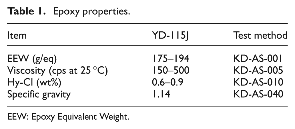
EEW: Epoxy Equivalent Weight.
In this study, instead of using a DP steel plate or boron steel, the specific strength and specific stiffness were increased by stacking the CFRP on the CR340, which has an excellent elongation rate. The thickness of the CR340 was 0.9 mm, and Table 2 lists the mechanical properties.
Properties of CR340.
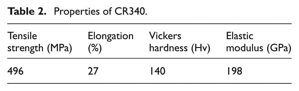
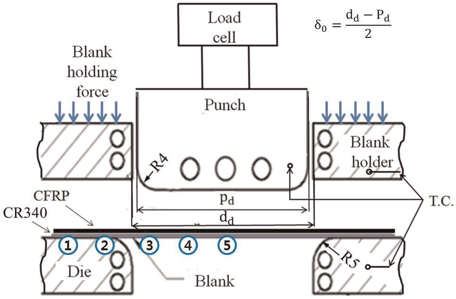
Figure 1 shows a brief diagram of the equipment used in the deep drawing experiment. Table 3 lists the detailed die dimensions for deep drawing. In the equipment, the load cells were attached to the punch and clamp. A cartridge heater was used to heat the punch, clamp, and lower die. At each die part, thermocouples were attached to maintain a temperature of 140 °C.
Experimental apparatus for deep drawing.
Dimensions for the deep drawing test (mm).
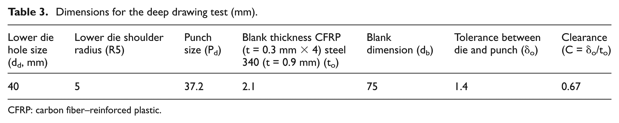
CFRP: carbon fiber–reinforced plastic.
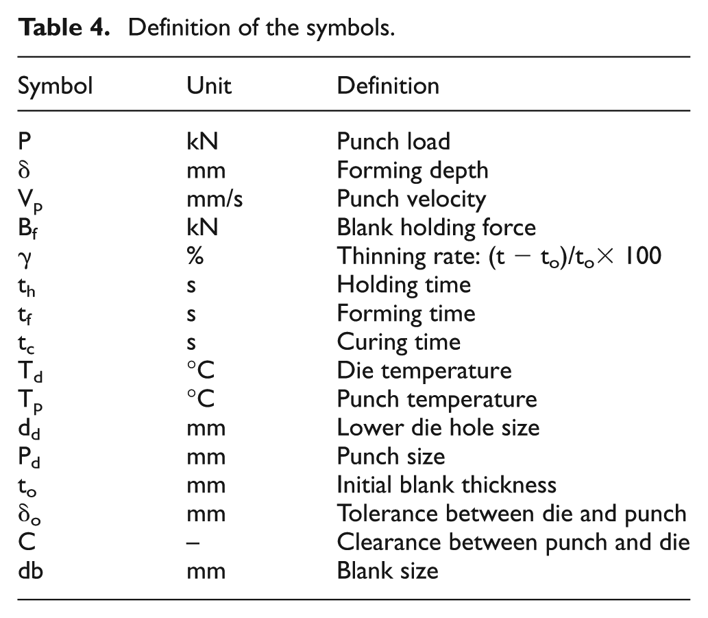
The diameter of the blank (db) was 75 mm. The thickness of CFRP was 0.3 mm, and four sheets of CFRP were stacked on a metal sheet whose thickness was 0.9 mm. Total thickness of CR340/CFRP composites was to 2.1 mm. During the deep drawing process, the gap between the punch and die (δo) was 1.4 mm and the clearance (C = δo/to) was set to 0.67 to compress toward side of CR340/CFRP. Table 4 lists the terms used in this experiment.
Definition of the symbols.
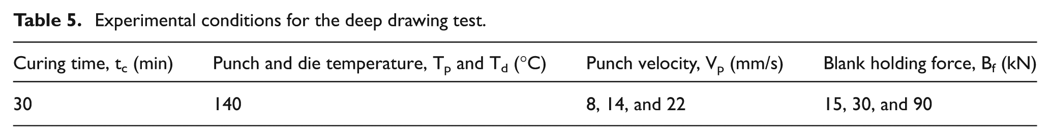
After heating the blank holder, punch and lower die with a cartridge heater until the temperature reached 140 °C, the blank for deep drawing was processed by controlling the blank holding force of the clamp and the punch velocity and after punch drew blank, punch pressurized for 30 min. Table 5 provides the detailed experimental conditions during the study. The deep drawing test was conducted for three specimens and the median value was reported in the graphs.
Experimental conditions for the deep drawing test.
The thickness changes at each position of the blank (nos 1–5) were measured from half of the prepared deep drawing cup, as shown in Figure 1, and the thickness changes were calculated using equation (1)
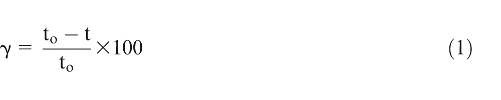
where γ, to, and t are the thickness reduction and specimen thicknesses before and after forming, respectively.
The epoxy flow was assessed by the thinning rate, and the problems at each position of the blank were examined using a digital microscope.
Experimental results and discussion
Temperature distribution as function of time
Figure 2 presents the temperature distribution at positions nos 1 and 2 of the deep drawing specimens as a function of time during forming. The initial temperature at positions nos 2 and 3 before forming was greater than that of no. 1 because these two points contacted the lower die, which was heated to 140 °C. Subsequently, although the clamp was lowered, the temperatures at positions nos 2 and 3 gradually increased by heat transfer. At the moment of clamp holding, as shown in Figure 2(b), the temperature at position no. 3 increased sharply. At position no. 2, the temperature gradient was increased over time due to the increased temperature transfer from position no. 3. Finally, during forming, when the punch, which was heated to 140 °C, touched position no. 1, the temperature at position no. 1 increased abruptly to more than 140 °C within 2 s of contact. An increase in temperature also occurred at position no. 2 between the punch and the side of the lower die. After 8 s of forming, the temperatures at all positions in the blank were increased to more than 140 °C.
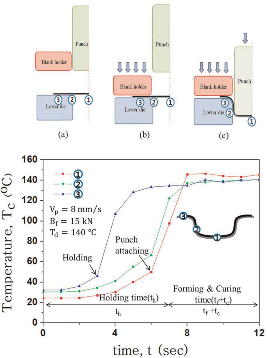
Temperature distribution according to heating time: (a) before forming, (b) holding, and (c) forming.
Relationship between load of CR340 and forming depth according to blank holding force and punch velocity
Figure 3(a)–(c) shows the results of the deep drawing test of CR340 according to the changes in Vp and Bf. As shown in Figure 3(a), when the blank holding forces were 15, 30, and 90 kN, the forming depths were 15, 10, and 6.5 mm, respectively. The forming depth decreased with increasing Bf.
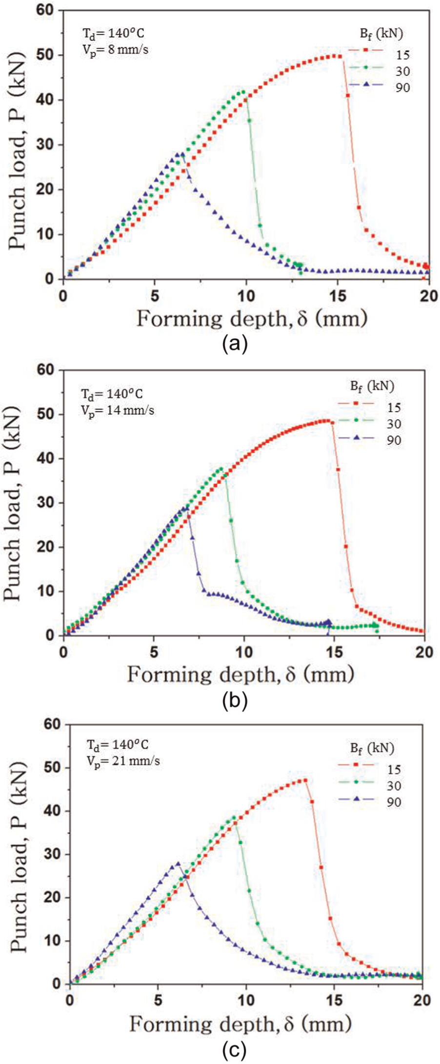
Relationship between punch load and forming depth (δ) according to Bf and Vp in deep drawing of 340 steel: (a) Vp = 8 mm/s, (b) Vp = 14 mm/s, and (c) Vp = 22 mm/s.
On the other hand, the forming depth of CR340 did not show any differences by the changes in Vp, as shown in Figure 3(a)–(c). During hot forming, the strain rate affects the punch load and forming depth. Note that the die temperature in this experiment was 140 °C. The forming depth did not change with Vp because this temperature is not high enough to affect the strain–stress curve of CR340. When Vp was 8 mm/s, the forming depth and punch load were 15 mm and 52 kN, respectively, whereas when Vp became 22 mm/s, the forming depth and punch load were 14.6 mm and 50 kN, respectively, which are not significantly different.
Relationship between load of CR340/CFRP composite and forming depth according to blank holding force and punch velocity
Figure 4(a)–(c) shows the deep drawing results for CR340/CFRP according to the changes in Vp and Bf. As shown in Figure 4(a), when Bf had values of 15, 30 and 90 kN, the forming depths decreased to 11.2, 10, and 8 mm, respectively. A comparison of Figures 2(a) and 3(a) shows that when Vp = 8 mm/s and Bf = 15 kN, the fracture load of CR340 is 50 kN and the fracture load of CR340/CFRP is approximately the same. However, when Bf ≥ 30 kN, the fracture load of CR340/CFRP is higher than the fracture load of CR340. This means that when Bf ≥ 30 kN, CFRP affects the fracture load. Two reasons for this phenomenon can be given. This might be because the blank holder pulled CFRP, which ultimately caused this material to stretch, resulting in an increase in punch load, when Bf was greater than 30 kN. In addition, the tolerance between the punch and die was 1.4 mm, whereas the thickness of the CR340 steel was 0.9 mm. Therefore, C (δo/to) became 1.6, and there was no friction between CR340 and the die wall surface. The thickness of the CR340/CFRP composite was 2.1 mm, and C (δo/to) was 0.7, which created friction between the die wall surface and the material during forming and caused increasing punch load. The ironing effect caused by friction might be one of the factors for the increase in the forming depth. As shown in Figure 3(a)–(c), the forming depth for CR340 was relatively insensitive to Vp. In contrast, the forming depth for the CR340/CFRP composite was affected by Vp, as indicated in Figure 4(a)–(c). In the CR340/CFRP composite, when Vp increased to 8, 14, and 22 mm/s, with Bf = 90 kN, the forming depths decreased to 8, 7.6, and 6.4 mm, respectively. Therefore, the strain rate was not affected by the changes in Vp, but CFRP was affected by Vp.
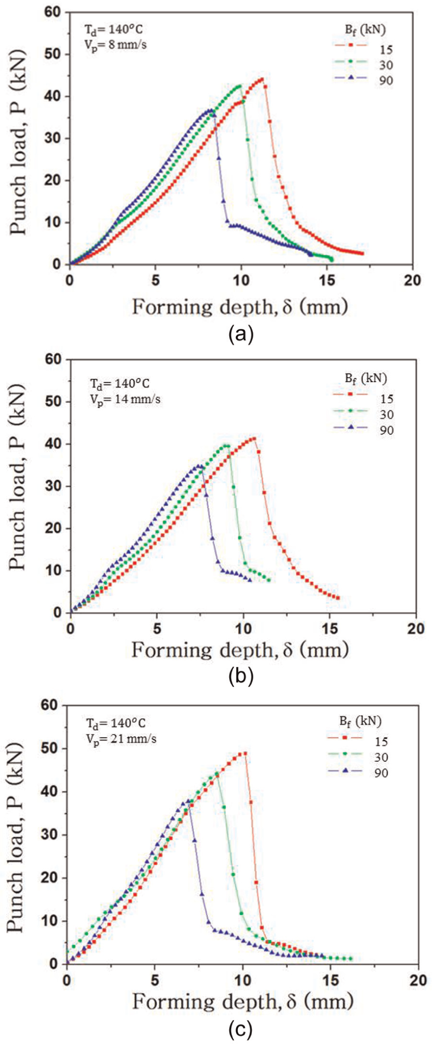
Relationship between punch load and forming depth (δ) according to Bf and Vp in deep drawing of 340 steel/CFRP hybrid composites: (a) Vp = 8 mm/s, (b) Vp = 14 mm/s, and (c) Vp = 22 mm/s.
Comparison of forming depth according to punch velocity and blank holding force
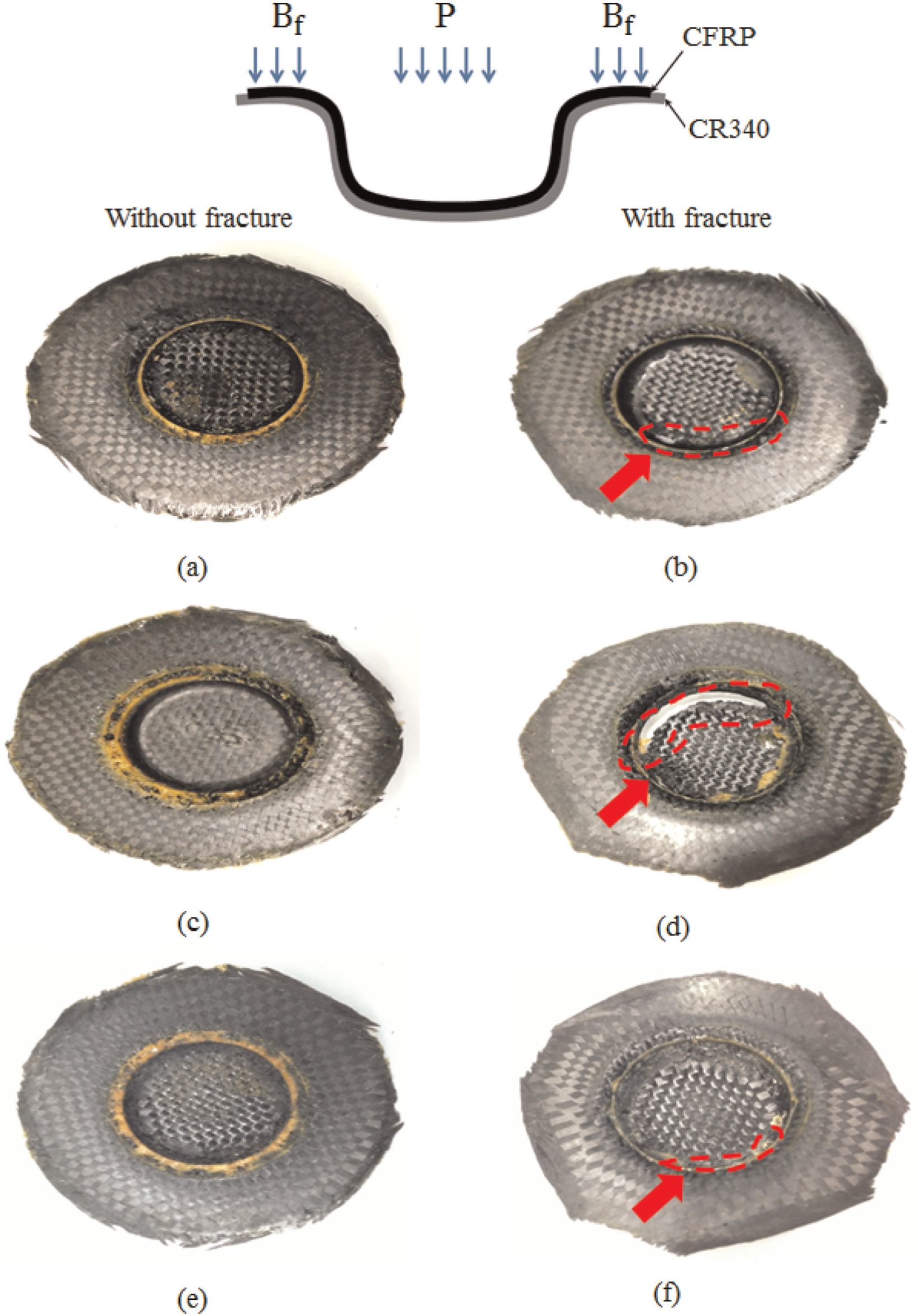
Figure 5 shows a cup-shaped specimen after the deep drawing of the CR340/CFRP composite according to the Bf changes when Vp = 8 mm/s. Figure 5(a), (c), and (e) confirms that no fracture occurred when the forming depths were 11, 10, and 7 mm, with increases in Bf to 15, 30, and 90 kN, respectively. On the other hand, with increases in Bf to 15, 30, and 90 kN, fracture occurred at 11.5, 10.5, and 8 mm, as shown in Figure 5(b), (d), and (f), respectively. From the fractured test specimens, fracture started from the R portion of the punch.
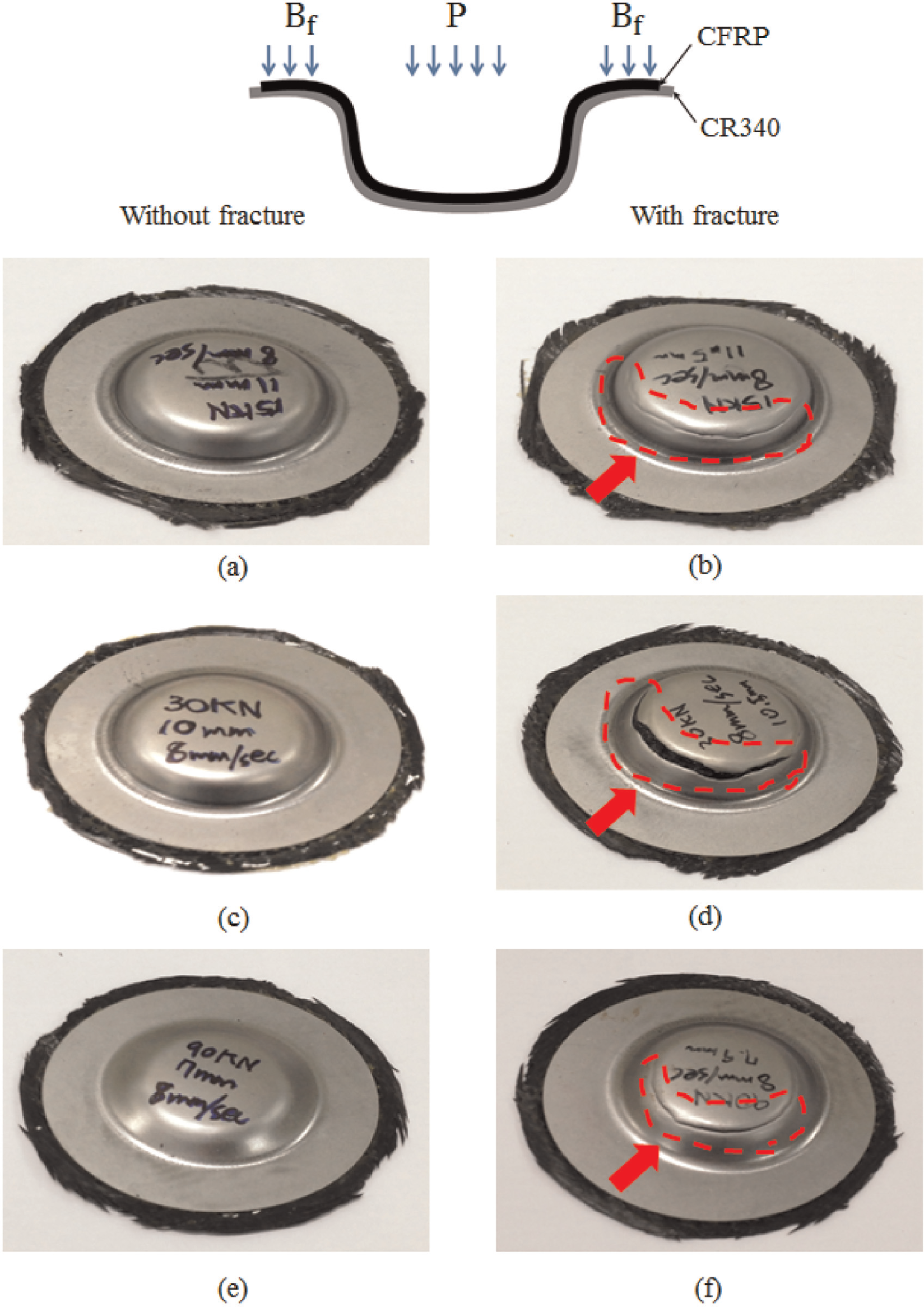
Upper side view of cups and forming depth (δ) after deep drawing according to Bf at Vp = 8 mm/s: (a) Bf = 15 kN, δ = 11 mm; (b) Bf = 15 kN, δ = 11.5 mm; (c) Bf = 30 kN, δ = 10 mm; (d) Bf = 30 kN, δ = 10.5 mm; (e) Bf = 90 kN, δ = 7 mm; and (f) Bf = 90 kN, δ = 8 mm.
Figure 6 presents an illustration of the safe region where fracture did not occur, the transition segment, and the unsafe region by setting the values of the forming depth where fracture occurred and without fracture as the boundary region when Vp = 8 mm/s. Both CR340 and the CR340/CFRP composite showed a decrease in forming depth with increasing Bf. When Bf was increased to 15, 30, and 90 kN, the forming depths of CR340 without fracture were 14, 8, and 5.1 mm, respectively, whereas the respective forming depths in the CR340/CFRP composite were 11, 10, and 7 mm. When Bf = 15 kN, the forming depth without causing fracture was 14 mm, which was higher than the forming depth of the CR340/CFRP composite (11 mm). In contrast, when Bf = 30 kN, the forming depth of the CR340/CFRP composite increased to 10 mm, whereas that of CR340 was only 8 mm. The forming depth at which fracture did not occur in CR340 was decreased prominently after Bf = 30 kN. On the other hand, the gradient of the forming depth decreased in the CR340/CFRP composite as the blank holding power was increased. When Bf > 30 kN, the safe region increased more in the CR340/CFRP composite than in CR340. This is because there was no friction between CR340 and the die wall surface because the tolerance between the punch (δo) and die was 1.4 mm, whereas the thickness of the CR340 steel was 0.9 mm. Therefore, C (δo/to) became 1.6. For the CR340/CFRP composite, its thickness was 2.1 mm and C was 0.7, which created friction between the die wall face and the material during forming. The ironing effect caused by friction might be one of the factors for the increase in the forming depth.
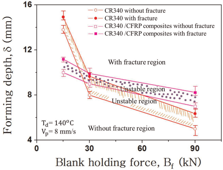
Relationship between forming depth (δ) and blank holding force (Bf) with Td = 140 °C and Vp = 8 mm/s.
Figure 7 shows the rear face of the cup shape after the deep drawing of the CR340/CFRP composite according to the changes in Vp and Bf. Because there is a gap between the R part of the die and the punch, a large quantity of epoxy flowed out of the die, and this epoxy flow increased at the R part of the die with increases in Bf to 10, 30, and 90 kN, as shown in Figure 7(a), (c), and (e). Figure 7(b), (d), and (f) shows the rear face of the specimens when fracture occurred with Bf = 30 kN and increased Vp. On those specimens, the amount of epoxy was lower than that on the non-fracture specimens at the R part of the die. Because fracture occurred at the R part of the punch and a large quantity of epoxy flowed out of the die, some epoxy flowed out through the R part of the punch, and this decreased when the fracture occurred. From the rear part of CFRP, the fiber alignment and directivity of the plain weaved CFRP were not changed significantly by increases in Bf, as shown in Figure 7(a), (c), and (e). On the other hand, with increases in Vp, the fiber directivity of CFRP became uneven. Therefore, the fiber was either elongated or showed alignment flowing toward the R portion of the die. The sagging or distortion in the alignment direction of the fiber might have also been caused by the epoxy contents and mechanical properties.
Bottom side view of cups and forming depth (δ) after deep drawing according to Bf and Vp: (a) Bf = 15 kN, Vp = 8 mm/s; (b) Bf = 30 kN, Vp = 8 mm/s; (c) Bf = 30 kN, Vp = 8 mm/s; (d) Bf = 30 kN, Vp = 14 mm/s; (e) Bf = 90 kN, Vp = 8 mm/s; and (f) Bf = 30 kN, Vp = 22 mm/s.
Figure 8 shows a diagram of the safe region where fracture did not occur, the transition segment, and the non-safe region where fracture occurred based on the forming depth within the boundary according to Vp when Bf was 90 kN. As shown in Figure 3(a)–(c), in CR340, the forming depth did not change significantly as the punch velocity was changed. On the other hand, the forming depth was gradually reduced in the CR340/CFRP composite as the punch velocity became faster. The alignment of CFRP was expected to be sensitive to the punch velocity, so that the fiber would become thin or elongated, which would affect its mechanical property, and consequently affect the forming depth. A comparison of CR340 and CR340/CFRP confirmed that when Bf = 90 kN, the CR340/CFRP composite had better formability and could be formed within a safer region.
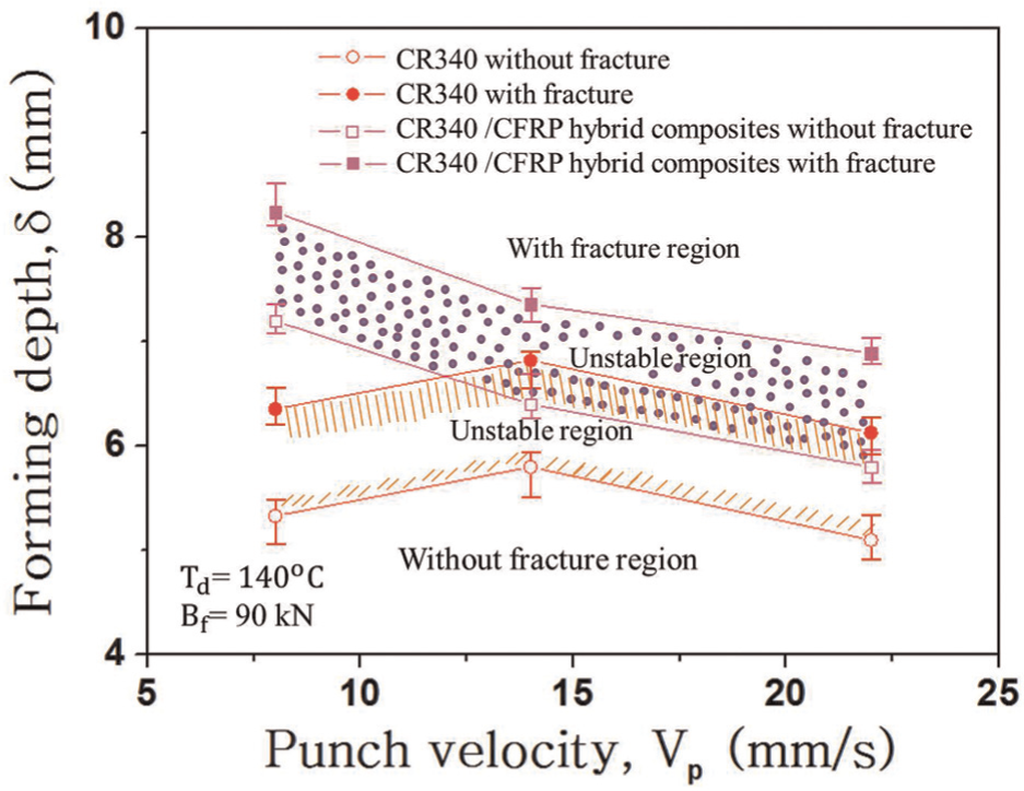
Relationship between forming depth (δ) and punch velocity (Vp) with Td = 140 °C and Bf = 0 kN.
Relationship between blank holding force and thinning rate of each position in CR340/CFRP composite
Figure 9 shows the thinning rate of the CR340/CFRP composite at each position (nos 1–5) when fracture did not occur according to the changes in Vp and Bf. The thinning rate is a percentage value of the thickness changes divided by the initial thickness. When the thickness decreases while the forming depth increases, the thinning rate increases as a positive value. In contrast, if the thickness is increased from the initial value, the thinning rate becomes a negative value. As shown in Figure 9(a), at position no. 1, where there is almost no change in thickness, similar thinning rates are observed regardless of the Bf values. On the other hand, at position no. 3, with decreasing Bf from 90, 30, and 15 kN, the forming depth was increased to 7, 10, and 11 mm, respectively, which made the workpiece thin with an increase in the thinning rate to 3.1%, 4.8%, and 7.6%, respectively. Similarly, the thinning rate decreased at position nos 4 and 5 with increasing Bf to 15, 30, and 90 kN. Similar phenomena are observed in Figure 9(c). However, a decrease in the thinning rate is observed at position no. 2 regardless of the Bf values. This might be due to irregular epoxy flow between the R position of the die and the punch at position no. 2.
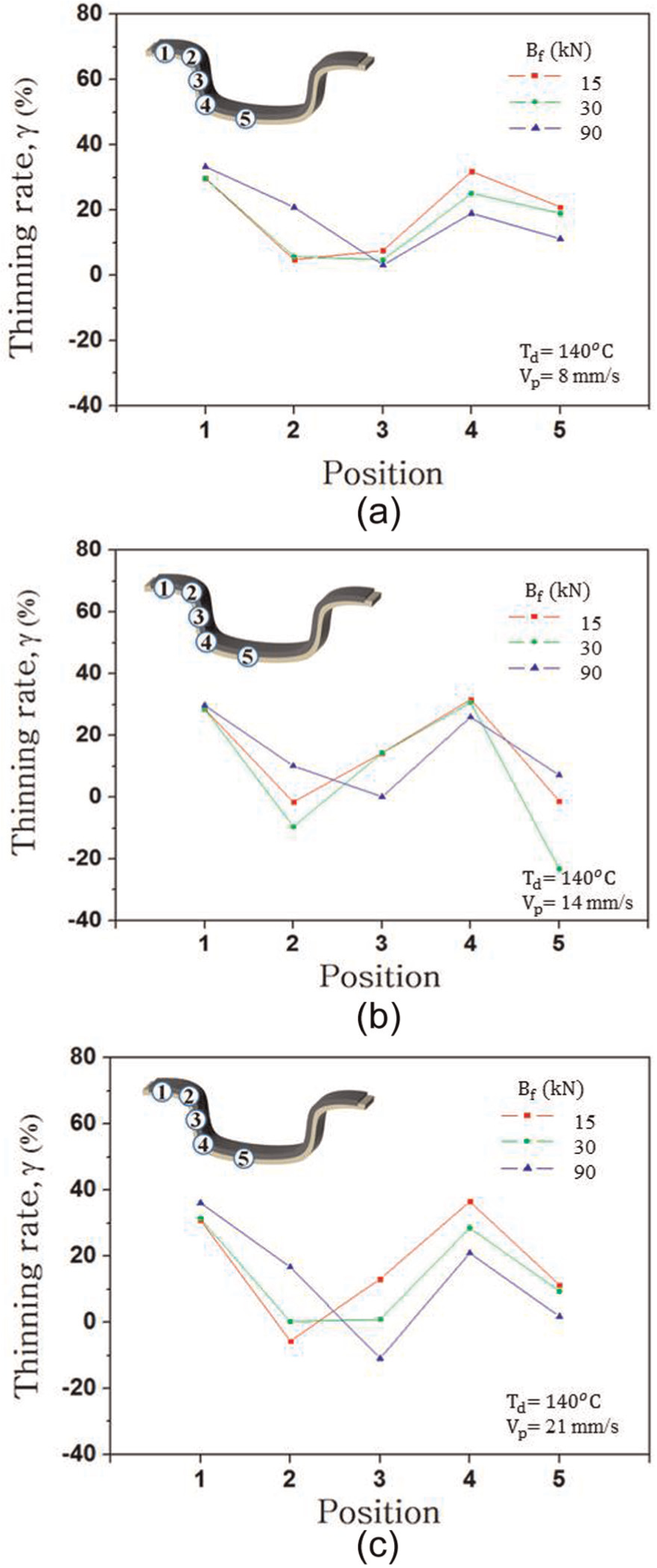
Thinning rate at each position according to blank holding force (Bf) and punch velocity (Vp) in sample without fracture: (a) Vp = 8 mm/s, (b) Vp = 14 mm/s, and (c) Vp = 22 mm/s.
Figure 10(a)–(c) shows the thinning rate of each position (nos 1–5) when fracture occurred in the CR340/CFRP composite according to the changes in Vp and Bf. Similar to an earlier phenomenon, the thinning rate was either similar or increased by increases in Bf at positions nos 3–5, as shown in Figure 10(a)–(c), respectively. The difference was not large because the forming depths were 11 and 10 mm when the CR340/CFRP composite was fractured when the values of Bf were 14 and 30 kN, respectively. Accordingly, either the thinning rate was similar or the forming depth was increased at some measurement positions when Bf = 30 kN.
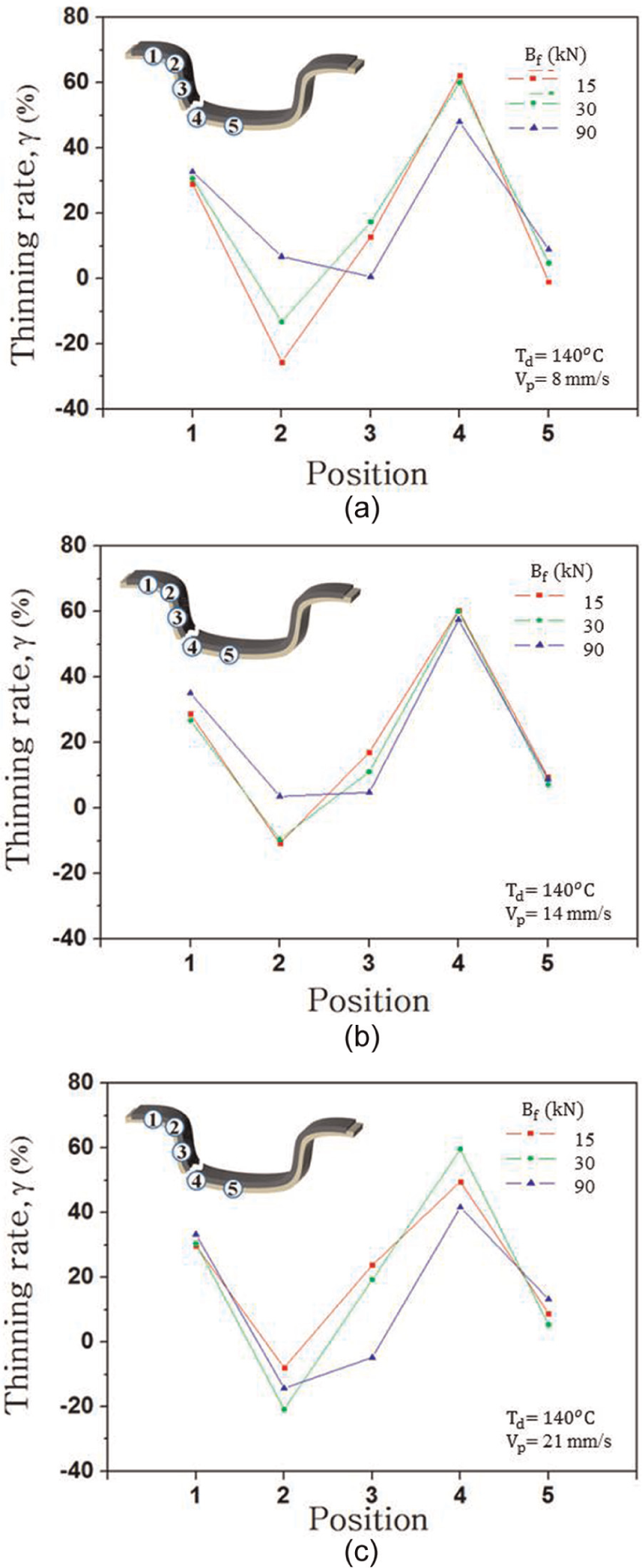
Thinning rate at each position according to blank holding force (Bf) and punch velocity (Vp) in sample with fracture: (a) Vp = 8 mm/s, (b) Vp = 14 mm/s, and (c) Vp = 22 mm/s.
Thinning rate according to punch velocity
Figure 11 shows the relationship between Vp and the thinning rate by categorizing the safe region where fracture did not occur, the transition region, and the non-safe region where fracture occurred, by setting the thinning rates where fracture occurred and fracture did not occur as the boundary region at position no. 4, which was the round part of the punch, when Bf = 90 kN. The thinning rate was relatively insensitive to Vp. Although CFRP was affected by Vp, in the case of the thinning rate, there was no change in thickness at position no. 4, which was the round part of the punch, because the thickness of CR340 was 0.9 mm. Although CFRP became very thin, it did not have a significant effect on the thinning rate. A thinning rate of 18% was observed at position no. 4, where the round part of the punch was contacted and fracture occurred. After fracture, a maximum thinning rate of approximately 60% was observed at the same position. The region where the thinning rate was in a range of 18%–60% was a transition segment and was unstable enough to create difficulty in recognizing the fracture. The region where the thinning rate was less than 18% was found to be safe from fracture.
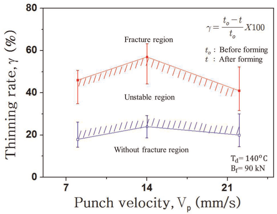
Relationship between thinning rate (γ) and punch velocity (Vp) with Td = 140 °C and Bf = 90 kN.
Problems in deep drawing of CR340/CFRP composite
Figure 12 shows the problems that occurred with the specimen in the fracture case, as well as the non-fracture case, for the steel 340/CFRP composite when Vp = 14 mm/s and Bf = 30 kN. In both cases, an interfacial delamination of CFRP and CR340 occurred at position no. 2, and the epoxy flowed out and cured around the round part of the die. When fracture occurred, epoxy could flow out through the fractured cleaves. However, when fracture did not occur, the epoxy could not escape; it leaked from the round part of the die at position no. 2. This interfacial delamination or epoxy leakage made it difficult to correctly measure the thickness at position no. 2. Therefore, the thinning rate trends were also different at position no. 2, as shown in Figures 7 and 8. The thickness significantly decreased at position no. 3, which was the middle position between the round part of the die and the round part of the punch. This might be because the clearance (C) during deep drawing was 0.67, which made the inflow of CR340 into the die easier. In contrast, the inflow into the die was relatively difficult in the case of CFRP, which led to a significant decrease in thickness at position no. 3. This suggests that the problem was due to a change in thickness, whereas the changes produced products with an even thickness. At position no. 4, where fracture occurred, curing began after fracture during the deep drawing process. Subsequently, the cured was completed after CR340 and CFRP had already separated. Therefore, the CFRP at the bottom of the punch could not be in contact with the material causing interfacial delamination and interlayer delamination in the product.
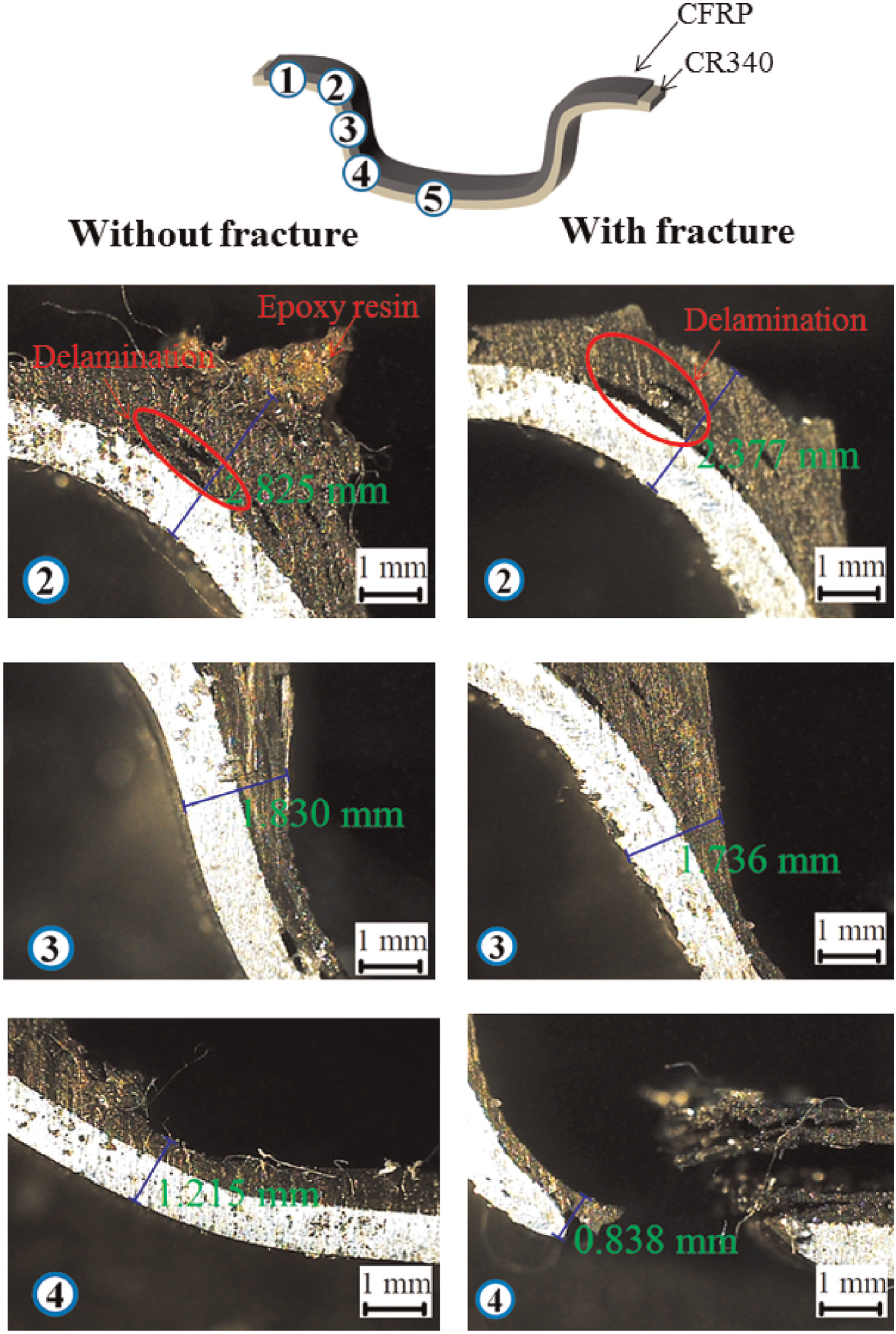
Problems for workpiece with fracture and without fracture after deep drawing.
Figure 13 shows the thickness distribution at each position of the blank when fracture did not occur, with Vp = 8 mm/s and Bf = 15 kN. The thickness of the initial CR340 was 0.9 mm, and the thickness was relatively constant, except for position no. 4, where fracture occurred. Thinning occurred because the thickness was 0.847 mm at the round part of the punch during forming. For the CFRP, the initial thickness of 1.2 mm was decreased due to the epoxy flowing toward the outside and the compression imposed on the fiber during the clamping and deep drawing. At position no. 1, the thickness was decreased to 0.552 mm by the compression. On the other hand, at position no. 2, the epoxy flowed but could not leak out from the die; it gathered at the side of the punch and the round part of the die and was ultimately cured, as shown in Figure 13. When epoxy gathered at this position, the thickness increased. No compression occurred at the round part of the die, which led to interfacial delamination. At position no. 3, which was located between the round part of the die and the round part of the punch, there was a sudden decrease in the thickness of the increased CFRP with an initial thickness of 0.838 mm. At position no. 4, which was the round part of the punch, the material was compressed by the round part of the punch immediately before fracture. Therefore, the CFRP thickness was the least at 0.303 mm. Position no. 5 was only compressed by the punch, and its thickness was similar to that of position no. 1, that is, 0.675 mm.
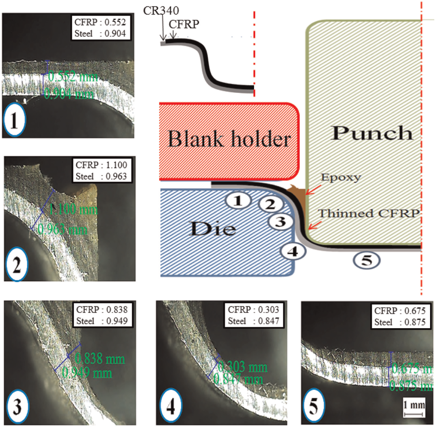
Thickness variation at each position after deep drawing with Bf = 15 kN and Vp = 8 mm/s.
Microstructure of CR340/CFRP composites
Figure 14 shows the microstructure of the CR340/CFRP composite with Vp = 8 mm/s and Bf = 15 kN. Because the punch and holder were pressurized, there was no porosity or only small pores (50–60 µm) at positions nos 1 and 5. At the round part of the die (position no. 2), pores with a size of 100–200 µm occurred between the CFRP layers, which were affected by these pores. For example, delamination problems occurred, as shown in Figure 12. The fiber thickness suddenly decreased at position no. 3 with an increase in the thinning rate for CFRP. The pore size was 20–30 µm. Position no. 4 was the round part of the punch. However, the results for this position were different from those for position no. 2, the round part of the die, and no delamination occurred. This was because the punch-pressurized inner part of the CFRP and CR340 loaded a reacting force on the outer part of the CFRP. The porosity was also suppressed, and only small pores appeared.
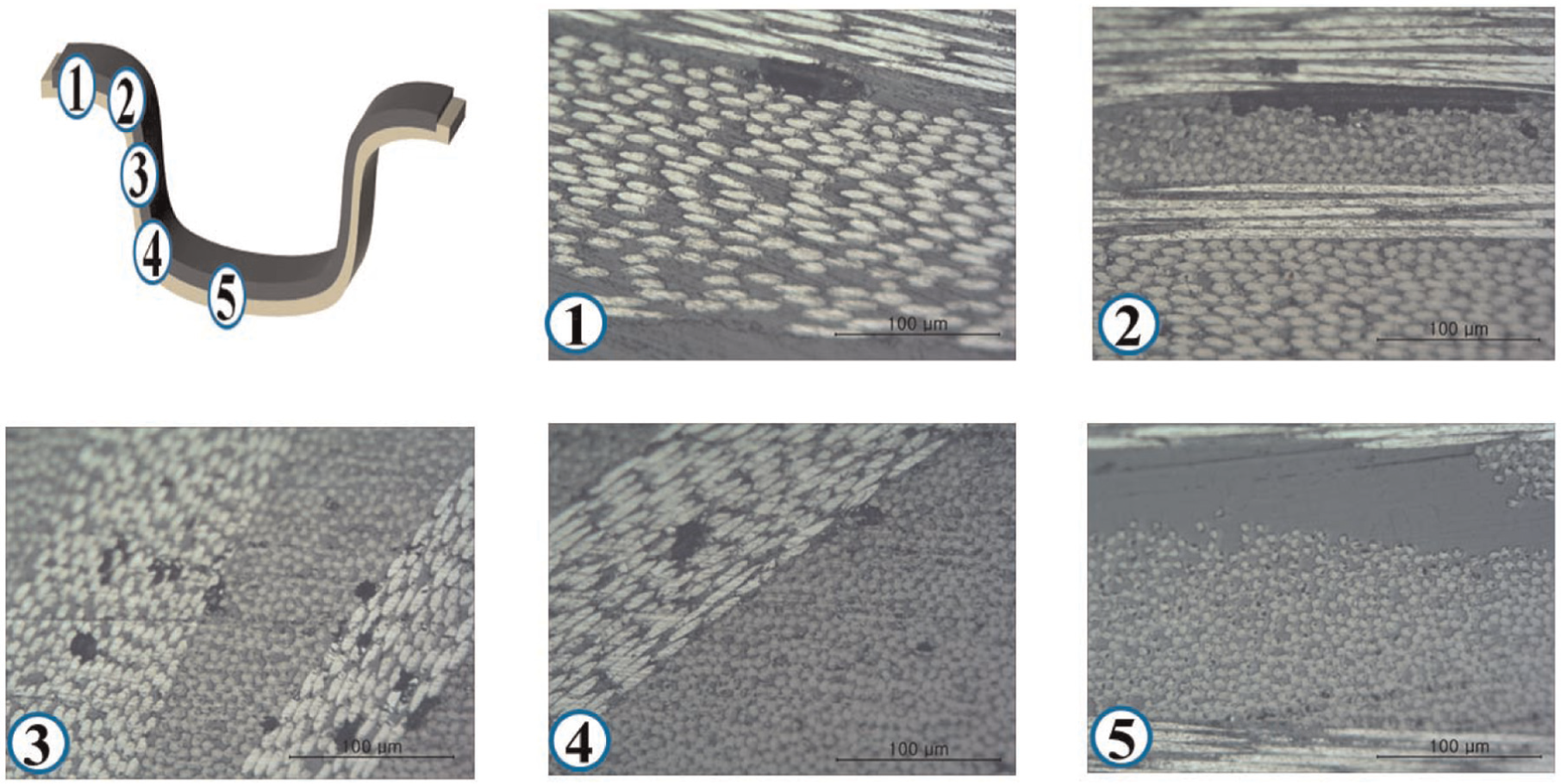
Microstructure of CR340/CFRP composites with Bf = 15 kN and Vp = 8 mm/s.
Figure 15 shows the microstructures of the CR340/CFRP composite at the round parts of the die and punch according to Bf, with Vp = 8 mm/s. As shown in Figure 15(a), when Bf = 15 kN, there are several 50 to 70 µm pores at the round part of the die. The mechanical properties and delamination were affected by these pores. As the blank holding force increases, the number and size of the pores decrease, as shown in Figure 15(a)–(c). When Bf = 90 kN, the porosity was small, and the size of the pores was also small (10–20 µm), as shown in Figure 15(c). Figure 15(d)–(f) shows that the number and size of the pores likewise decrease with an increase in the blank holding force at the round part of the punch (position no. 4). When Bf ≥ 30 kN, the porosity was practically nonexistent.
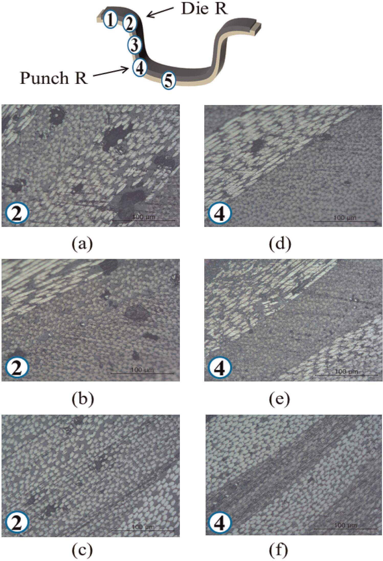
Microstructures of CR340/CFRP composites at round parts of die and punch according to blank holding force: (a) Bf = 15 kN, (b) Bf = 30 kN, (c) Bf = 90 kN, (d) Bf = 15 kN, (e) Bf = 30 kN, and (f) Bf = 90 kN.
Conclusion
In this study, the deep drawing process was performed to examine the forming property of a CR340/CFRP steel plate in relation to the changes in Bf and Vp. After the forming specimens were cut, the thinning rate at each position of the workpiece was measured, and the problems were discussed. The following results were obtained:
For Bf = 15 kN, because the friction by the holding force was lower, the forming depth of the CR340 plate was higher than the forming depth of CR340/CFRP. On the other hand, when the blank holding forces were increased to 30 and 90 kN, the forming depth of CR340/CFRP was higher than that of CR340 due to the ironing effect.
With changes in the punch velocity, the CR340 plate did not show a change in the forming depth, whereas the forming depth of CFRP decreased with increasing Vp. The fiber alignment also became uneven, causing it to either elongate or flow into the round part of the die. The mechanical properties could be affected by the punch velocity due to the fiber direction because CFRP is also an anisotropic material.
Overall, there were no uniform thickness distributions. In particular, for Bf = 90 kN at position no. 4, where compression from the round part of the punch was imposed. When the thinning rate was above 18%, the fracture at this position was observed. At position no. 3, the thinning rate was suddenly decreased.
At position no. 2 in the blank, interfacial delamination occurred from CFRP and CR340 at the round part of the die. Furthermore at this position, a large amount of epoxy leaked and cured at the round part of the die that increased by increasing the blank holding force. In addition, the porosity was suppressed with an increase in the blank holding force. The occurrence of a large porosity between layers affected the delamination.
Footnotes
Declaration of conflicting interests
The authors declare that there is no conflict of interest.
Funding
This study was supported by the Advanced Technology Center Project (10039031, The Development of the Manufacturing Process for the High Strength Steel and Composite Materials) funded by the Ministry of Knowledge Economy (MKE, Korea) and a National Research Foundation of Korea (NRF) grant funded by the Korea government (MSIP) through GCRC-SOP (no. 2011-0030013).