
Abstract
The variables of die temperature, pressure, time, lamination method, and forming count are applied to fabricate thermosoftening CFRP (CFRTP) with compression molding method. The mechanical properties of CFRTP are compared with those of thermosetting CFRP (CFRTS). The first lamination method is that one hotmelt is inserted into carbon fiber (five carbon fibers and four hotmelts). The optimal lamination conditions are the die temperature of 220°C, pressure of 6 MPa, and pressurization time for 10 min. The tensile strength of CFRTP of this lamination method is 400 MPa. For higher tensile strength value, the second lamination method was applied. CFRTP prepreg was prepared with one hotmelt and one carbon fiber by applying die temperature at optimal lamination conditions. Five CFRTP prepregs were laminated under the same conditions. When the CFRTP sheet was three formings, the tensile strength of 494 MPa could be obtained. CFRTS are prepared by laminating the epoxy prepregs at 140°C with the compressive pressure of 0.5 MPa for 30 min. CFRTP sheet has the lower tensile strength than CFRTS sheet by 223 MPa, but the flexural strength was higher by 61 MPa and by 1.0 J/cm2 for Charpy impact test.
Keywords
Introduction
Since carbon fiber reinforced plastic (CFRP) has high tensile strength and high stiffness, many researches are being conducted in industry and research fields. CFRP is mainly applied to the automobile and aerospace industries, and its use scope is gradually increasing.1–3
Generally, CFRP is a process of hardening epoxy resin on carbon fiber to make reinforced plastic. This CFRP is called thermo-setting plastic CFRTS. CFRTS has the advantages of high tensile strength and stiffness. However, it has a problem of very low elongation of less than 1%. In the case of structural parts such as bumper beams and center pillars of a vehicle, because dynamic toughness is an important characteristic, there is a limit that it is not compatible for these parts. In order to solve the weak dynamic toughness problem of CFRTS, research is being conducted on CFRTS/steel hybrid material, in which steel plate is bonded to CFRTS. However, the biggest problem with CFRTS is that once it is cured, it cannot be melted again and is not possible to repair cured CFRTS, if cracks occurred or fibers are broken. If the problem of non-repairable problem of CFRTS is not resolved, it can cause serious environmental problems when applied to the automobiles and aviation industry and into mass production.4–12
While, thermo-softening plastic (CFRTP) has the advantage of partial repair in the form of a patch when melted by reheating. Because of these advantages, some researches on CFRTP are underway.13,14 More and more ongoing researches on CFRTP are needed in the future. In the case of the thermo-softening resin, since the viscosity is considerably higher than that of the epoxy, it is not easily penetrated to the carbon fiber, which makes it very difficult to be produced in prepreg form. In addition, as shown in previous studies, the properties of CFRTP are significantly inferior than that of CFRTS. Researches on thermo-softening might have not been that active due to these problems.15–17
Although CFRTP has lower mechanical properties than CFRTS, if the optimal process conditions for manufacturing CFRTP are in place and the mechanical properties comparable to CFRTS are maintained, it will play a good role in improving repairing, maintaining, and environmental problems. In addition, parts that do not require large mechanical properties can be replaced by CFRTP.
In this study, compression molding method and high viscosity hotmelt resin were used to prepare CFRTP. In order to improve the mechanical properties of CFRTP to maximum level, experiments were conducted to find the optimum conditions using variables such as die temperature, pressure, forming time, lamination method, and pressurization count. The prepared CFRTP was subjected to a tensile test to select the optimal lamination conditions from the tensile strength value. In addition, CFRTS was prepared in the same laboratory environment by applying the optimal lamination conditions of thermosetting plastics (CFRTS) proposed by Lee and Kang 18 Tensile test, three-point bending test, and Charpy impact test were performed on these two types of CFRP, and the test results were compared and analyzed.
Fabrication of CFRTP sheet
Experiment method
Raw material preparation
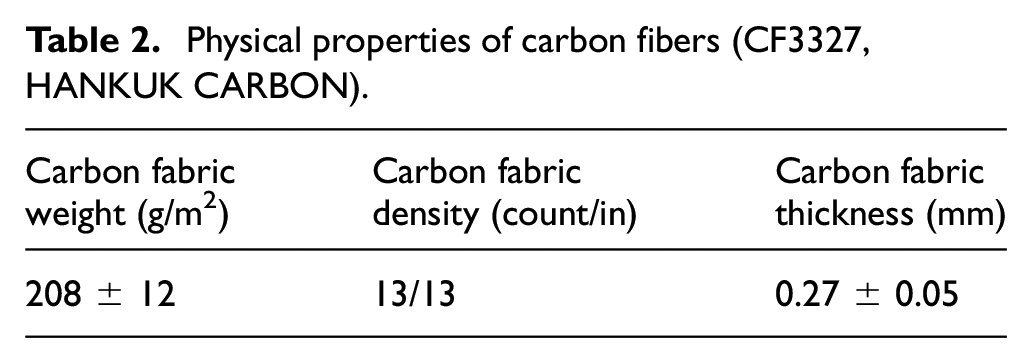
A carbon fiber and a thermoplastic resin hotmelt were prepared to manufacture CFRTP sheet. hotmelt used in study is adhesive copolymer film of SHINKWANG Co., Ltd. It is a solid and modified polyolefin. Hotmelt is in the form of a film and thickness is 0.25 mm. Density of hotmelt is 1.07 g/cm3 and Molecular Weight of Repeat unit is 113 g/mol. Content of hotmelt resign 48%–50%. Carbon fiber used in the study was obtained from the HANKUK CARBON Co., Ltd. The type of fabric corresponded to a plain weave. The thickness of the carbon fibers is 0.27 mm. The properties of hotmelt and carbon fiber are shown in Table 1 and Table 2, respectively.
Physical properties of hotmelt (NHC-1000, SHINKWANG HOTMELT).

Physical properties of carbon fibers (CF3327, HANKUK CARBON).
Hotmelt and carbon fiber were cut into sheets as shown in Figure 1. Hotmelt width and height are 150 and 110 mm, respectively, and carbon fiber width and height are 220 and 180 mm, respectively. Hotmelt was prepared with varied sizes and then laminated with the carbon fiber. When the size of hotmelt film was small, it was not evenly laminated into the carbon fiber, while when the hotmelt size was big, the resin was flown out from the die. When the size of the hotmelt resin was 50 mm × 110 mm, the resin did not overflow from the mold and it could be bonded well with the carbon fiber (220 mm × 180 mm).

Preparation of raw material: (a) hotmelt film, and (b) carbon fiber.
Lamination
Compression molding method was applied to prepare the CFRTP sheet. The variables of forming time, temperature, pressure, lamination method, and pressurization count were applied to find out the optimal lamination conditions for the compression molding method. Table 3 shows the conditions of variables in the lamination test for CFRTP. When the hotmelt is placed on the carbon fiber and this hotmelt-carbon fiber layer is pressurized for a long duration, the two sheets would push each other. Considering this phenomenon, the pressurization duration was set as the first variable. Because hotmelt is easily get strained and its properties are changed under different temperatures, the temperature was set as the second variable. While, the thickness of sheet and amount of air pore are affected by the pressure, the pressure was set as the third variable.
Lamination conditions of CFRTP.
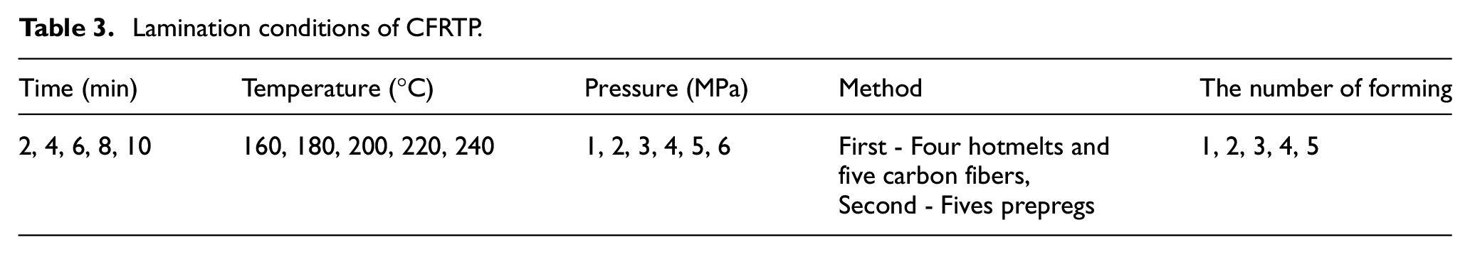
The lamination method was chosen as the fourth variable. The lamination method wherein the hotmelt sheet was inserted into the carbon fiber (a total of five sheets of carbon fiber and four sheets of hotmelt) as shown in Figure 2(a) was designated as the first lamination method. As the second lamination method, one sheet of the hotmelt was placed on the one sheet of carbon fiber as shown in Figure 2(b) and then this stack was pressurized to make a prepreg. Five sheets of so prepared prepregs were laminated. After finding the first lamination method, the optimal lamination condition for the time, temperature, and pressure was investigated. The obtained optimal lamination condition was applied on the second lamination method and so on. The pressurization count was set as the fifth variable and was applied only on the second lamination method.

Fabrication method of CFRTP sheet: (a) four hotmelts and five carbon fibers, and (b) five hotmelt prepregs.
Tensile test
The tensile specimens were processed from the CFRTP prepared by applying various variables to conduct tensile test. From the obtained tensile strength value, the optimal lamination condition for the variables was decided. The specimens were prepared in accordance with the ASTM D 3039. 19 The length and width of the deformed specimen were 105 and 32 mm, respectively. For the tensile test, a 25 t MTS was used, and cross head speed was set at 2 mm/min. The schematic diagram of processing the tensile specimen from the CFRTP sheet, and the prepared tensile specimens are presented in Figure 3. CFRP is a completely brittle material and it would be fractured the moment when yield is occurred. Therefore, its yield strength, tensile strength, and fracture strength all are the same, and in its stress and strain curve, only elastic zone (straight line) is presented.
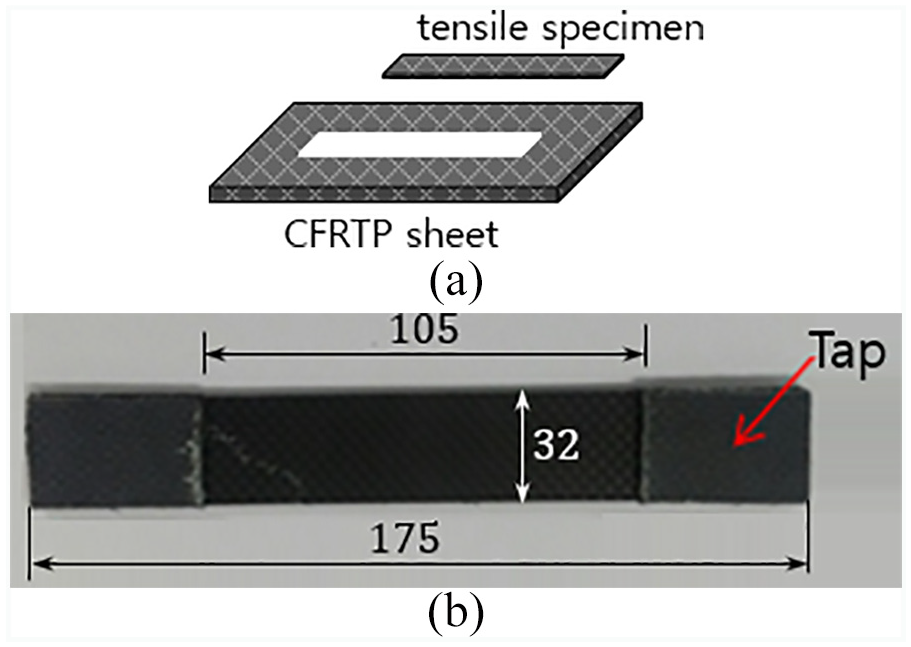
Preparation of tensile specimen: (a) cutting of tensile specimen from CFRTP sheet, and (b) true tensile specimen.
Microstructure analysis
The microstructures from the cross-section of the CFRTP sheet prepared with the first and the second lamination methods were examined using a digital microscope. First, the CFRTP sheet was cut in the width direction, and the cut section was polished using a polishing pad for microstructural study.
Experiment results
Tensile strength by time
When the hotmelt and carbon fiber were laminated by applying the first lamination method during compression molding, if the forming time became longer than 10 min, the two sheets pushed each other. The same phenomenon was not occurred when the forming time was shorter than 10 min. Since lamination is not possible if the two sheets push each other, the forming time for longer than 10 min was not applied as a variable. Figure 4 shows the tensile strength of the CFRTP with the different forming time for the lamination under the condition of die temperature at 140°C and pressure at 0.5 MPa. The stress and displacement curves show that displacement values in the five curves are varied. These values are not actual strain but are generated while the clamped portion of the tensile specimen in the tensile test jig is slipped. Therefore, tensile strength value is meaningful rather than interpreting the results in terms of strain. As the forming time become increases, the tensile strength generally increases. In this study, when the specimen was pressurized for 2 min, the resulting tensile strength was about 71 MPa, and with 4 min of forming time, it was about 80 MPa. The forming time of 6 and 8 min yielded the tensile strengths of 102 and 111 MPa, respectively. The forming time for 10 min, when the two sheets no longer pushed each other, the tensile strength value was the maximum of 143 MPa. The thickness at each point of the sample prepared with the forming time of 10 min was also the most uniform. The average thickness of the samples under this condition was 2.01 mm.

Stress versus displacement curve of CFRTP by forming time.
Tensile strength by temperature of die
During the lamination experiment by the forming time for 10 min, the maximum tensile strength value of 143 MPa could be obtained. Therefore, in the lamination experiment by the temperature, the forming time for 10 min and pressure at 0.5 MPa were set as fixed variables. Figure 5 shows the tensile strength of the CFRTP according the die temperature with the pressure 0.5 MPa and forming time for 10 min. As the die temperature was increased, the tensile strength value was also increased. However, the tensile strength value was decreased at the temperature higher than 220°C. When the temperature was at 220°C, the tensile strength was at maximum level of 283 MPa. The average thickness of the specimen under this condition was 1.80 mm and was uniform compared with those under other conditions. Whereas, the tensile strength at temperature 240°C was about 276 MPa, and thickness was also varied depending on the position. It might be due to viscosity changes of the hotmelt at higher than 220°C. The tensile strength value under the die temperature at 140°C was 143 MPa as shown in Figure 4. The different tensile strength value of 212 MPa at 160°C and 235 MPa at 180°C can be found from Figure 5. The difference of tensile strength at 140°C and 160°C was 69 MPa, while the difference of tensile strength at 160°C and 180°C was 23 MPa. The results indicate that though the melting temperature of the hot melt is 127°C, the hot melt can be well penetrated into carbon fibers under the temperature range of 160°C–220°C.

Stress versus displacement curve of CFRTP by die temperature.
Tensile strength by pressure
The maximum tensile strength value was obtained with the forming time for 10 min and die temperature at 220°C. Therefore, the fixed variables according to the pressurization condition were set as the forming time for 10 min and die temperature at 220°C. Figure 6 shows the tensile strength of the CFRTP by the pressure with the die temperature at 220°C and forming time for 10 min. As the pressure on the hotmelt and carbon fiber was increased, the tensile strength was also increased. That is, when the pressure was 1 MPa, tensile strength was 286 MPa, while the pressure was 2 MPa, the tensile strength of the specimen was 338 MPa. Similarly, when the pressure of 3 MPa was applied, the tensile strength of 380 MPa was obtained. Whereas, when the pressures of 4 and 5 MPa were applied, the obtained tensile strengths were 390 and 395 MPa, respectively. Further, when the pressure was at 6 MPa, the maximum tensile strength of 400 MPa could be obtained. The above results indicate that the tensile strength value was greatly increased as the pressure increases under the condition of the pressure at 3 MPa or lower. When the pressure was increased from 1 to 2 MPa, the tensile strength value was increased by 52 MPa, and when the pressure increased from 2 to 3 MPa, the tensile strength was increased by 42 MPa. However, under the pressurization condition of higher than 3 MPa, the increment of the tensile strength according to increases of the pressure was small. Again, while the pressure increased from 3 to 4 MPa, the tensile strength was increased by 10 MPa, and under the pressure condition higher than 4 MPa, the tensile strength was increased about 5 MPa with the increment of pressure by 1 MPa. Furthermore, when the lamination experiment was conducted with the pressure of higher than 6 MPa, the tensile strength value was far lower than that under the pressure of 6 MPa. Therefore, the tensile strength values under the pressure of higher than 6 MPa were excluded from the graph. The above results indicate that the hotmelt might be well penetrated into the carbon fibers only when the pressurization on the hotmelt and the carbon fiber becomes 3 MPa or more. Furthermore, under the pressure higher than 6 MPa, the hotmelt might have been flown out due to the high pressure after the hotmelt was penetrated to the carbon fiber. The average thickness of the CFRTP sheet with the pressure condition of 6 MPa is 1.40 mm.

Stress versus displacement curve of CFRTP by pressure.
Strength by lamination method and the number of formings
The first lamination method in Figure 2(a) shows that one sheet of the hotmelt is inserted between the carbon fibers (four sheets of hotmelt and five sheets of carbon fibers). The optimal lamination conditions derived from this lamination method are the die temperature of 220°C, pressure of 6 MPa, and forming time for 10 min. When the optimal lamination condition was applied with the first lamination method, the tensile strength of the CFRTP was 400 MPa. In order to derive higher tensile strength value, the second lamination method as in Figure 2(b) was applied. During applying the second lamination method, one sheet of the hotmelt and one sheet of the carbon fiber were used to prepare the prepreg, and then five sheets of this prepreg were laminated. The optimal lamination condition (pressure at 6 MPa, temperature at 220°C, forming time for 10 min) was adopted for both the cases of preparing one sheet of the prepreg and five sheets of prepreg. In addition, re-forming was conducted with the same lamination condition on the prepared CFRTP in order to take advantages of re-forming property of the thermo-softening CFRP.
Figure 7 shows the tensile strengths of CFRTP according to the lamination method. With the second lamination method and one-time forming, the tensile strength of 425 MPa was obtained which was higher by 25 MPa than that with the first lamination method. It can be concluded that the second lamination method is more effective in preparing the CFRTP than the first method. The re-formed CFRTP sheet prepared with the second lamination method could yield far higher tensile strength value. When the CFRTP sheet was pressurized once more (two formings), the tensile strength was 445 MPa, and with the forming one more time (three formings), the tensile strength of 494 MPa could be obtained. However, when the CFRTP sheet was pressurized more than three times, the tensile strength value was decreased. With the additional three times of forming, the tensile strength was 491 MPa, and the forming for additional four times resulted in remarkable drop of the tensile strength of 450 MPa. This gave ideas of the optimal pressurization condition for lamination of the CFRTP prepared with the second lamination method and pressurized for two times more (forming a total of three times). The average thickness of the CFRTP sheet laminated under this condition is 1.15 mm.

Tensile strength of CFRTP by lamination method.
Microstructures by lamination method and the number of formings
Figure 8 shows the microstructures of the CFRTP prepared with the first lamination method and the second lamination method. In Figure 8(a) shows the photo of microstructure of the CFRTP prepared with the first lamination method. There are some areas where the hotmelt was not penetrated to the carbon fibers and the area is large (red circles). Figure 8(b) shows the microstructure of the CFRTP prepared by with the second lamination method. There are some areas where the hotmelt was not penetrated at the boundary wherein direction of the carbon fiber is changed and other areas. However, with the increases of the pressurization count, the areas of hotmelt not penetrated decreases. Particularly, the microstructures with the second lamination method, the area where hot melt was not penetrated to the carbon fiber becomes relatively smaller as compared with that with the first lamination method. From the microstructural study, it could be concluded that the best combination for carbon fiber and hotmelt impregnation would be the forming trice with the second lamination method.

Microstructures of the CFRTP by lamination method: (a) first lamination method – Four hotmelts and five carbon fibers, and (b) second lamination method – five hotmelt prepregs.
Comparison of mechanical properties between CFRTP and CFRTS
Experiment method
Preparation of CFRTP and CFRTS
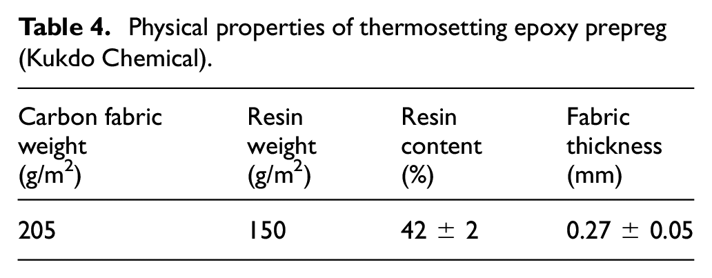
The CFRTP sheet as well as CFRTS sheet were prepared to compare the properties of the CFRTP and CFRTS according to the experimental conditions to achieve their desired properties. To the CFRTP, the optimal conditions found from the previous lamination experiment was applied. That is, the prepreg was prepared with the second lamination method (one sheet of hotmelt and one sheet of carbon fiber are made into prepregs, and these prepregs are overlapped), forming time for 10 min, pressure at 6 MPa, and temperature at 220°C, and then after forming once, two times of forming were executed. For preparing the CFRTS, the optimal condition suggested by Lee and Kang 18 was applied. The condition by Lee is that the epoxy prepregs are laminated with the compression molding method at 140°C, pressure at 0.5 MPa, and forming time for 30 min. The present experiment was conducted strictly under the same condition to prepare the CFRTS under the same laboratory environment with the study by Lee. Epoxy prepreg used for the experiment is the one from the Kukdo Chemical Co. Ltd, the same type used by Lee. The thickness of the epoxy prepreg is 0.25 mm. The resin content of the epoxy prepreg is 42%. The physical properties of thermosetting epoxy prepreg are shown in Table 4. The epoxy prepreg was cut 220 mm in width, and 180 mm in height for the lamination experiment. Curing temperature is 140°C–150°C.
Physical properties of thermosetting epoxy prepreg (Kukdo Chemical).
Tensile test
Five sheets of the hotmelt prepreg were laminated on the CFRTP sheet and five epoxy prepreg sheets were also laminated on the CFRTS. The thickness of the CFRTP sheet was 1.15 mm, while the thickness of the CFRTS sheet was 1.06 mm. The tensile specimens were then prepared from each of the prepared sheet. The tensile test method as described above was conducted for the two types of specimens.
Three-point bending test
When CFRTP sheet is under bending test, there is a problem of bending not performed due to elongation. Therefore, specimen of bending test was prepared thicker and wider. For the CFRTP sheet, 15 sheets of hotmelt prepregs are laminated. For the CFRTS sheets, 15 sheets of epoxy prepregs are laminated. Thickness of the CFRTP is 3.46 mm, thickness of the CFRTS is 3.15 mm. Figure 9(a) shows the prepared three-point bending test specimen. The bending test specimens were prepared from the CFRTP sheet and CFRTS sheet. The specimens were prepared in accordance with the ASTM D7264. 20 The length and width of the specimens of the bending test are 135 mm and 50 mm, respectively. Figure 9(b) shows the three-bending test specimen prepared from the CFRTP sheet and CFRTS sheet. Figure 9(a) shows method of the three-point bending test using the prepared test specimens. In case of the three-point bending test for composite materials, the ratio of both support point lengths (L) to the thickness (t) of the specimen is recommended as 32:1. 20 Since the thickness of the CFRTP and CFRTS specimen are 3.46 and 3.15 mm, respectively, the support point lengths of the CFRTP and CFRTS specimen are set at 110.7 and 100.8 mm, respectively. From the three-point bending test, a flexural strength value is obtained. Here, the flexural strength means a stress value at the outer side of the specimen from the occurrence point of maximum bending moment. At the load point, a maximum bending moment (0.25PL) is occurred. In addition, a flexural strength is occurred at the outer surface of the specimen. Equation (1) is for the maximum bending stress generated at the center in the longitudinal direction and at the outer surface of the cross section of the specimen.

Where, I is the 2nd moments of inertia, M is the maximum bending moment, c is the distance from the centroid to the outer surface of the specimen, L is the length of the support point, b is the width of the specimen, t is the thickness of the specimen, and P is the load.
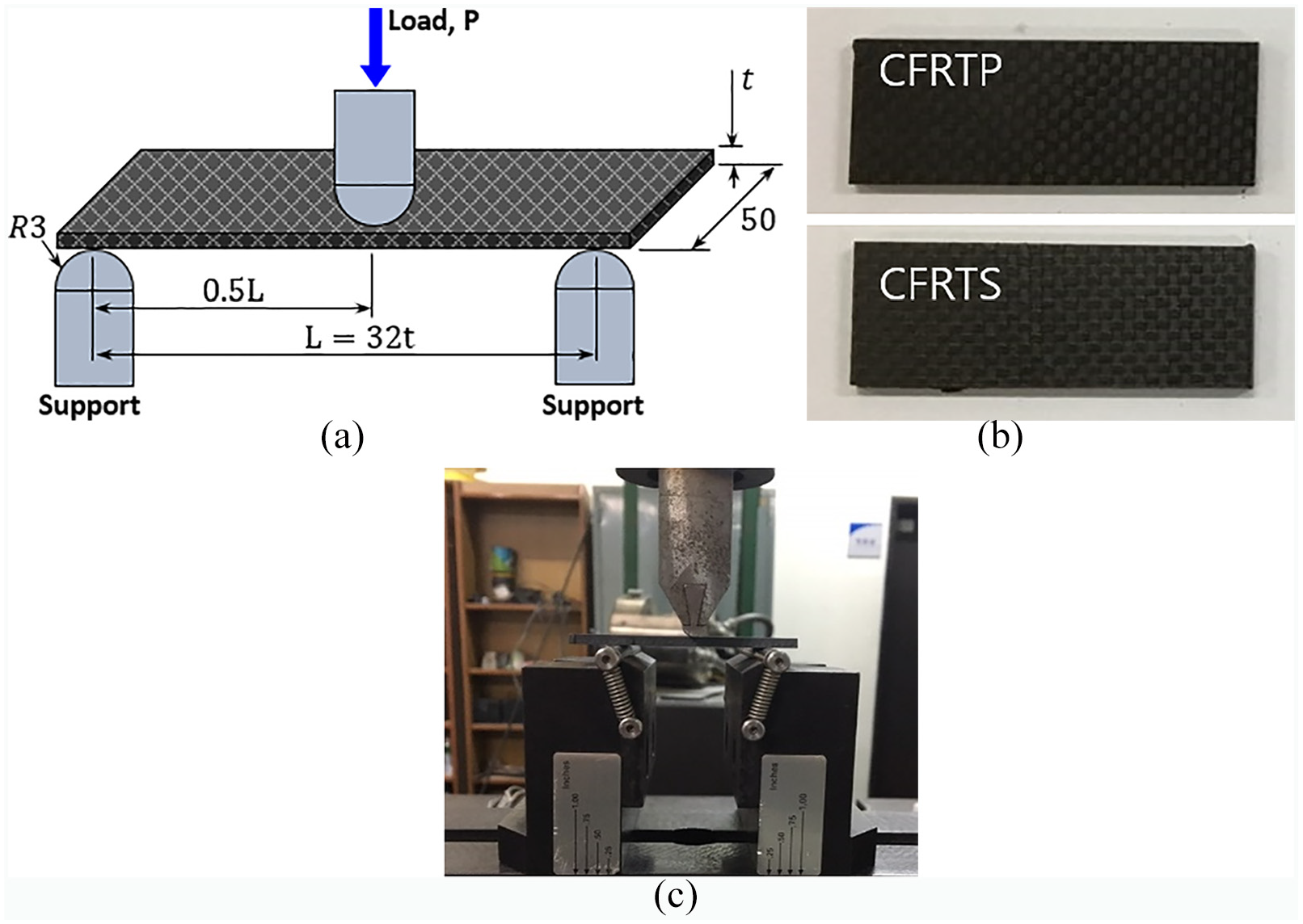
Specimen and equipment for three-point bending test: (a) test method (b) true specimens, and (c) true equipment.
Figure 9(c) shows the three-point bending tester and bending specimen used in this study.
Charpy impact test
The Charpy impact test was carried out to measure the dynamic toughness of the CFRTP sheet. There is no standard Charpy impact test method clearly provided for the composite materials. Therefore, the test specimens were prepared with the standard size from ASTM E 23. 21 ‘Standard size for the general metals.’ The preparation methods for the impact test specimen is presented in Figure 10. The standard thickness of the impact test specimen in the ASTM E23 is 10 mm. Therefore, steel plates were bonded at both sides to prepare the impact test specimen having thickness of 10 mm. Five hotmelt prepregs were laminated on the CFRTP to make its thickness 1.15 mm (t1). While, five epoxy prepreg sheets were laminated on the CFRTS to make its thickness 1.06 mm (t1). To the impact test specimen of the CFRTP, the steel plates with thickness 6 mm was boned onto the upper side, 2.85 mm (t2) onto the lower side. While, for the impact test specimen of the CFRTS, the steel plate having thickness of 6 mm was bonded onto the upper side, thickness of 2.94 mm (t2) onto the lower side. It should be noted that though the thicknesses of the CFRTP and CFRTS impact test specimens was the same at 10 mm, the thickness of only CFRTP is thicker by 0.09 mm than that of the CFRTS. Charpy impact test for sandwich CFRP between steel and only CFRP were performed, respectively.

Specimens of Charpy impact test: (a) dimension, and (b) true specimens.
Experiment results
Microstructures
Figure 11 shows the photos of the microstructure of cross-sectional direction of the CFRTP and CFRTS. In case of the CFRTP, some voids were found at the boundary (interface) where the direction of the carbon fiber is changed and in other areas. The amount of void was less in the CFRTS than CFRTP. The reason why the CFRTS has less void than CFRTP might be because the hotmelt prepreg was prepared in the laboratory, but epoxy prepreg was from the industrial source.

Microstructures of the CFRTP and CFRTS: (a) CFRTP and (b) CFRTS.
Tensile strength
Figure 12 shows the stress and displacement curves of the CFRTP and CFRTS obtained from the tensile test. The average tensile strength of the CFRTS is 718 MPa, and average tensile strength of the CFRTP is 495 MPa. CFRTS sheet exhibited higher tensile strength value than the CFRTP sheet by 223 MPa. This difference in the tensile strength between the thermosetting resin epoxy and thermoplastic hotmelt might be attributed by the difference in the mechanical properties between two materials. The results obtained from the experiment are due to displacement while the clamped portion of the tensile specimen in the tensile jig was slipped. Therefore, there is no meaning in the displacement values in the two graphs, and only the strength value on the breakage would be meaningful. Since the cut area of the tensile test specimen for CFRTP was 36.8 mm2, the specimen was fractured at the tensile strength of 18.2 kN, while when the cut area of CFRTS was 33.9 mm2, fracture occurred at 24.3 kN.

Stress versus displacement curve obtained from tensile test for CFRTP and CFRTS.
Flexural strength
Since the specimen thickness of CFRTP and CFRTS are 3.46 and 3.15 mm, respectively, the centroid (center of the cross section) of the cross section are 1.730 and 1.575 mm from the base surface, respectively. Therefore, compressive stress is generated from the centroid to the upper surface, and tensile stress is generated from the centroid to the upper surface. Because the stress value increases as the distance from the centroid increases, the maximum compressive stress occurs at the upper surface and the maximum tensile stress at the lower surface. Figure 13 shows the bending stress and displacement curves of the CFRTP and CFRTS obtained from the three-point bending test. The average flexural strength of the CFRTP is 812 MPa, and it was 751 MPa for the CFRTS. CFRTP sheet shows higher flexural strength than CFRTS sheet by 61 MPa.
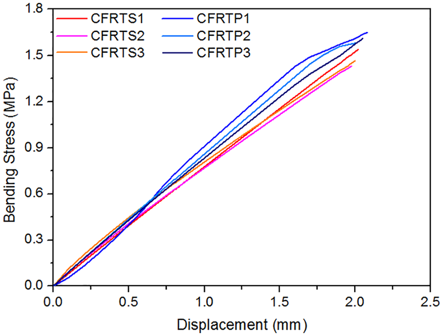
Stress versus displacement curve obtained from three-point bending test for CFRTP and CFRTS.
Impact energy
Figure 14 shows impact absorbed energy per cross section area. The value is the impact absorbed energy divided by the cross section area (0.8 cm2) of the specimen. The cross section area of CFRTP and CFRTS are 11.5 and 10.6 mm2, respectively. Figure 14(a) is impact absorbed energy per cross section area for sandwich CFRP between steel and Figure 14(b) is that of only CFRP. In all five specimens, the impact absorbed energy per cross section area of CFRTP with steels was higher than that of CFRTS with steels. The average value of CFRTP with steels is 227.0 J/cm2, and the average value of CFRTS with steels is 218.4 J/cm2. Even though the thickness difference between CFRTP and CFRTS was mere 0.09 mm, the impact absorbed energy per cross section area of the CFRTP was higher by 8.6 J/cm2 than CFRTS. The average impact absorbed energy per cross section area was 14.2 J/cm2 in the CFRTP alone, which was higher by 1.0 J/cm2 than CFRTS alone. These results showed that the impact absorbed energy per cross section area of CFRTP was slightly higher than that of the CFRTS, same as the results with the steel bonded.

Impact absorbed energy per cross section area by Charpy impact test: (a) sandwich CFRP between steel, and (b) only CFRP.
This is because hotmelt resin has higher elongation than epoxy resin. The difference between the impact absorbed energy and impact value is somewhat insignificant. However, since the impact value is divided by the cross section area of the specimen, the difference will be much larger for the cross section area.
Conclusion
In this study, the variables of forming time, temperature, pressure, lamination method, and pressurization count were applied to prepare the CFRTP with the compression molding method. The mechanical properties of the CFRTP prepared with the optimal lamination condition were compared with those of CFRTS. The obtained results are as follows:
With the lamination method wherein the hotmelt was inserted into each of the carbon fiber (a total of five sheets of carbon fiber and four sheets of hotmelt) by the compression molding, the optimal condition to enhance tensile strength of the composite material was found to be die temperature of 220°C, pressure of 6 MPa, and forming time for 10 min. The resulted tensile strength of the CFRTP was 400 MPa.
The prepreg was prepared with the one sheet of the hotmelt and another one sheet of carbon fiber by applying the process variables of die temperature at 220°C, pressure at 6 MPa, and forming time for 10 min with the compression molding method. Five sheets of the prepared prepregs were laminated under the same conditions to prepare CFRTP. The tensile strength of the CFRTP prepared with this method was 425 MPa. When the CFRTP was pressurized twice more under the same conditions, the tensile strength was increased to 495 MPa.
The tensile strength of the CFRTS prepared under the same laboratory condition for the lamination condition (epoxy prepreg was laminated at temperature 140°C, pressure at 0.5 MPa, and forming time for 30 min. with the compression molding) suggested by Lee and Kang 18 was 718 MPa. The resulting tensile strength of the CFRTP was lower by 223 MPa than that of CFRTS.
The flexural strength of CFRTP from three-point bending test is improved than CFRTS. The CFRTP can be applied to automobile components such as center pillar. Recently, M.S. Lee et al.18,22 manufactured and applied CFRTS/Steel hybrid composite materials to automobile body part as alternative material. Furthermore, the average impact absorbed energy per cross section area is 14.2 J/cm2 in the CFRTP, which is higher by 1.0 J/cm2 than CFRTS. If this CFRTP is applied to automobile body part, the lightweight and fuel efficient in the automobile industry using alternative material can be expected to promote.
The study results are different from general opinion that thermo-softening CFRP has lower properties than thermo-setting CFRP. Therefore, more studies need to be conducted for the compression molding method for the CFRTP in the future.
Footnotes
Handling Editor: James Baldwin
Declaration of conflicting interests
The author(s) declared no potential conflicts of interest with respect to the research, authorship, and/or publication of this article.
Funding
The author(s) disclosed receipt of the following financial support for the research, authorship, and/or publication of this article: This work was supported by the National Research Foundation of Korea (NRF) grant funded by the Korean government (MSIP) through the GCRC-SOP (No. 2011-0030013). This work was also supported by the National Research Foundation of Korea (NRF) grant funded by the Korean government (MSIT) (No. NRF-2020R1F1A106 7912). This work was also supported by the National Research Foundation of Korea (NRF) grant funded by the Korea government (MSIT) (No.2017R1A2B4007884).