
Abstract
The carbon fiber–reinforced plastics have gained considerable attention in the aerospace industry in recent years. Drilling of carbon fiber–reinforced plastic is relatively difficult with too much fiber delamination and pulling out in the entry and exit of the holes. As an advanced hole-making technology, helical milling is being developed in machining of carbon fiber–reinforced plastic, in which the tool moves on a helical course to the workpiece. Experiments were carried out on helical milling of carbon fiber–reinforced plastic, the effects of the cutting parameters and tool wear on the cutting forces are analyzed, and the relation between hole quality and cutting forces is also discussed. In order to simulate the cutting forces under different cutting conditions, the mechanistic modeling technique is used to predict cutting forces in helical milling of carbon fiber–reinforced plastic, and the cutting force coefficients are identified and corrected based on the experimental data. The results show that the established model can be used to predict the cutting forces in the helical milling process.
Introduction
Helical milling (also called as orbital drilling) is an advanced hole-making technology mainly for typical difficult-to-cut materials, such as carbon fiber–reinforced polymers (CFRP) and titanium alloy. As a kind of new structural materials with high strength-to-weight ratio, high stiffness-to-weight ratio, and the abrasive nature, CFRPs are increasingly being used in the aerospace industry in aircraft fuselage and wings. 1 However, in order to ensure the intensity and rigidity of the connection with other frames, the holes must be precisely made. The machining accuracy of the composite component has become an important factor to affect the performance, reliability, and service life. The most prominent problem of the CFRP is the lower processing efficiency caused by the rapid tool wear and poor quality of the workpiece.
The composite materials generally have two or more substances with completely different mechanical, physical, and chemical properties so as to obtain the performance and functionality which single-component materials do not possess. It is known from experimental investigations that the general cutting conditions applied to metals are not the most efficient or cost-effective for composite material and vice versa. 2 The main problems of hole-making defect are material cracking and delamination, burr and tear in the entry and exit of the holes, and large surface roughness or ultrapoor roundness error. In order to decrease the defects in the drilling of composite material, the shape of the drill, drill tip angle, drilling parameters (spindle speed and feed rate), and tool wear issues were studied widely in the drilling process. Tsao3,4 used the Taguchi method to optimize the drilling parameters (drill diameter ratio, feed rate, and spindle speed) based on the core-saw drill and step-core drill in the drilling of CFRP; the results showed that when the feed speed was 8 mm/min, spindle speed was 1200 r/min, diameter ratios were 0.55 and 0.74, and the axial force and hole defects came to a minimum value. Iliescu et al. 5 estimated and evaluated the axial force in the drilling of carbon fiber composites with coated and uncoated tools and found that the main factors affecting the axial force were feed rate, cutting speed, and tool wear. Gaitonde et al. 6 used the Taguchi optimization technology to research how to reduce the hole defects in high-speed drilling of CFRP; the evaluation index was selected as the entry defects and delamination factor under different spindle speeds, feed speeds, and attic angles. Jin et al. 7 analyzed the effect of fiber orientation, drilling force, drilling hot, cutting speed, and other factors on the drilling defect based on the CFRP and developed a new technology and new tool named as “grinding tool.” The corresponding studies on the hole-making mainly aimed at the influence of the axial force on the hole defect in the drilling process, and the ultimate goal was to achieve high-quality drilling for CFRP materials.
Cutting forces are important physics quantity in reflected cutting state, and the size of the cutting forces will directly influence the quality. Zhang et al. 8 set up a mechanistic model to predict the forces in the orthogonal cutting of unidirectional FRP with fiber orientation of 0°–90°. The cutting zone was analyzed with chipping, pressing, and bouncing regions, respectively. It showed that the model could predict the cutting forces with acceptable accuracy. The typical milling force model about CFRP was the study done by Kalla et al., 9 who utilized mechanistic modeling techniques to research the cutting forces in milling of CFRP by transforming specific cutting energies from orthogonal cutting to oblique cutting, and the cutting force coefficients were identified using Neural Network Committee method. It was shown that the method was more capable of predicting the cutting forces over the entire range of fiber orientations. Sahraie and Bahr 2 developed a new analytical method to predict the cutting forces using energy method for the orthogonal machining of unidirectional composites and verified the validity of the proposed model using experiment.
Cutting forces are related to many factors, such as cutting parameters, workpiece materials and tool. Simultaneously, the measure of the cutting forces is relatively easy. Therefore, it is necessary to establish the relationship between the cutting forces and the cutting parameters, so as to control the machining defect through the cutting forces by reasonable selection of the cutting parameters.
This article aims at analyzing the cutting forces in helical milling of CFRP. The corresponding cutting factors and hole-making quality related to the cutting forces are analyzed based on the experimental results. An analytical cutting force model based on the mechanistic modeling techniques is used to simulate cutting forces in helical milling of CFRP. In addition, the cutting force coefficients are corrected according to the experimental data, and the established model is tested through the cutting experiments.
Helical milling
According to the cutting principle of helical milling, the tool orbits around the axis of the hole while rotating with its own axis and feeds in the axial direction. In the cutting process, the holes with different diameters can be made using a single-diameter tool; discontinuous cutting not only reduces the number of the cutting tools but also makes good chip transportation; thus, the temperature in the cutting interface can be lowered. Small axial feed rate of tool center is not consistent with the conventional drilling, and the holes can be made with lower axial forces, thus reduce the delamination of CFRP. 1 Helical milling can represent a good alternative to the conventional drilling operations in machining of difficult-to-cut materials (Iyer et al., 10 Ni, 11 and Wang et al. 12 ).
To analyze conveniently, two coordinate systems are set up, as shown in Figure 1, where xOy is the workpiece coordinate system, point O is the hole center, x2O2y2 is the tool coordinate system, point O2 is the tool center,
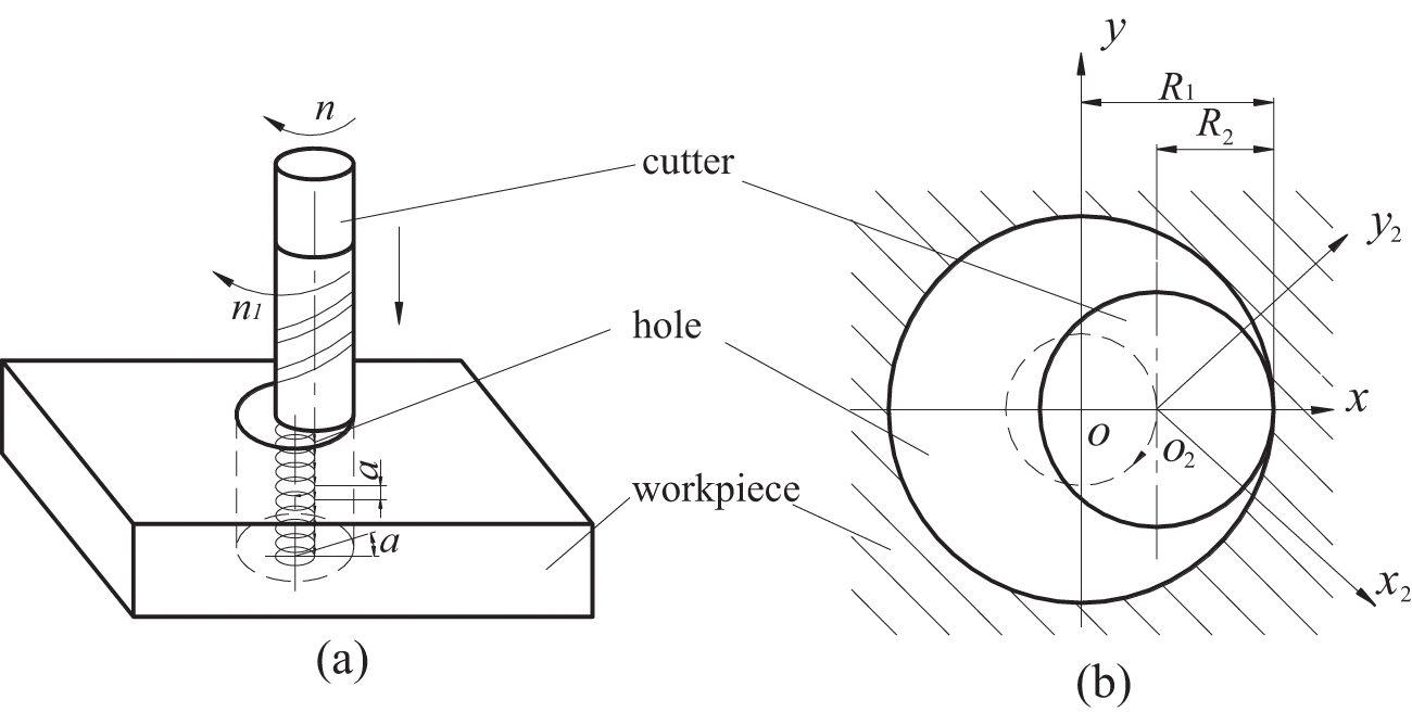
Kinematics of helical milling: (a) front view and (b) top view.

The feed speed of tool center in the xOy plane is calculated as

Supposed that N is the teeth number of the tool, the feed rate per tooth of tool center in the xOy plane is given by

The axial feed speed can be expressed as

The axial feed rate per tooth is as follows

The helix angle in the helical path of the tool is given by

Generally, the cutting parameters in the helical milling process are the spindle rotational speed, the orbital speed, the feed rate per tooth, the axial feed rate per orbit (depth of cut), and the offset of tool center, but these five cutting parameters are not independent of each other. Supposed that the tool offset
Experimental setup
A series of helical milling experiments were conducted for CFRP on a five-axis machining center DMC70V. Cutting forces were recorded using a Kistler dynamometer 9257B, which was connected to a Kistler charge amplifier. The output of the amplifier was transformed into the cutting forces through a computer storing the force signals versus cutting time using the LabVIEW software. Due to the bad influence of traditional cooling fluid on the performance of CFRP, machining tests were conducted under dry conditions (without coolant), and the chips were collected using a special vacuum tube, as shown in Figure 2. Full-factor experimental parameters were selected to carry out, as illustrated in Table 1; the rotational speed, feed rate per tooth, and axial feed rate per orbit were all selected with four levels.
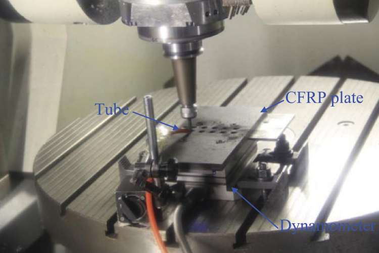
Experimental setup.
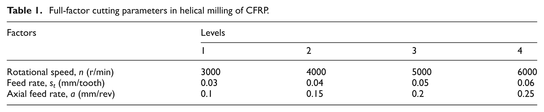
Full-factor cutting parameters in helical milling of CFRP.
The CFRP composite was unidirectional prepregs with a total fiber volume of 65%, fiber materials are carbon fiber (T700), and fiber quality is 130 ± 5 g/m2; matrix material is bismaleimide (BMI) with fiber orientation of 0°. The cross-sectional area of plate was 250 × 120 mm2 having a thickness of 10 mm. The 4-flute, 6-mm-diameter, and 55-mm-length special cutters with rake angle of 5°, helix angle of 35°, and TiAlN coating material were used in the tests. The hole diameters were 10 mm. Tool wear was measured using the tool microscope. In order to prevent obvious exit defect, such as fiber delamination and pullout in the cutting process, the plastic plate was placed under the CFRP plate. The hole entry delamination was observed using the KEYENCE VHX-600E microscope, and the surface roughness was tested using SVC-500 series surface roughness and contour instrument.
It was supposed that the workpiece was rigidly clamped on the machine table, the deflection of the tool caused by the cutting force was neglected, the cutting tool was sharp, and the effect of inclination angle on the cutting forces was ignored.
Influencing factors of cutting forces
Cutting forces were measured in the x, y, and z directions in the workpiece coordinate system. In order to analyze conveniently, the overall resultant force in the plane perpendicular to axial direction is calculated using the following equation

where Fx and Fy are the cutting forces in the x and y directions in the workpiece coordinate system, respectively; Fc is the resultant force in the xOy plane, as shown in Figure 3; and Ft and Fr are the tangential (feed) and radial direction (thrust) cutting forces, respectively Fz is the axial cutting force.
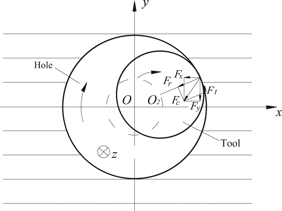
Cutting forces in the xOy plane.
Influence of cutting parameters on cutting forces
Influence of spindle rotational speed
It is known that tool cutting speed depends on the tool rotational speed and tool diameter; thus, the relation between spindle speeds and cutting forces also represents the relationship between the cutting speeds and cutting forces with consistent tool diameter. Other than the titanium alloy, higher spindle speed is beneficial to the machining quality of CFRP (Ni 11 ).
When the spindle rotational speeds change from 3000 to 6000 r/min, the feed per tooth is 0.04 mm and axial feed rate of every orbit is 0.1 mm, and the tool diameter remains constant with other unchangeable cutting parameters; the impact of the spindle speeds on the cutting forces is analyzed. The results are illustrated in Figure 4(a): macro-axial cutting forces are always larger than the radial resultant forces, and all the cutting forces (axial and resultant directions) decrease with the increase of the spindle rotational speed with nonlinear relationship, but the decreasing scope of the axial forces is larger than the radial forces with the increase in the spindle rotational speed.
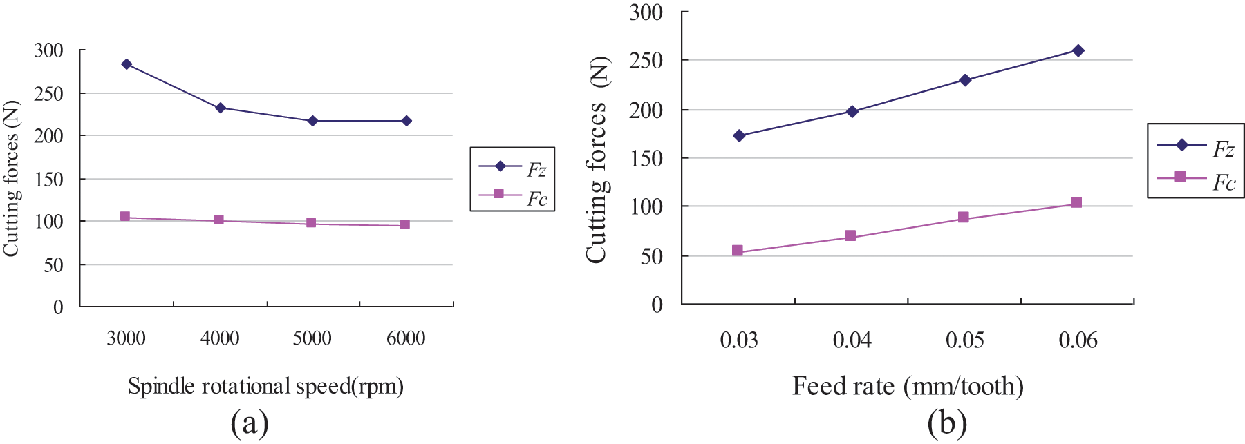
Influence of spindle rotational speed and feed rate per tooth on the cutting forces: (a) influence of spindle rotational speed on the cutting forces and (b) influence of feed rate per tooth on the cutting forces.
Effect of feed rate per tooth of the tool center
When the spindle rotational speed is 4000 r/min, axial feed rate per orbit is 0.1 mm, the feed rates per tooth change from 0.03 to 0.06 mm, and the influence of the feed rate per tooth of the tool center on the cutting forces is illustrated in Figure 4(b). The feed rate per tooth of the tool center is an important parameter in the helical milling process. It can be seen that the cutting forces have a nearly linear relation to the feed rate per tooth, and when the feed per tooth increases, two-direction cutting forces also increase gradually, and the increase extent of the axial forces is larger than the radial resultant force.
Influence of axial feed rate
While the spindle rotational speed is also 4000 r/min, feed rate per tooth is 0.04 mm, and axial feed rate per orbit changes from 0.1 to 0.25 mm, the influence of axial feed rate on the cutting forces is studied under other constant cutting parameters. The results are illustrated in Figure 5. It can be seen that the influence of the axial feed rate on the axial cutting force is larger than the influence on the radial resultant force, although the axial and radial cutting forces increase with the increase of the axial feed rate, but the relation between the axial feed rate and cutting forces is nonlinear whether in the axial direction or in the radial direction.
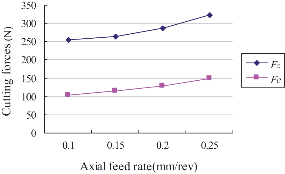
Influence of axial feed rate on the cutting forces.
Influence of eccentricity
To a tool with fixed diameter, the changeable scope of the machined hole diameter is not very large, different offsets will bring holes with different diameters. Generally, the ratio of tool diameter to hole diameter ranges from 55% to 90% (Ni 11 ). For example, the changeable scope of the eccentricity is about 0.5–2.3 mm for 6-mm-diameter tool. If required to analyze the influence of the eccentricity, the tool center offset should be changed while keeping other cutting parameters constant. When the spindle rotational speed is 4000 r/min, feed rate per tooth is 0.04 mm, and axial feed rate per orbit is 0.1 mm, the eccentricities change from 1 to 2, that is, when the hole diameter is changed from 8 to 10 mm with 6-mm-diameter tool, the effect of the eccentricities on the cutting forces is studied.
It can be seen from Figure 6 that the cutting forces increase with the increasing eccentricity, but the effect of the eccentricity on the cutting forces is not large, and the influencing trend can also be deduced from equations (2) to (5).
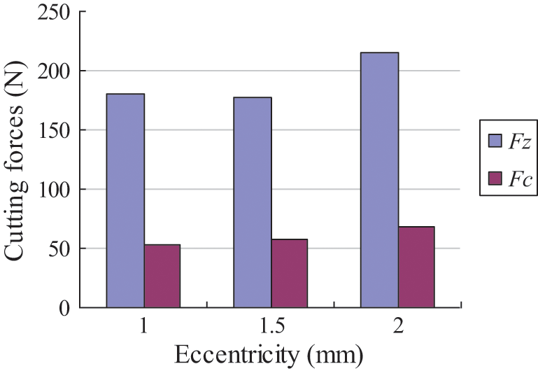
Influence of eccentricity on the cutting forces.
Influence of tool wear on cutting forces
When machining of fiber-reinforced plastics (FRPs), significant changes of the cutting edge occur due to the high fiber rigidity during cutting process. Rounding of the cutting edge is even proposed to be used as wear criterion for composite machining (Schulze et al. 13 ), which will bring change in the cutting forces and cutting quality problems. Therefore, it is very important to study the influence of the tool wear on the cutting forces for the CFRP material.
In order to analyze the influence of tool wear on the cutting forces, the same cutting parameters (spindle rotational speed: 5000 r/min, feed rate: 0.04 mm/tooth, and axial feed rate: 0.1 mm/rev) were taken as the experimental condition, and the results are shown in Figure 7.
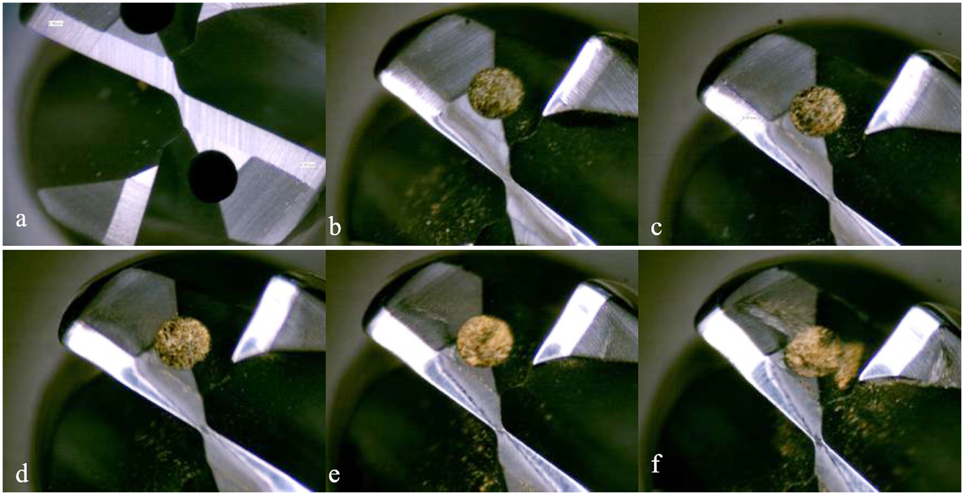
Tool wear state in the helical milling process: (a) the bottom edge of the new tool (b) the bottom edge of the tool with 10 holes made (c) the bottom edge of the tool with 23 holes made (d) the bottom edge of the tool with 39 holes made (e) the bottom edge of the tool with 53 holes made and (f) the bottom edge of the tool with 80 holes made.
Tool wear will get worse with the increase in the number of holes (Iliescu et al. 5 ). As shown in Figure 7, they are the wear state of bottom edge of special helical milling tool. The bottom edge of the new tool is illustrated in Figure 7(a), and it can be seen that the bottom edge is integrate; Figure 7(b) is the bottom edge while 10 holes were made, it can be seen that there is a slight wear of the cutting edges; when 23 holes were made, the wear state of the bottom edge becomes larger, as shown in Figure 7(c); Figure 7(d) is the bottom edge while 39 holes were made, the evident wear trace can be seen; while 53 holes were made, all the bottom edges show serious wear, as shown in Figure 7(e); Figure 7(f) is the bottom edge while 80 holes were made, the wear state further becomes worse, although there is no evident chipping and breakage, but the wear field becomes larger and larger. In all, the wear is smooth and uniformly distributed along the entire cutting edge with only the abrasion wear. It is not realistic to monitor tool wear at any time, so the changes of the cutting force in cutting process can be used to verify the degree of tool wear.
Both radial resultant and axial cutting forces are found to increase with the increase in the number of holes machined, as illustrated in Figure 8. When the number of holes increases, tool wear will get worse, that is, cutting forces will increase with the increase in the tool wear. While the fifth hole is machined, the radial resultant and axial cutting forces increase to about 44% and 24%, respectively, relative to the first hole, and when the 20th hole is machined, the two-direction cutting forces increase to about 10% and 2.9%, respectively, relative to the 15th holes. In addition, the increasing rate of cutting forces remains about less than 10% for the other holes, and the trend of forces is increasing with the number of hole-making, that is, there is a direct proportional relationship between the tool wear and cutting forces.
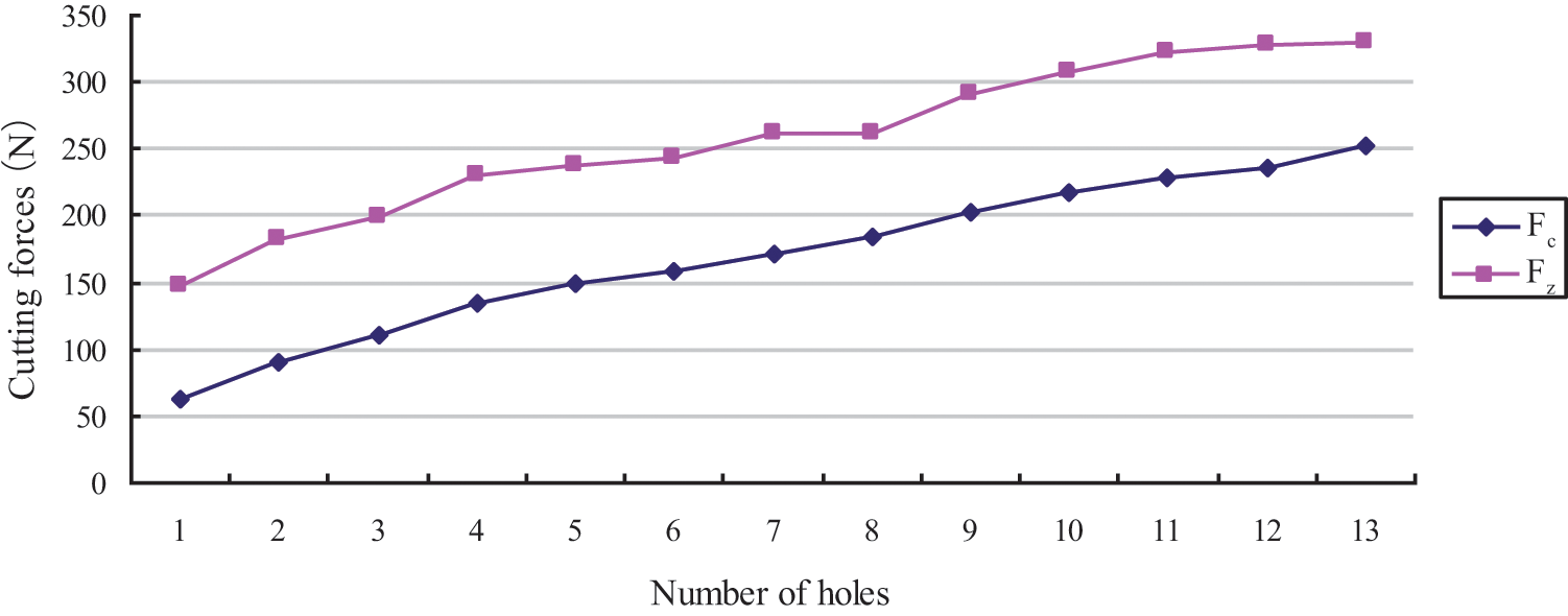
Effect of number of holes on the cutting forces.
Surface roughness of the inner wall and defect in the entry of the hole
For the unidirectional CFRP with fiber orientation of 0°, the surface of the inner wall of the hole is relatively rough with about Ra6.3 µm at 135° clockwise to the x-axis, while the rest of the roughness in the inner wall of the hole reach Ra0.3–0.6 µm, but the delamination in the entry is found at 45° clockwise to the x-axis, as illustrated in Figure 9(a).
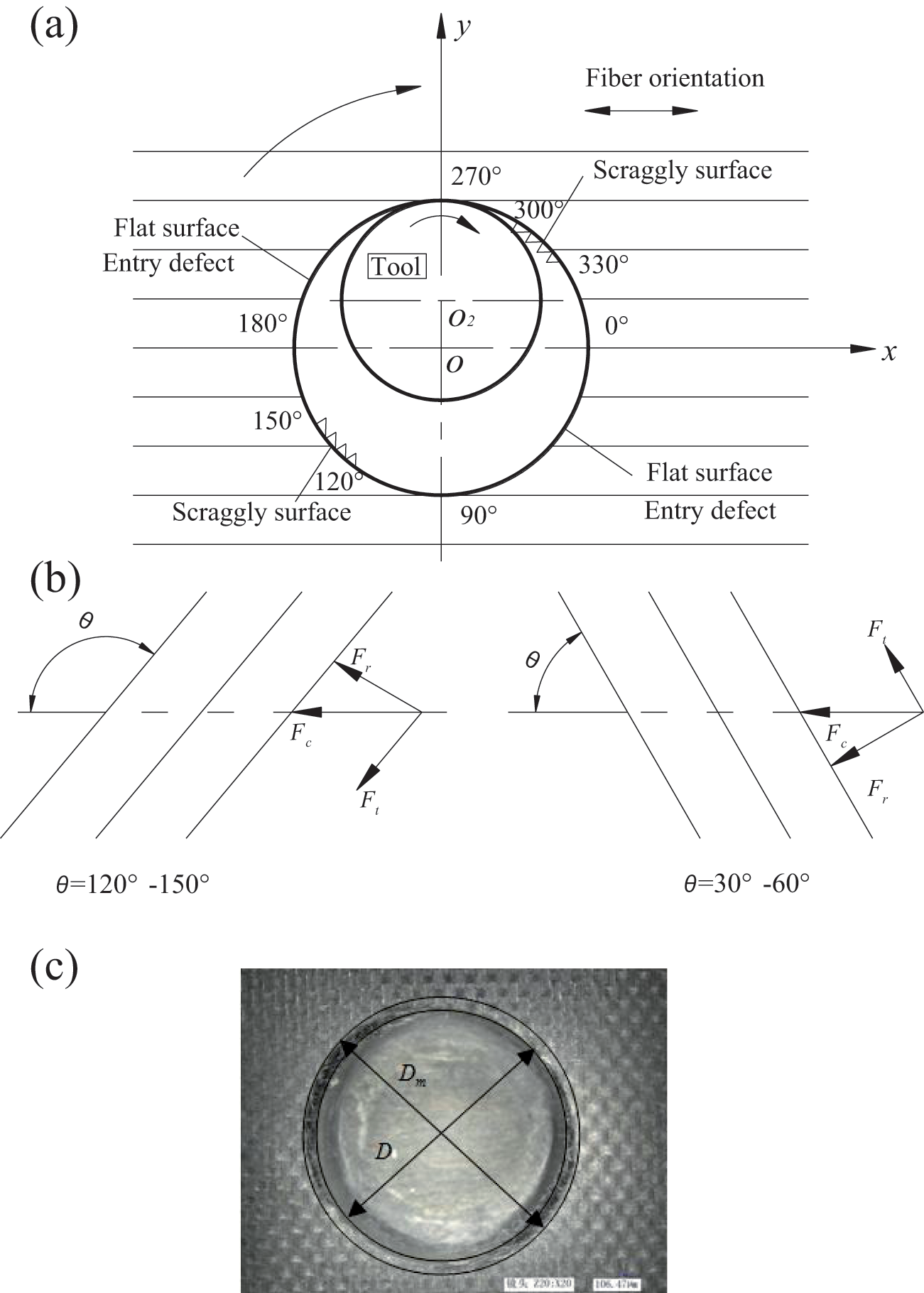
Surface state and cutting forces in different directions and places of the hole: (a) surface state of the hole, (b) cutting force analysis in different positions, and (c) entry delamination of the hole.
It is known that fiber orientation has a great influence on the surface quality (Wang and Zhang 14 ). Due to the tool rotates and orbits simultaneously in the helical milling of unidirectional CFRP with fiber orientation of 0°, the feed direction changes continuously with fixed periodicity, which can be thought that the tool feeds in a fixed direction, but the fiber orientation changes from 0° to 360°. Supposed that θ is the angle between fiber orientation and machining direction, in order to analyze the inner wall surface roughness and defect in the entry, the cutting forces in different positions are illustrated in Figure 9(b); when the tool is located at 135° (120°–150°) and 315° (300°–330°) clockwise to the x-axis, that is, θ is 135° (120°–150°), the tool feeds forward, the cutting force in the xOy plane is decomposed into tangential and radial directions, the radial force is toward the external of the hole, and the fiber gets a relatively weaker support from the surrounding materials, which will lead to severe fiber bending, so the machined surface is very rough, while the tangential force is toward the internal of the hole, which will compress the material along the fiber orientation and avoid entry defect. When the tool is at 45° (30°–60°) and 225° (210°–240°) clockwise to the x-axis, that is, θ is 45° (30°–60°), the tool also feeds forward, the cutting force is also decomposed into tangential and radial directions, the radial force is toward the internal of the hole, and the fiber will be better supported by the back material; here, the fiber bending is small; thus, the smooth machined surface of the inner wall can be achieved. But when the tangential force is toward the external of the hole, tensile stress will increase the cutting difficulty, especially in the entry of holes, so the entry defects such as burrs and delamination are found, as shown in Figure 9(a) and (c). For the rest of the angle domain, the tangential and radial forces can also be decomposed as above.
Burr formation is a complex interaction of various factors, such as tool, workpiece, and cutting parameters (Brinksmeier and Fangmann 15 ). Considering the material characteristic of CFRP, longer burrs can be cut easily, but the bigger root of the burrs will bring delamination defect to the entry of holes, so according to the study done by Hintze et al., 16 the delamination defect is selected as the appraisable index of the entry quality of the holes.
As shown in Figure 9(c), the delamination factor Fd is expressed as follows (Chen 17 )

where Dm is the maximum diameter of the damaged zone and D is the ideal diameter of the hole. The delamination factors are calculated based on the full-factor experiment in the helical milling, as illustrated in Table 1, and it is shown that all the delamination factors basically lie in the range of 1.04–1.14.
The relationship between delamination factors and cutting forces is illustrated in Figure 10. It can be seen that delamination factors increase with the increase in the tangential cutting forces, while when the axial cutting force increases, the delamination factors basically remain constant. It shows that the correlation relationship between tangential forces and delamination factors is the strongest in all. The regression function between tangential forces and delamination factors can be expressed as
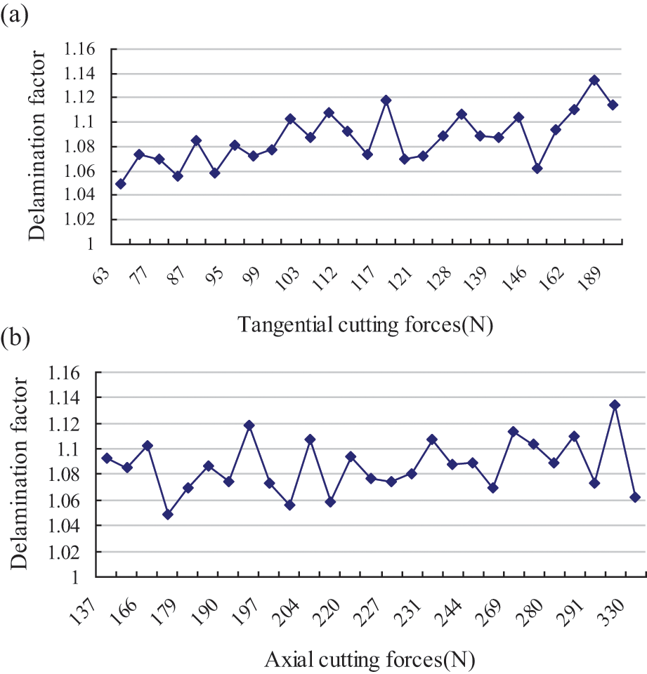
Relation between delamination factors and cutting forces: (a) relation between delamination factors and tangential cutting forces and (b) relation between delamination factors and axial cutting forces.

where Ft is tangential force.
Analytical model of cutting forces
Mechanistic model of cutting forces
As shown in Figure 11, θ is the tool position in the workpiece coordinate system, measuring from y-axis with clockwise direction, and φ is the tool position in the tool coordinate system, measuring from yc-axis with clockwise direction. The helical milling process is double periodicity because of the rotation and orbit of the tool. Supposed that the helix angle of the tool is β, then the instantaneous immersion angle
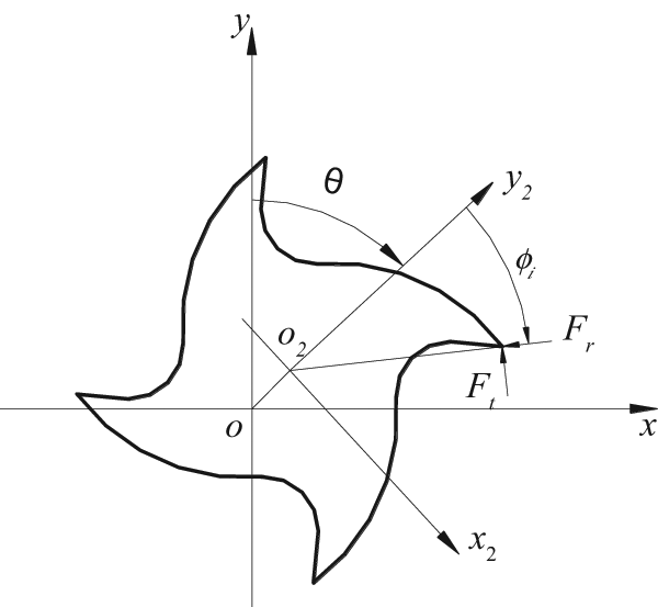
Workpiece and tool coordinate systems in the helical milling process. 12
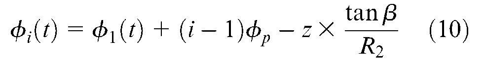
where

Mechanistic modeling method is the most robust and efficient technique in modeling of the cutting forces, which has been widely applied. The cutting forces are proportional to the uncut chip area by the cutting force coefficients. The undeformed chip thickness at a certain location on the cutting edge can be estimated as follows

where st is feed rate per tooth, hi is the immersion-dependent chip thickness cut by tooth i, and φ i is the tool rotational angle in the tool coordinate system, as shown in Figure 11.
According to the metal cutting theory, there is a complex nonlinear relation between cutting forces and cutting parameters. To calculate cutting forces in the helical milling process, the tool can be regarded as an end-milling cutter with bottom edges, and the tool is dispersed into a stack of disks, where each disk has
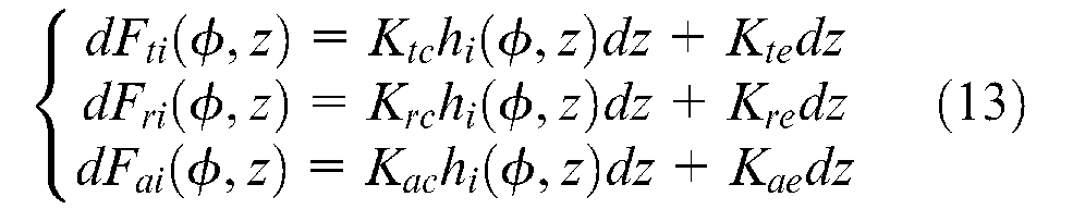
where
Because CFRP materials are different from metal, plastic deformation stage in the metal cutting process does not appear in the CFRP cutting process, and the chip formation mechanism is a serial process of material fracture called as brittle fracture with powder form, and it is extremely difficult to measure chip thickness and calculate the shear plane angle as is done in the metal machining process. In addition, the cutting process consists of a series of brittle fractures, and hence, frictional force generated by the chip sliding up the tool face can be negligible in the machining of the CFRP, that is, although equation (13) is similar as the cutting forces formula while helical milling of titanium alloy (Wang et al. 12 ), the physical meaning is a little different. Equation (13) is transformed into workpiece coordinate system
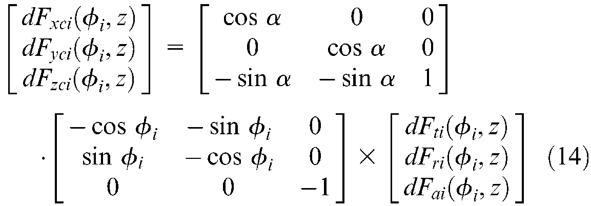
where
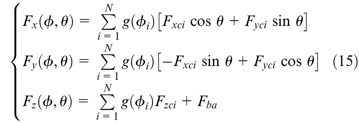
where

where
Identification of cutting force coefficients
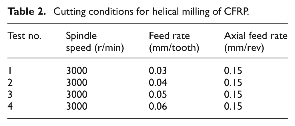
In order to identify the cutting force coefficients, single-factor cutting experiment (constant spindle speed and axial feed with different feed rates per tooth) was selected to analyze, as shown in Table 2.
Cutting conditions for helical milling of CFRP.
The average-based method is utilized to identify the cutting force coefficients according to the cutting forces measured in the helical milling experiments. The result is shown in Table 3.
Estimated
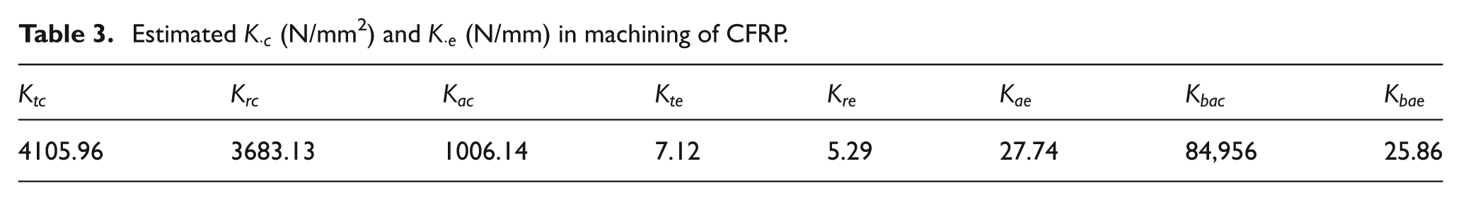
It can be seen from Table 3 that the three rubbing or plowing cutting force coefficients
Comparison of measured and simulated cutting forces
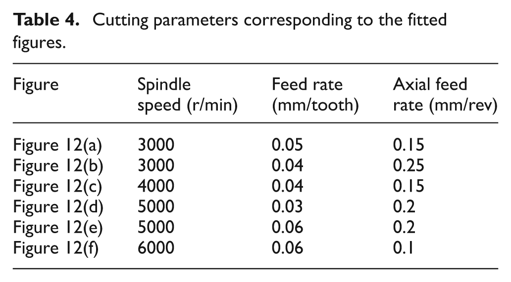
Cutting parameters illustrated in Table 4 are used to verify the cutting force coefficients and calculate cutting forces based on the actual conditions. Known from equations (4), (5), and (16),
Cutting parameters corresponding to the fitted figures.
Due to the cutting parameters in Figure 12(a), the cutting force coefficients are consistent with the conditions of identification, and the simulated result using the identified cutting coefficients is fitted well to the measured values; in Figure 12(b), the axial feed rate relative to the cutting parameters in Figure 12(a) increases 67%, and the spindle speed remains unchanged; thus, the fore six cutting force coefficients all increase 67%, and the fitted error of the measured forces and simulated value is small; while for Figure 12(c), the spindle rotational speed increases 33%, the axial feed rate remains unchanged, in order to receive the better fitted effect between the measured and simulated forces, the cutting coefficients also increase 33%; in Figure 12(d), the spindle rotational speed increases 67%, axial feed rate increases 33%, so the final cutting coefficients increase 1.23 times, and the cutting forces are fitted well with the measured forces; for Figure 12(e), the spindle rotational speed increases 67%, axial feed rate increases 33%, the cutting coefficients should increase 1.23 times, similar to Figure 12(d), but the increase in the feed rate results in the increase of the undeformed chip thickness, and the actual cutting coefficients only increase 33%, thus the cutting forces are fitted well to the measured cutting forces.
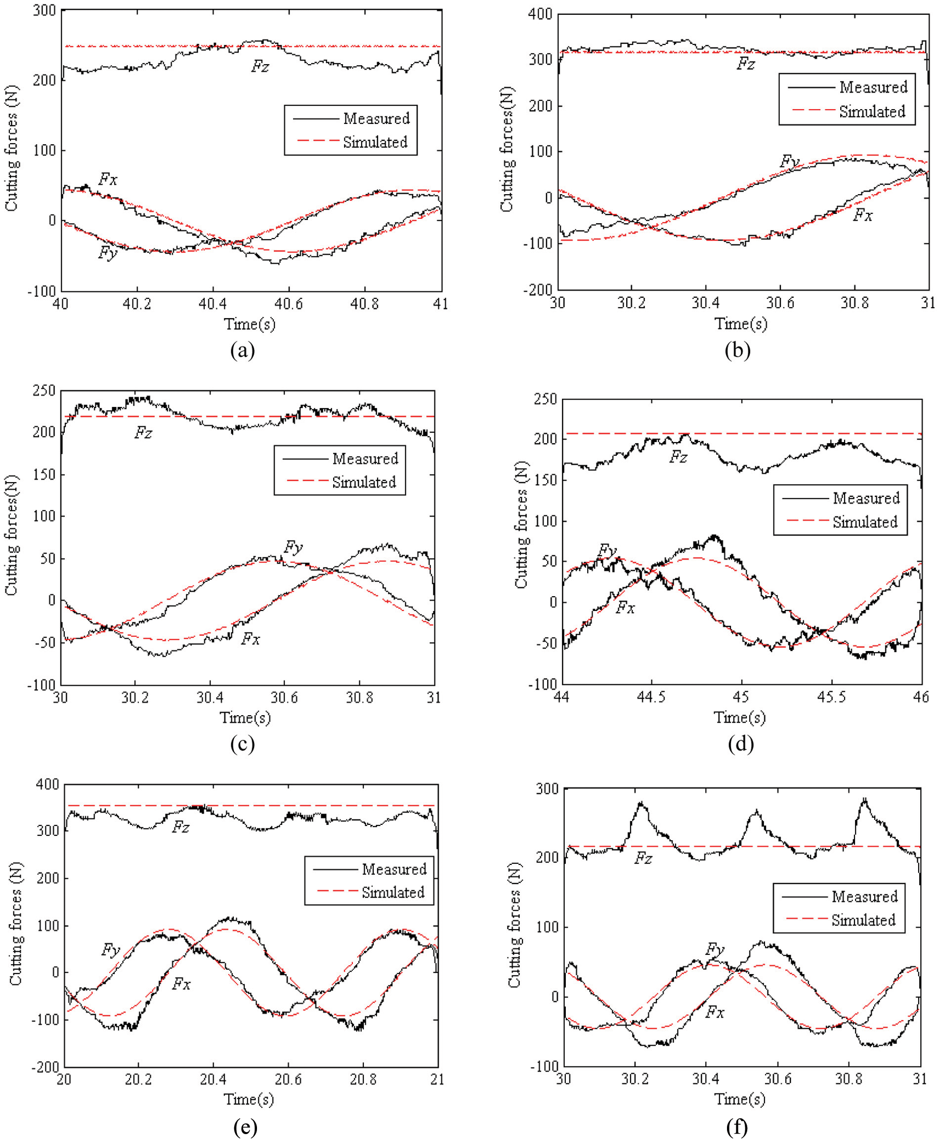
Comparison between measured and simulated cutting forces: (a) spindle speed: 3000r/min, feed rate: 0.05 mm/tooth, axial feed rate: 0.15 mm/rev (b) spindle speed: 3000 r/min, feed rate: 0.04 mm/tooth, axial feed rate: 0.25 mm/rev (c) spindle speed: 4000 r/min, feed rate: 0.04 mm/tooth, axial feed rate: 0.15 mm/rev (d) spindle speed: 5000 r/min, feed rate: 0.03 mm/tooth, axial feed rate: 0.2 mm/rev (e) spindle speed: 5000 r/min, feed rate: 0.06 mm/tooth, axial feed rate: 0.2 mm/rev and (f) spindle speed: 6000 r/min, feed rate: 0.0 6mm/tooth, axial feed rate: 0.1 mm/rev.
In Figure 12(f), the spindle rotational speed increases two times relative to Figure 12(a), axial feed rate decreases 67%, and the cutting coefficients should increase 34%, but the fitting error is relatively large; the main reason analyzed lies in the size effect (Yun and Cho 19 ). Here, the axial feed rate is only 0.1 mm, known from the size effect; when the axial feed rate is small, the cutting force coefficients will become larger, the cutting coefficients are adjusted to 1.2 times relative to the original value, and the fitting effect is obtained. In addition, when the spindle rotational speed is 6,000 r/min, feed rate is 0.02 mm/tooth, and the axial feed rate is 0.1 mm/rev, according to the above-mentioned analysis, cutting force coefficients should be 1.33 times to the coefficients in Figure 12(a), but when the cutting coefficients are adjusted to 4.5 times to the coefficients in Figure 12(a), a better fitting effect is obtained; thus, the difference is very large relative to the analytical result. The reason may be due to small undeformed chip thickness, that is, the feed rate per tooth and the axial feed rate are all small (0.02 and 0.1 mm), the size effect will take an active part, and cutting force coefficients become very large. When the feed rate per tooth and the axial feed rate are all large, the undeformed chip thickness also becomes large, and the cutting coefficients will become small relative to the theoretical analysis, as shown in Figure 12(e).
Regression model of the cutting force coefficients
Known from fore analysis, when the cutting parameters and undeformed chip thickness are relatively small, the relationship is exponential function between the cutting force coefficients and cutting parameters (Araujo et al. 20 ), and thereby, the relationship between the cutting force coefficients and cutting parameters can be established as follows

where K represent the six cutting coefficients (
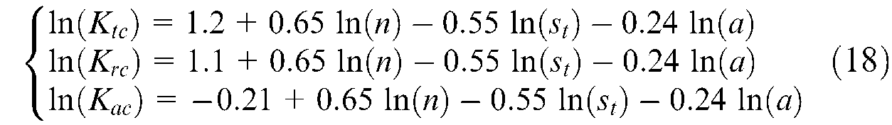
Due to the remaining three cutting force coefficients,
As shown in Figure 13(a), the spindle speed is 5000 r/min, feed per tooth is 0.06 mm, and axial feed rate every orbit is 0.15 mm, while in Figure 13(b), the spindle speed is 6,000 r/min, feed per tooth is 0.02 mm, and axial feed rate every orbit is 0.1 mm the dashed lines express the simulated cutting force using cutting force coefficients calculated by the regression equation (18), which basically capture the change state of the measured cutting forces.
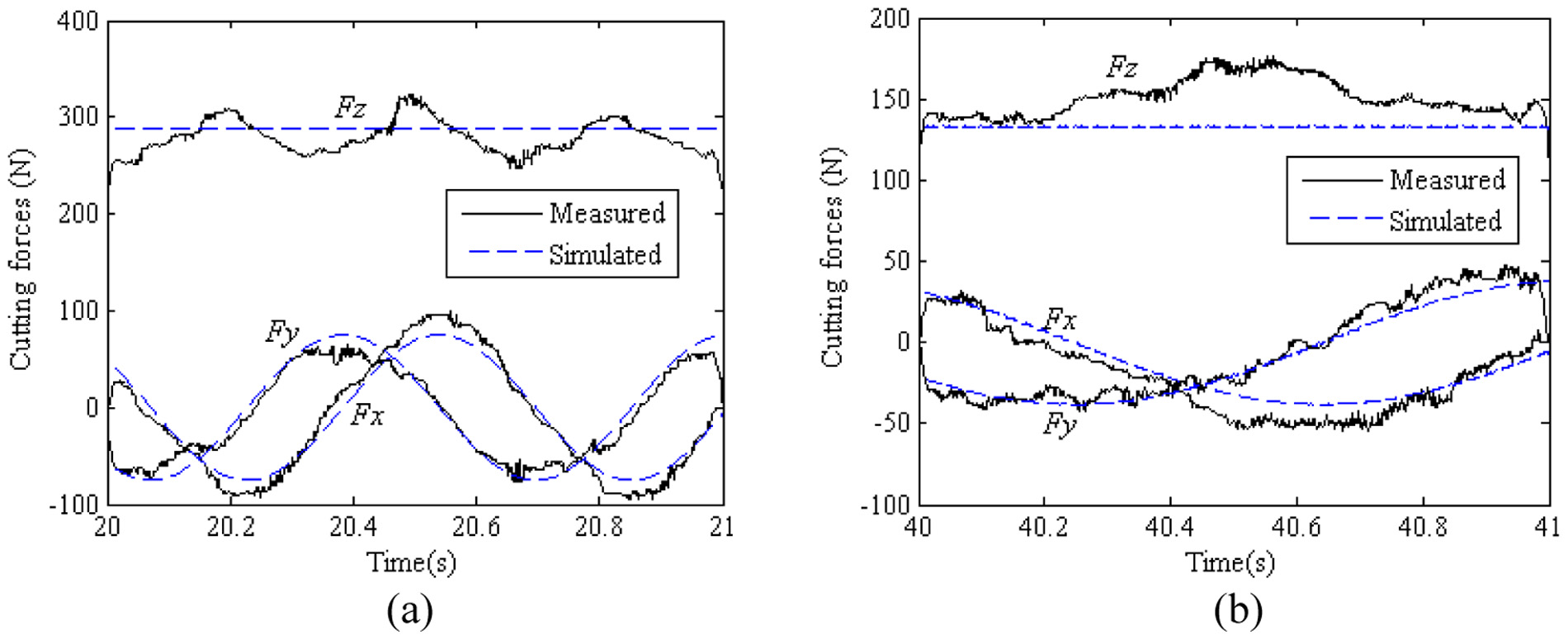
Fitted drawing between simulated and measured cutting forces: (a) spindle speed: 5000 r/min, feed rate: 0.06 mm/tooth, axial feed rate: 0.15 mm/rev and (b) spindle speed: 6000 r/min, feed rate: 0.02 mm/tooth, axial feed rate: 0.1 mm/rev.
Comparing the simulated value to the measured maximum value of three-direction cutting forces in Figure 13, the results show that there lies in error between the simulated forces and measured value, and the error value does not exceed 18%. The result shows that on the basis of the recognition of the cutting force coefficients, simulated cutting forces can be used to predict the change of the cutting forces in the cutting process.
Conclusions
As an advanced hole-making technology, helical milling will be used widely in aerospace industry. Because the performance of CFRP is different to the metal, the chip formation is a complex process with matrix damage and fiber breakage and hole quality is very important for the CFRP materials. This article studied cutting forces and hole quality in the helical milling of CFRP. The following conclusions are drawn.
The influence of cutting variables on the cutting force during helical milling of CFRP is analyzed based on the cutting experiments. The results show that radial resultant and axial cutting forces will decrease with the increase of the cutting speed and increase with the increase in the feed rate per tooth and axial feed rate. Finally, the influence of tool wear on the cutting force is also analyzed. The results show that the larger the tool wear, the larger the cutting forces.
For the unidirectional CFRP, the inner surface of the hole is relative scraggly at 120°–150° (300°–330°) scope clockwise to the x-axis, while other surface is slick; the hole entry defect is relative serious in 30°–60° (210°–240°) clockwise to the x-axis, although the surface of the wall of the hole is flat. The main reason lies in the effect of angle between fiber orientation and cutting direction on the cutting forces. The entry defect of the holes is analyzed through delamination factor, and all the delamination factors lie in between 1.04 and 1.14. The functional relation between the delamination factor and tangential force is set up.
Mechanistic modeling technique is used to predict cutting forces in helical milling of CFRP, and the action of the bottom edge is also considered in the modeling. The cutting force coefficients are identified and corrected through a series of cutting experiments, and the relation between the cutting coefficients and cutting parameters is set up through regression analysis. The results show that the simulated cutting forces can fit well to the measured values, and the error will not exceed 18%.
Footnotes
Funding
The study was supported by the natural science foundation of Tianjin (11JCZDJC22800), Sci-tech Support Program of Tianjin (09ZCKFGX03300), and National Engineering and Research Center for Commercial Aircraft Manufacturing (SAMC11-JS-07-215).