
Abstract
To address the special agronomic requirements of wide–narrow row planting of rice potted-seedlings, this paper proposes an inclined transplanting mechanism that achieves wide–narrow row planting under the seedling gate with an equal row spacing of 300 mm through the inclination angle of the inclined transplanting mechanism. The implementation scheme of the wide–narrow row transplanting mechanism (WNRTM) was determined, and its transmission scheme was designed. A kinematic model of the transplanting mechanism was established based on the basic configuration of the variable-speed non-circular planetary gear train. Using the self-developed optimization design software for transplanting mechanisms, a set of optimal design parameters was obtained. Under these optimal parameters, virtual and physical prototypes of the transplanting mechanism were constructed, and the transmission accuracy and motion characteristics of the mechanism were verified via virtual simulation and bench tests. Bench test results indicate that the distance between the seedling picking points on both sides of the designed inclined transplanting mechanism is 305 mm, while the distance between the planting points on both sides is 195 mm. These results meet the agronomic requirements for wide–narrow row transplanting and achieve the goal of wide–narrow row planting under the seedling gate with a fixed row spacing of 300 mm.
Keywords
Introduction
Rice is one of the primary food crops for humanity, serving not only as the foundation of human survival but also bearing significance for social stability, economic development, and ecological health. 1 As a key link in ensuring food security and promoting rural development, enhancing the mechanization level of rice cultivation has become a critical objective in current agricultural policies. 2
Rice cultivation methods include direct seeding and transplanting. Transplanting involves nurturing seedlings in substrates such as biochar in greenhouses or plastic tunnels until they reach the transplanting stage, and it can be categorized into two types: carpet seedling transplanting and pot seedling transplanting.3–6 During pot seedling transplanting, the seedlings are transplanted with their substrate, which avoids root damage, eliminates the seedling recovery stage, promotes early and more tillering, enhances lodging resistance, and increases yield by an average of 9.0% compared to machine-transplanted carpet seedlings. As the number of tillers increases, the lower parts of rice plants require more sunlight and ventilation; otherwise, the stems will elongate, making them more prone to diseases and lodging. 7 Therefore, Chinese scholars have proposed a wide–narrow row pot seedling transplanting model based on China’s agronomic requirements, climatic conditions, and geographical environments, where pot seedlings are planted in alternating wide and narrow rows. 8 Wide rows improve ventilation and light transmission, facilitating mechanical operations; narrow rows increase planting density and suppress weed growth. Wide–narrow row planting of rice potted-seedlings can balance the growth relationship between the population and individuals, improve yield, and better adapt to agronomic and environmental needs.9,10 However, due to the lack of WNRTMs, manual labor remains the only way to implement wide–narrow row transplanting, which significantly dampens farmers’ enthusiasm for this method. 11 Thus, there is an urgent need to develop a practical WNRTM.
South Korea has developed a five-bar seedling picking mechanism composed of a linkage-slider assembly, which includes a frame, drive crank, connecting rod, swing rod, slider, and slideway. 12 During operation, the crank rotates, and the swing rod forms a specific motion trajectory under the constraint of the slider to complete the seedling picking action. However, the linkage mechanism exhibits large inertia force, making it prone to significant vibrations at high speeds; thus, it is only suitable for low-speed transplanting. Additionally, the slideway is prone to wear. The four-bar seedling picking mechanism designed by Edathiparambil Vareed Thomas from India 13 can achieve direct seedling insertion, but it suffers from low success rate, low efficiency, and high vibration levels, thus failing to be widely adopted. Han et al. developed a series of slideway-type pot seedling transplanting mechanisms,14–17 which are unsuitable for high-speed transplanting and suffer from slideway wear issues. These aforementioned transplanting mechanisms have multiple drawbacks, including complex structures, high costs, and low efficiency, limiting their popularization. In contrast, planetary gear train-based transplanting mechanisms can complete four actions (seedling picking, seedling conveying, planting, and return stroke) using a single mechanism. They feature compact structures, continuous and stable operation, and low costs, thus becoming a key research direction in transplanting machine development. 2 Wang et al. 18 proposed a “pot-clamping” transplanting mechanism for rice wide–narrow row transplanting. Driven by a combination of planar non-circular gears and non-conical gears, the transplanting arm achieves a “beak-shaped” transplanting trajectory. However, the seedling picking success rate is relatively low during high-speed transplanting. Xu et al. 19 designed a gear-train-type WNRTM for ratoon rice, driven by a combination of planar non-circular gears and helical gears. Virtual simulations and prototype tests showed that the actual motion trajectory and posture of the prototype are basically consistent with the theoretical design. Sun et al. 20 developed a transplanting mechanism for wide–narrow row transplanting. By establishing a kinematic model of the 2R mechanism and applying a parameter solution method for spatial planetary non-circular gear trains based on three given poses, they derived the parameters and transmission ratios of the non-circular gears. The transplanting mechanism, constructed by combining non-circular gears and helical gears, had its performance verified through simulations and experiments. However, the aforementioned transplanting mechanisms using planar non-circular gears and non-bevel gears demand high gear manufacturing precision, resulting in high costs. Moreover, they face the issue of oblique seedling picking during operation.
This research presents an inclined three-arm transplanting mechanism for pot-type rice seedlings in wide–narrow row configurations, engineered based on non-circular gear trains. The variable-velocity transmission of non-circular gear trains is leveraged to generate the specialized trajectories and postures required for pot-seedling transplanting, while two planar-trajectory transplanting mechanisms mounted on the same transmission housing of the inclined transplanter facilitate wide–narrow row operations. A kinematic model of the transplanting mechanism was developed, the inclination angle of the transmission housing was analyzed, and structural design, virtual simulation, and prototype testing were conducted to validate the operational feasibility of the WNRTM.
This research achieves the goal of enabling a fixed-row-spacing transplanter to perform wide–narrow row rice transplanting by only configuring a WNRTM, through the method of inclining the transplanting mechanism. Meanwhile, it solves the problem of inclined seedling picking that occurs when the spatial non-circular gear train transplanting mechanism is used for wide–narrow row transplanting. This study provides a reference idea for wide–narrow row transplanting of rice pot seedlings.
Materials and methods
Wide–narrow row transplanting scheme
To achieve the planting mode of wide–narrow rows, it is necessary to redesign and configure the structure of the transplanting machinery. The mutual conversion between wide–narrow rows follows a basic principle when ensuring that the number of seedlings per unit area remains unchanged: the increase in wide row spacing is equal to the decrease in narrow row spacing. This principle ensures that the overall density of rice transplantation remains unchanged even when adjusting the row spacing, avoiding any impact on the growth density and yield of rice. By adjusting the wide–narrow row spacing, the arrangement of seedlings can be flexibly changed. In this adjustment process, increasing the wide row spacing will result in a corresponding decrease in the narrow row spacing, ensuring that the number of seedlings per unit area remains constant, that is, keeping the total number of rice plants unchanged.
As shown in Figure 1, area A shows a conventional equal-row spacing transplanting mechanism with a seedling picking distance of 300 mm and a row spacing of 300 mm after transplanting. Area B shows a transplanting schematic of a WNRTM which is designed with a seedling picking distance of 300 mm, a wide row spacing of 400 mm during transplanting, and a narrow row spacing of 200 mm.

Schematic diagram of WNRTM.
Composition and working principle
The inclined rice seedling pot WNRTM designed in this study has a single-side transplanting mechanism configured with three transplanting arms and one non-circular gearbox. The transplanting mechanisms on both sides are left–right symmetric, and there is a bevel gearbox in the middle that transmits power and ensures the synchronous rotation of the transplanting mechanisms on both sides, as shown in Figure 2(a). The transplanting mechanisms on the left and right sides are identical in structure and have a mirror image relationship. Therefore, the right-side transplanting mechanism is taken as an example for structural description, as shown in Figure 2(b). The non-circular gear train of the transplanting mechanism is composed of three completely identical small non-circular gear trains. These three small non-circular gear trains have the same motion trajectory but a phase angles differ by

Schematic diagram of inclined rice potted-seedling WNRTM: (a) front view, (b) front view of the right transplanting mechanism, and (c) bevel gear transmission.
Taking one transplanting unit as an example, during operation, the planet carrier is hinged on the frame, obtains power transmitted by the bevel gearbox, and rotates at a constant speed relative to the frame. The sun gear is fixedly connected to the frame, while both the intermediate gear and the planet gear are hinged on the planet carrier. During operation, the planet carrier rotates clockwise, the sun gear meshes and rotates with the intermediate gear, and the intermediate gear meshes and rotates with the planet gear. The transplanting arm is fixedly connected to the planet gear. With the constant rotation of the planet carrier and the non-uniform transmission of the non-circular gear train, the transplanting arm performs circular motion with the planet carrier on the one hand, and performs non-uniform rotation relative to the planet carrier together with the planet gear on the other hand. The combination of these two motions enables the transplanting arm to achieve the transplanting trajectory and pose of rice seedling pots.
The transplanting arm components mainly consist of a transplanting arm cam, transplanting arm housing, spring, seedling clamp and U-shaped clamp, seedling pushing rod and bottom plate, as well as fork and fork roller. The cam is fixed to the gearbox housing, and the transplanting arm housing rotates together with the planetary gear; the spring is always in a compressed state, with one end resting on the cover of the transplanting arm housing and the other end connected to the seedling pushing rod; the fork is hinged inside the transplanting arm housing, and the fork roller can freely rotate on the fork, always closely adhering to the outer surface of the cam. When the fork roller lifts with the cam, the fork drives the seedling pushing rod to move toward the housing and compresses the spring, while the U-shaped clamp synchronously tightens inward, clamping the seedlings with the seedling clamping piece; when the fork roller enters the return stage, the spring releases energy to push the seedling pushing rod and U-shaped clamp outward, releasing the seedling clamp and loosening the seedlings. The seedling pushing bottom plate acts on the seedling potted substrate to complete the seedling pushing action. The continuous reciprocating motion of seedling picking, transportation, and placement is achieved.
Power is transmitted into the main drive shaft of the transmission box, and then the bevel gears inside the transmission box transmit power to the planet carriers of the transplanting mechanisms on both sides, driving the transplanting mechanisms to work. The bevel gears inside the transmission box include four gears, as shown in Figure 2(c): driving bevel gear is fixedly connected to the main drive shaft and meshes with the driven large bevel gear; the right driven small bevel gear is fixedly connected to the driven large bevel gear, and the left driven small bevel gear meshes with the right driven small bevel gear. the right driven small bevel gear is fixedly connected to the right output shaft, which drives the right transplanting mechanism to move; the left driven small bevel gear is fixedly connected to the left output shaft, which drives the left transplanting mechanism to move. The parameters of the right driven small bevel gear and the left driven small bevel gear are completely identical, which ensures the synchronization of the transmission of the transplanting mechanisms on both sides, thereby meeting the agronomic requirements for wide–narrow row transplanting of rice seedling pots.
Kinematic analysis
The motion of the three Transplanting arms in the transplanting mechanism is identical, that is, the trajectories and attitudes formed are consistent, but the phase angles differ by 120°. Specifically, after seedling-taking arm I rotates through an angle of 120° along the planetary carrier, it reaches the position of seedling-taking arm II, and after rotating through an angle of 120° further, it aligns with the position of seedling-taking arm III. Taking seedling-taking arm I as an example for analysis, a kinematic model is established with the planetary carrier center as the origin and its rotation angle as the independent variable. The gear pitch curves are depicted employing cubic Bézier curves to accurately calculate the position, velocity, and acceleration of the components. The working positions of the transplanting mechanism are shown in Figure 3.

Schematic diagram of the WNRTM: (a) initial installation position and (b) a certain working position.
The rotational angle of the planetary carrier as θ, and its absolute angle is denoted as φ H :

Where φ0 denotes the initial installation angle of the planetary carrier.
The absolute angle of rotation of the sun gear is:

The absolute angle of rotation of intermediate gear I is:

The absolute angle of rotation of planetary gear I is:

In this context,
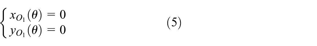
The coordinates of the rotation center of the sun gear are:
The coordinates of the rotation center of intermediate gear I are:

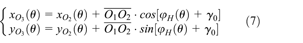
The coordinates of the rotation center of planetary gear I are:
The trajectory formed by the inflection point D1 of the transplanting arm is as follows:

β 0 denotes the initial angle between H1 of the transplanting arm and the planetary gear.
The relative motion trajectory of the cusp E of the transplanting arm is as follows:

δ 0 denotes the initial installation angle of the transplanting arm.
The absolute motion trajectory of the cusp E of the transplanting arm is as follows:

Where H denotes the plant spacing.
When performing relative motion, the horizontal velocity of the cusp E of the transplanting arm is as follows:
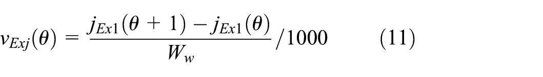
Where W w denotes the time required for the planetary carrier to rotate by 1°.
The vertical velocity of the relative motion at the tip of the transplanting arm is:

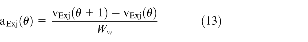
The horizontal acceleration of the relative motion at the tip of the transplanting arm is:
The vertical acceleration of the relative motion at the tip of the transplanting arm is:

Results
Parameter optimization of the WNRTM
Determination of optimization objectives
Based on agricultural machinery specifications and transplanting requirements, the optimization objectives of this study are as follows.
No interference between transplanting arms: During mechanism operation, component non-interference must be ensured. The most critical interference-prone positions—the tip of the transplanting arm and the rear shell of the transplanting arm—are selected for constraint, such that
Seedling picking angle constrained between −5° and 15°: The seedling picking angle (ξ1) is defined as the angle between the horizontal line passing through the inflection point of the seedling clamp blade and the blade’s longitudinal axis at the seedling picking position. To minimize seedling damage, this angle is constrained as: −
Seedling pushing angle constrained between 45° and 65°: The seedling pushing angle (ξ2) is defined as the angle between the longitudinal axis of the seedling push rod and the horizontal plane at the seedling pushing position. In this study, the seedling pushing angle is denoted as ξ2. To ensure optimal planting depth, verticality, and stability of seedlings, the pushing angle must adhere to the design specifications:
Angle difference constrained within 50° to 60°: The angle difference (ξ3) is defined as the absolute difference between the seedling picking angle and seedling pushing angle, with the constraint:
The transplanting arm fails to perform seedling pushing: Define S1 as the distance from the intersection point of the planted seedling line and the absolute motion trajectory to the ground. When
Gearbox ground clearance >15 mm: To maintain gearbox sealing integrity, the distance between the gearbox and the ground (denoted as S2) must be constrained. This study sets
Trajectory height >260 mm: The “bridging” phenomenon refers to the top of a previously planted seedling being inserted into the root zone of the next seedling during transplanting arm operation. By defining the trajectory height as S3, setting
Gear module >2.5: The minimum gear module is specified as

Schematic diagram of optimization target parameters: (a) non-interference of the transplanting arm, (b) seedling picking angle, (c) seedling pushing angle, (d) non-seedling-pushing state of the transplanting arm, (e) height of the gearbox from the ground, and (f) trajectory height.
Based on the aforementioned parameter optimization objectives, a “human–computer interaction” parameter optimization software was developed using the “parameter-guided” heuristic optimization algorithm and genetic algorithm. The idea of the optimization algorithm is shown in Figure 5(a), and parameter optimization is performed by utilizing objective quantification and researchers’ experience in transplanting mechanism design, the homepage of the optimization software is shown in Figure 5(b).

Optimization design software: (a) optimization algorithm flow diagram and (b) optimization software homepage.
The optimization software comprises several modules, including a graphic display area, an input parameter area, and a target area. The graphic display area can display the schematic diagram of the transplanting mechanism in real time. The input parameter area presents all parameters of the transplanting mechanism, with a fine-tuning button provided after each parameter to enable adjustment as needed. The target area displays various objectives of the transplanting mechanism in the form of progress bars, where the performance of each objective can be evaluated based on the progress bar status: blue grid bars indicate that the objective meets the seedling transplanting requirements, and a longer blue grid bar indicates a better performance of the objective.
On the premise of fully considering the agronomic requirements for rice wide–narrow row transplanting, the parameters of the transplanting mechanism were optimized using a human–computer interaction optimization method, and a set of optimal parameters was finally obtained, as listed in Table 1.
Optimal output parameter table.

Angle difference: The difference between the seedling picking angle and the seedling pushing angle; Planetary shaft rotation angle: The angle through which the planetary shaft (and also the planetary gear and transplanting arm) rotates from the seedling picking position to the seedling pushing position; Carrier rotation angle: The angle through which the planetary carrier rotates from the seedling picking position to the seedling pushing position; Carrier angle at seedling picking position: The angle of the planetary carrier when it is at the seedling picking position; Carrier angle at seedling pushing position: The angle of the planetary carrier when it is at the seedling pushing position; Height from seedling tray rotation center to ground: The vertical distance from the rotation center of the seedling tray to the ground surface.
The relative trajectory obtained based on these parameters is shown in Figure 6, and the corresponding non-circular gear parameters are shown in Table 2. The non-circular gear train is a key component of the transplanting mechanism. It converts the uniform rotation of the planet carrier into the non-uniform oscillation of the transplanting arm, which enables the transplanting arm to achieve the special trajectory and attitude required for transplanting. The non-circular gears used in this mechanism are “Bezier” gears. Their pitch curves are obtained through the Bezier curve fitting method, and the sun gear and intermediate gear are conjugate gears. As long as the parameters of the sun gear are known, the theoretical models of the sun gear and intermediate gear can be obtained using the software developed by the research team,21–24 the resulting non-circular gears are shown in Figure 7.

Optimization of transplanting mechanism parameters: (a) optimal relative motion trajectory and (b) optimize the degree of target fitting.
Non-circular gear parameters.


Non-circular gear train of the WNRTM; (a) non-circular sun gear, (b) non-circular intermediate gear, (c) non-circular planet gear, and (d) non-circular planetary gear train.
Under this parameter, the transmission ratios between the sun gear and the intermediate gear, between the intermediate gear and the planet gear, and between the sun gear and the planet gear in this mechanism are shown in Figure 8(a). Among them, the transmission ratio between the sun gear and the intermediate gear (i12) is displayed by the green line, the transmission ratio between the intermediate gear and the planet gear (i13) by the red line, and the transmission ratio between the intermediate gear and the planet gear (i23) by the blue line. The horizontal acceleration, vertical acceleration, and total acceleration of the tip of the transplanting arm of the transplanting mechanism are shown in Figure 8(b), where the blue line represents total acceleration, the red line vertical acceleration, and the green line horizontal acceleration. The horizontal velocity, vertical velocity, and total velocity of the tip of the transplanting arm of the transplanting mechanism are shown in Figure 8(c), with the blue line indicating total velocity, the red line vertical velocity, and the green line horizontal velocity. It can be seen from Figure 8 that it is precisely due to the non-uniform transmission ratios shown in Figure 8(a) that the acceleration changes in Figure 8(b) are formed, which in turn results in the velocity curves in Figure 8(c), ultimately forming the closed trajectory of “seedling picking, seedling transporting, seedling planting, and return stroke.”

Kinematic curve: (a) non-circular gear transmission ratio curve, (b) acceleration curve, and (c) velocity curve.
Determination of tilt angle for wide–narrow row configuration
In the area of Figure 1(B), the WNRTM can be simplified as shown in Figure 9. Points A, B, C, and D in the figure are seedling picking points; straight lines AA′, BB′, CC′, and DD′ represent the standard-row configuration, with A′, B′, C′, and D′ as standard-row planting points; straight lines AA″, BB″, CC″, and DD″ represent the wide–narrow row configuration, with A″, B″, C″, and D″ as wide–narrow row planting points.

Principle diagram of wide–narrow row transplanting.
Based on the parameter optimization results, the calculation formula for the lateral offset position of the planting point is first derived as:

In the formula, H represents the height difference between the seedling picking point and the planting point. The longitudinal offset distance of the planting point can then be derived as:

The distance of the planting point after offset can be derived as:

In the formula, L2 denotes the lateral distance between the seedling picking points.
The distance of the wide row during wide–narrow row transplanting can be derived as ( L6 ):

In the formula, L5 denotes the distance between adjacent rows during equal-row-spacing transplanting.
Building upon the four aforementioned calculation formulas, key transmission parameters—including the offset angle—have been derived. These parameters serve as a theoretical foundation for subsequent gearbox design and play a crucial role in enhancing transmission efficiency, meshing precision, and system stability. Building on the foundation of conventional equal-row-spacing (300 mm) rice transplantation, this study optimized the mechanism layout with a wide–narrow row configuration: 400 mm for wide rows, 200 mm for narrow rows, and an offset of 50 mm (Table 3).
Wide–narrow row transplanting configuration table.
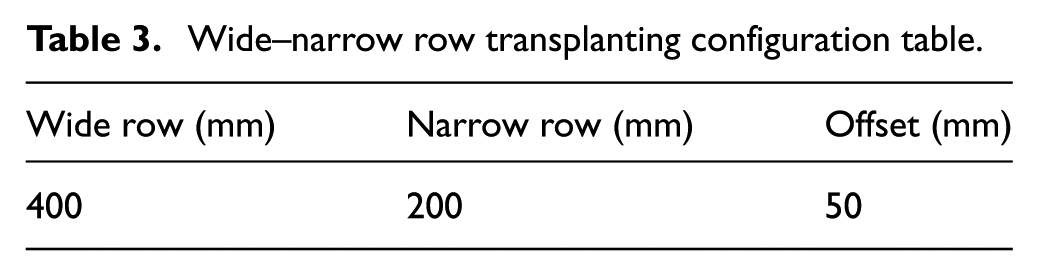
The wide-row configuration facilitates unimpeded equipment maneuverability and enhances transplanting flexibility, while the wide–narrow spacing ensures planting stability and optimal density control. The offset parameter, derived from motion trajectory analysis and operational precision requirements, optimizes seedling implantation positions to foster uniform crop growth conditions.
Using the aforementioned equations and the target wide–narrow row specifications, the calculated values are as follows:

Wide–narrow row configuration with tilt angle.
Trajectory verification and wide–narrow row transplanting experiment
Trajectory verification
Based on the optimal mechanism parameters and the determined inclination angle for wide–narrow row configuration obtained via the human–computer interaction method in the optimization software (Chapter 3.1), structural design and 3D modeling of the WNRTM were conducted in this chapter, including the transplanting mechanisms on both sides and the intermediate transmission box. Overall assembly was performed according to the initial installation position specified in the optimization software. After passing the interference check, a virtual prototype of the WNRTM was obtained, as shown in Figure 11.

Virtual prototype of WNRTM.
After the establishment of the virtual prototype, to verify the design feasibility and correctness of the inclined WNRTM based on non-circular gear trains, kinematic simulation analysis of the transplanting mechanism was first performed using ADAMS 2020 software. In ADAMS, the input rotational speed of the transplanting mechanism’s transmission box was set to 20 rpm, meaning the transplanting mechanism picks and plants seedlings 60 times/min. The simulation duration was 3 s, with a step size of 360 steps. Through kinematic simulation analysis of the entire transplanting mechanism and by adding a reference point at the tip of the transplanting arm, the transplanting trajectory of the mechanism under the inclined configuration was obtained, as shown in Figure 12.

Virtual simulation trajectory.
To verify the design correctness of the WNRTM and whether its relative trajectory is consistent with the simulation results, after completing the virtual simulation of the WNRTM, the physical prototype was fabricated, assembled, and the fully assembled transplanting mechanism was mounted on a test bench. Through tests at different rotational speeds, the transplanting performance and row spacing formed by the planting points were analyzed to comprehensively evaluate the mechanism’s performance. The assembled test bench of the transplanting mechanism is shown in Figure 13.

Transplanting mechanism test bench.
To ensure that the camera can accurately capture the motion trajectory of key points on the single-sided transplanting mechanism, the lens of the high-speed camera must be perpendicular to the gearbox of the right-side transplanting mechanism. First, an angle gauge was placed on the gearbox to obtain its offset angle. Then, the angle gauge was positioned above the high-speed camera, and the camera bracket was adjusted to ensure that the image displayed on the high-speed camera monitor was captured perpendicularly to the gearbox, as shown in Figure 14. The model of the high-speed camera used in this bench test is I-SPEED3, a microscopic high-speed camera equipped with a 1280 × 1024 pixel sensor. It features a frequency range of 24–15,000 fps, ultra-high sensitivity, a 1 μs global exposure electronic shutter, and a CDU control panel for remote device operation.
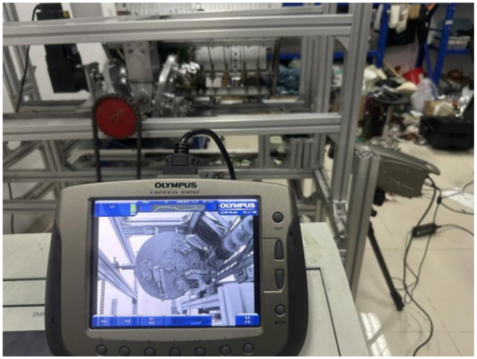
High speed camera takes pictures.
To capture the transplanting trajectory of key points, the rotational speed of the planet carrier was set to 20 r/min. A high-speed camera was used to record the full rotation process of the transplanting mechanism at this speed. After the video was saved, it was imported into the corresponding processing software of the high-speed camera, and a complete rotation process of the transplanting arm was marked in the software. The captured images of the transplanting mechanism and the trajectory marked with key points of the transplanting arm are shown in Figure 15.

Theoretical and simulation results and bench test trajectory: (a) theoretical trajectory, (b) simulation trajectory, (c) physical prototype trajectory, and (d) trajectory comparison verification.
The transplanting trajectory of the transplanting arm tip obtained via the high-speed camera is shown in Figure 15(a). The optimal trajectory corresponding to the selected parameters in the parameter optimization software is presented in Figure 15(b). The trajectory of the transplanting arm tip of the WNRTM derived from the ADAMS simulation is illustrated in Figure 15(c). These three trajectories were compared, as shown in Figure 15(d). The three trajectories are basically consistent, which verifies the correctness of the WNRTM design.
Analysis of wide–narrow row transplanting
After completing the comparative analysis of the transplanting mechanism trajectories, to further verify the wide–narrow row transplanting conditions, Adams software was used to add markers at the tips of the transplanting arms on both sides, enabling synchronous acquisition of the transplanting trajectories on both sides, as shown in Figure 16. The coordinates of seedling picking points and planting points were extracted from the obtained trajectories, and the distances between these points were measured separately. The results showed that the distance between the two seedling picking points was 304 mm, and the distance between the two planting points was 204 mm, with a deviation of 4 mm from the design values. This deviation is attributed to the fact that the tip of the transplanting arm was positioned on the outer seedling clamping piece.
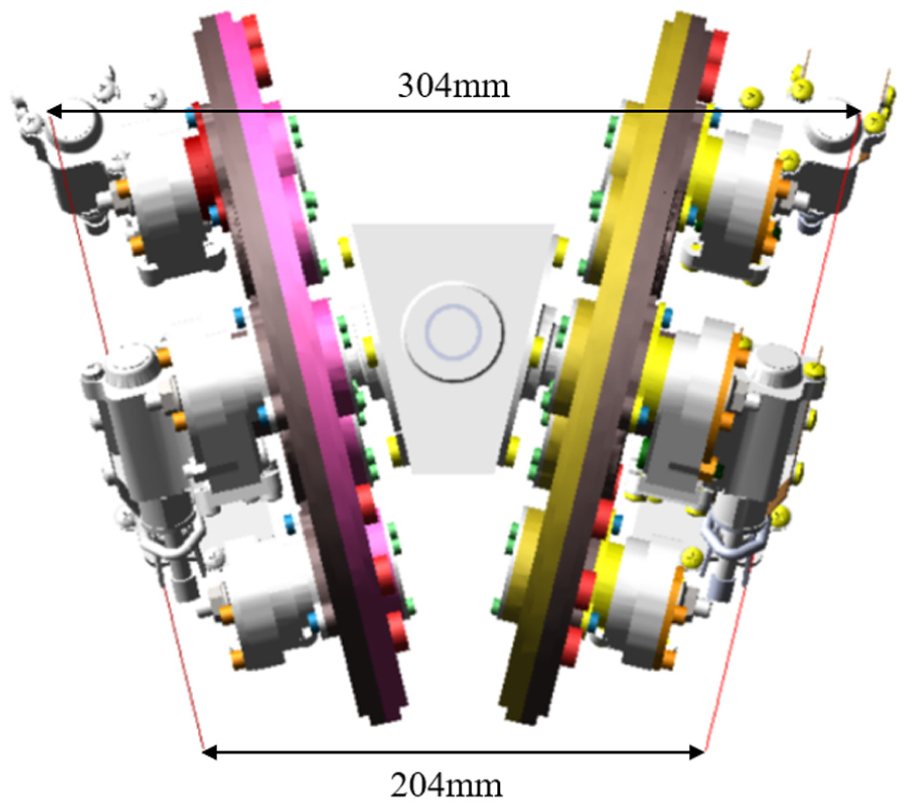
Simulation analysis of transplanting trajectory in WNRTM.
To evaluate whether the actual operational performance of the designed WNRTM meets the design criteria, a physical prototype of the WNRTM was fabricated after obtaining its simulation data in ADAMS, and wide–narrow row seedling picking tests were conducted. The seedling tray used in the tests was a standard pot seedling tray with a specification of 14 × 29, totaling 406 cells. During the tests, the seedling box was first adjusted to the initial position, and simultaneously, the transplanting mechanism was moved to the corresponding initial position via the control cabinet. The initial speed was set to 20 r/min, and the working status of the transplanting mechanism was further observed. The selected seedlings and the installation diagram of the transplanting mechanism are shown in Figure 17.

Transplanting mechanism bench seedling picking test: (a) rice seedling and (b) seedling picking test.
The focus of this study is the WNRTM, which is required to complete seedling picking in standard rows (with a 300 mm seedling picking distance, consistent with conventional pot seedling transplanters) and achieve rice potted-seedling planting under a single-side offset of 50 mm (i.e. a 100 mm total offset on both sides, forming a 200 mm operating distance). Although the design correctness of the WNRTM has been verified via ADAMS simulations, the feasibility of the design still needs to be validated through physical prototype tests. The seedling picking distance for wide rows and transplanting distance for narrow rows were measured on the test bench using a standard industrial tape measure, as shown in Figure 18. Measurements indicate that the distance between the seedling picking points on both sides of the WNRTM is 305 mm (Figure 18(a)), and the distance between the planting points on both sides is 195 mm (Figure 18(b)). These values deviate by 5 mm from the designed seedling picking distance and planting distance, respectively, which is attributed to errors in the processing and assembly of the physical prototype. However, both the planting row spacing at the planting points and the distance between the seedling picking points meet the design requirements, indicating that the designed WNRTM performs satisfactorily in wide–narrow row transplanting operations.

Analysis of wide–narrow row transplanting by the WNRTM: (a) 300 mm seedling picking distance verification and (b) narrow row transplanting distance verification.
Finally, analysis of the test results showed that the transplanting mechanism designed in this study can successfully complete the four stages: seedling picking, seedling conveying, planting, and return stroke. By comparing the relative motion trajectory in the optimization design software with the simulation results of the virtual prototype, the three are highly consistent, mutually verifying the rationality of the mechanism design. In addition, the tests indicated that the mechanism operates stably, with a low missing planting rate and minimal seedling damage, further confirming the rationality and correctness of the designed inclined rice potted-seedling WNRTM.
Conclusion
A novel inclined rice potted-seedling WNRTM was proposed. By adjusting the tilt angle of the mechanism, the transplanting unit can accomplish wide–narrow row transplanting of rice potted-seedlings, thus offering significant practical value for mechanized wide–narrow row transplanting of rice potted-seedlings.
A kinematic model of the transplanting mechanism was established, and optimization design software for the transplanting mechanism was developed based on the model. A set of optimized non-circular gear parameters was obtained through human–machine interaction optimization methods, and the configuration angle of the WNRTM was determined.
Based on the final parameters exported from the optimization software, a virtual prototype of the transplanting mechanism was developed, and kinematic simulation was performed using ADAMS to analyze the relative motion trajectory of the transplanting arm tip. The trajectory of the transplanting arm tip on the physical prototype was analyzed using high-speed cameras. The results showed that the design trajectory, virtual simulation trajectory, and physical prototype trajectory were highly consistent, thereby verifying the correctness and feasibility of the design.
Finally, a wide–narrow row transplanting bench test was conducted. The experiment showed that the designed WNRTM can pick seedlings at the 300-mm seedling gate, accomplish transplanting with 400-mm wide rows and 200-mm narrow rows, with relative error controlled within 5 mm. This meets the agronomic requirements for wide–narrow row transplanting and demonstrates practical application value.
Footnotes
Handling Editor: Chenhui Liang
Author contributions
Tingbo Xu conducts software development, algorithm optimization, and article writing. Maile Zhou provides project management and financial support. Zhaoxiang Wei, Xiao Li, Guibin Wang, Jijia He, and Shuaikang Han carried out structural design and virtual simulation.
Funding
The authors disclosed receipt of the following financial support for the research, authorship, and/or publication of this article: This study was financially supported by the Key R&D Plan of Zhenjiang City—Modern Agriculture (grant no. NY2023003), Jiangsu Province Young Scientific and Technological Talents Promotion Plan (grant no. JSTJ-2024-613), Natural Science Foundation of Jiangsu Province (grant no. BK20251906), Key Laboratory of Modern Agricultural Equipment and Technology (Jiangsu University), High-Tech Key Laboratory of Agricultural Equipment and Intelligence of Jiangsu Province. The project is also funded by the Priority Academic Program Development of Jiangsu Higher Education Institutions (grant no. PAPD 2023-87).
Declaration of conflicting interests
The authors declared no potential conflicts of interest with respect to the research, authorship, and/or publication of this article.
Data availability statement
The data presented in this study are available on request from the corresponding author. The data are not publicly available due to laboratory data privacy.