
Abstract
Among all kinds of transplanting mechanisms which are the important parts of transplanters, the planetary gear train transplanting mechanism is widely used for its excellent transmission performance, but it is difficult to design the gear pitch curves and structural parameters according to the trajectory and pose requirements of transplanting. The current design method of the non-circular planetary gear train transplanting mechanism cannot ensure the precise position and posture in the crucial points of transplanting trajectory, nor take both the anticipated trajectory and the smoothness of the gear pitch curves into account, it will only get one solution which is available for mechanism design. In order to solve those problems, the non-circular planetary gear train transplanting mechanism is analyzed as a combination of the bar-group and gear train system. According to the transplanting requirements, three points with precise position and posture which called pose points in the trajectory are given to obtain the solution domain of the parameters of bar-group, and then trajectory shape control points are inlet to design the desired shape of the transplanting trajectory and obtain the transmission ratio curve which can be used to get the gear pitch curve. The most suitable parameters of bar-group in solution domain are selected based on the smoothness of the gear pitch curves. This article establishes three-dimensional model of the mechanism and utilizes the ADAMS to carry out a motion simulation; all simulation results are consistent with theoretical design results, which confirm that the design method based on prescribed pose points and trajectory control points is adequate for the transplanting mechanism. With the proposed method, the selectivity of the mechanism’s parameters solution is increased, and transmission performance benefits from the integrated design of trajectory control and the smoothness of the pitch curves.
Introduction
The transplanting mechanism, which is the important part of the transplanter, has developed three stages including the crank–slider mechanism, the crank–rocker mechanism, and the planetary gear train mechanism, which is becoming more and more perfect.1–3
The crank–slider mechanism can easily achieve a special trajectory; its design is flexible and convenient, but its structure is complex, efficiency low, and cost high; it is the primary development stage of the transplanting mechanism. 4 The efficiency of crank–rocker mechanism which can only be equipped with single transplanting component is not high, and its optimal design is not difficult; it is hard to increase transplanting efficiency.5,6 Meanwhile, the damage to the seedlings during transplanting process is more serious due to the greater vibrations and shocks. The planetary gear train mechanism has many advantages: simple structure, low cost, high efficiency, smooth transmission, and the strongest competiveness.7,8
Many scholars had researched on the design method of planetary gear transplanting mechanism. Zhou Maile used Bezier curve fitting technology to design the non-circular gear pitch curves. By setting the control points of the gear pitch curves, he designed the Bezier planetary gear train system suitable for rice seedlings transplanting mechanism. 9 Zhao Xiong analyzed the requirements of pot seedling transplanting and studied the generation principle of eagle trajectory; he utilized multi-objective optimization design method to design a non-circular planetary gear train transplanting mechanism. Given the transmission ratio curve control points, he established the objective function of the mechanism optimization, and the optimization of multiple objectives was achieved by searching for the best value of control points. This design method is intuitive and easy to model, but it can obtain only one feasible solution, and it cannot get the satisfactory solution for the complex problem. 10 After analyzing the work requirements of rice seedling transplanting, Bae and Yang used reverse design method of parameters to design a non-circular planetary gear train system. Three prescribed trajectories were designed to reverse the transmission ratio curve, so as to design the non-circular planetary gear train system. The goal of this method to obtain desired trajectories is clear, but it is not sure whether the execution component will meet the requirements or not in the crucial points in the initial design. 11
Two basic category can be concluded from the current design method of the gear train transplanting mechanism, one is the optimization design method, the trajectory is optimized based on the optimization design of gear pitch curve or the gear train transmission ratio, the other is the reverse design method, trajectory were set as known condition, so the transmission ratio of the planetary gear train can be obtained. There are three deficiencies in these design methods above. The first one is that it is not able to achieve precise pose requirements at crucial points, the second one is that it is not easy to adjust the trajectory flexibly to meet the expectation or ensure the smoothness of gear pitch curves, and the third is that only one set of the parameters of mechanism will be obtained; it is difficult to get a wide range of solution domain for selecting different parameters of mechanism.12,13
This article considers the non-circular planetary gear train mechanism as the combination of bar-group and gear train and aims to develop a new efficient design method. Given three points with precise position and posture according to the transplanting requirements, the solution domain of the parameters of bar-group can be obtained, and then trajectory shape control points are introduced to design a expected trajectory. Based on the solution domain and trajectory shape control points, the transmission ratio will be obtained which is used to design gear pitch curves. Each solution in the solution domain can get a transmission ratio curve which means various planetary gear train mechanisms can be designed. Finally, the most suitable parameters of the bar-group will be selected from the solution domain based on the smoothness of gear pitch curves. The validity of the method proposed is illustrated by three examples. Furthermore, a three-dimensional (3D) model of mechanism is established; the correctness of the method is verified by a kinematic simulation.
Planetary gear train design with precise pose points and trajectory optimization
Establishment of the solution domain of bar-group with three precise pose points
The crank and coupler of the linkage mechanism can form a bar-group, which is shown in Figure 1.

Bar-group movement analysis.
A0
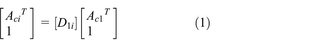
D1i is the displacement matrix, and it can be directly obtained with the general rigid-body displacement matrix

Matrix elements in D1i are the following

Among the elements,

Equation (4) can be obtained by combining equations (2) and (3)

In equation (4)

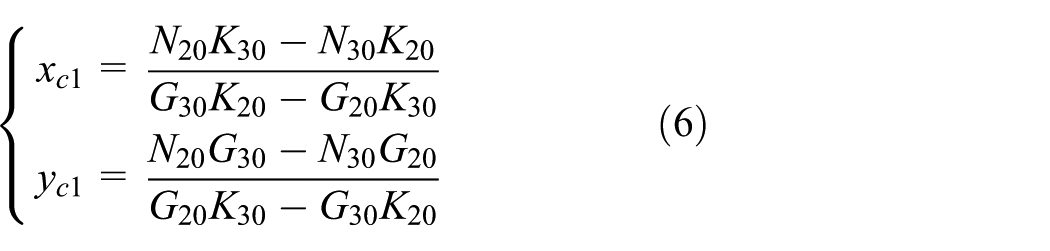
Given three pose points P1, P2, and P3, the azimuth angles in these three points are θ1, θ2, and θ3. Given the coordinates

In equation (5)
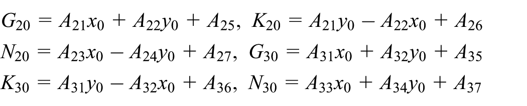
Therefore, the coordinate values of the movable hinge point Ac1 can be calculated by equation (6)
There is no restriction on the coordinate value of A0, any point on the plane can be used as A0, and the movable hinge point will also fill the entire space. Without additional constraints, the solution domain of the parameters of bar-group will fill the entire space.14–17
Solution domain of the parameters of bar-group
The planet carrier of the planetary gear train transplanting mechanism is considered as a crank and the seedling pick-up arm as a coupler, so the bar-group model of the transplanting mechanism can be obtained. To control the overall size of the mechanism, the length of the planet carrier should be set in advance; it is also a constraint for solving the solution domain of the parameters of bar-group. In this case, the movable hinge point will be limited in a certain range of spaces. According to the transplanting requirements, three pose points can be calculated and the rough trajectory is designed, which are shown in Figure 2.

Bar–group model of transplanting mechanism.
The length of the planet carrier A0Ac1 is r; there is

Combining equations (6) and (7) to obtain the coordinate values of the fixed hinge point A0

When the values of x0 continuously changes in a certain length of interval with a proper step length, a set of values of y0 can be calculated using the numerical algorithm, so the coordinate values of the fixed hinge point A0 can be fit into a solution curve. Then the solution curve of the movable hinge point Ac1

The value of ψ equals the angle between the coupler and the horizontal line minus the azimuth angle of the coupler. Limiting the value of r in a length of interval, the solution curves of the two hinge points will form a range of areas. The solution domain will be filtered and reduced initially by limiting the coordinate values of A0
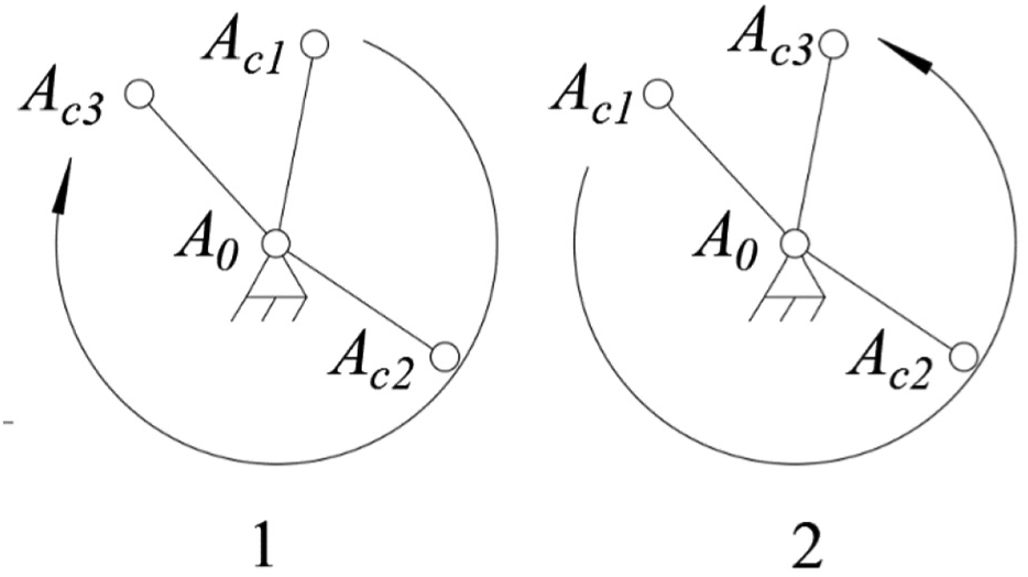
Two situations of the position of the moving hinge point.
Removing the solutions those do not meet the above conditions, the solution domain of bar–group parameters will be obtained.
Optimization design of gear pitch curves and parameters of transplanting mechanism
The trajectory formed by the end point of the seedling pick-up arm is an important factor to meet the transplanting requirements. The number of pose points is too small to design a trajectory with desired shape, so it is necessary to add some points to control the shape of trajectory which can also control the movement range of the seedling pick-up arm so as to the ensure that the mechanism does not interfere with other parts.
The trajectory is generated in a direction which is shown in Figure 4. The trajectory is divided into three segments taking the pose points as the boundary. Points are appropriately added in each segment of trajectory according to the distribution of the pose points and the complexity of the expected trajectory. Two trajectory shape control points E1 and E2 are added between P1 and P2.
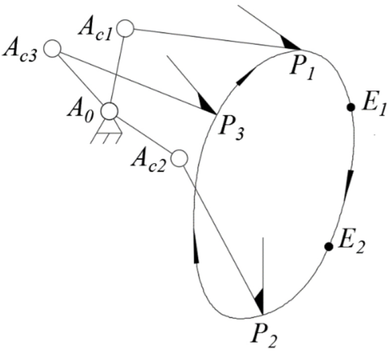
Schematic diagram of the trajectory.
After adding trajectory shape control points, it is necessary to check whether there is any movement defect with the bar-group. When the bar-group passes through a trajectory shape control point, there are two situations exist as shown in Figure 5:

Two situations at the trajectory shape control point.
There are two criteria to judge whether the bar-group has movement defect:
When the bar-group passes through the prescribed poses points and trajectory shape control points in sequence, the rotation direction of the planet carrier must be consistent. For example, the trajectory direction is Pj–Ei–Pk shown in Figure 3, it is clockwise, so it is going to be right while the moving direction of the movable hinge point is Acj–Ace–Ack instead of
The rotation angle of the seedling pick-up arm relative to the planet carrier keeps increasing or decreasing, keeping monotonicity. As shown in Figure 6, there were two feasible situations of the bar-group position in the trajectory shape control point Ei which meet planet carrier’s rotation direction condition; in this case, the rotation angle of the seedling pick-up arm relative to the planet carrier should be taken into account.

Two situations of rotation angles at the trajectory shape control points.
The trajectory direction is Pj–Ei–Pk and the planet carrier rotates clockwise. The rotation angle of the seedling pick-up arm relative to the planet carrier keeps increasing while it changes in the way of Фj–Фe–Фk rather than
In the above, only the direction of P-E-P was discussed. The other three cases are P-E-E, E-E-E, and E-E-P. These criteria are also suitable to check the other three cases if there are some movement defects in the bar-group.
After eliminating the defect of the bar-group passing through each control point, the value of αi which is the angle between the planet carrier and the horizontal plane and the value of βi which is the angle between the seedling pick-up arm and the horizontal plane can be calculated when the bar-group passes through each pose point and trajectory shape control point. Utilizing the angle α i and β i , the angle ϕ ri and ϕ li which are the rotation angles of the planet carrier and seedling pick-up arm can be calculated

For example, in Figure 4, there are five sets of Фri and Фli according to the pose and control points, and they are sorted along the trajectory direction. Mathematical methods are utilized to fit the curve of the rotation angle relationship between the planet carrier and the seedling pick-up arm. 18 To make the derivative of the beginning of the curve equals to the end, extending the five groups of data to three cycles, and select angle curve of the middle one cycle which is shown in Figure 7.

Schematic diagram of fitting a three-cycle rotation angle curve.
After fitting the relative angle curve between the planet carrier and the seedling pick-up arm, the total transmission ratio of the planetary gear train of the transplanting mechanism can be calculated, and the whole gear train system can be designed. The process of design and calculation are the same as the reverse design method of parameters of the non-circular planetary gear train, which has been detailed in the previous reference. 19
After obtaining the pitch curves, the smoothness of the pitch curve is used as a criterion, and select the appropriate solution from the solution domain to optimize the mechanism.
The first step is to verify the convexity and concaveness of the pitch curve. The polar coordinates of the non-circular gear pitch curve can be expressed in the formula of R = R(φ), and equation (11) is used to calculate the radius of curvature at each point on the pitch curve
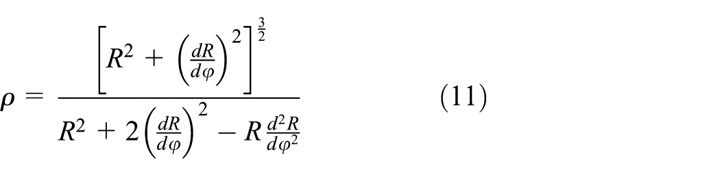
In the formula, R is the length of the radius vector, and φ is the included angle between the radius vector and the horizontal plane. Every point in the pitch curve of circle gear has the same radius of curvature which is just the radius of circle gear; for non-circle gear, it is different and complex to calculate the radius of curvature, so equation (11) is used.
If ρ is positive, the gear pitch curve is convex; otherwise, it is concave.
Convex gear pitch curve can use toothed tools or gear hobs to generate tooth profile; it is more convenient than the concave gear pitch curve, so the first step of inspection is to check whether the pitch curves of the planetary gear train system are all convex; if so, they do not need to be screened; otherwise, the second step is performed.
In the second step, when gear pitch curves calculated by the whole solution domain cannot meet the conditions in the first step, the concave gear pitch curves are considered to use. An excessively concave gear pitch curve cannot generate the tooth profile, so the minimum curvature radius of the concave gear pitch curve must not be too small. Based on this, the curvature radius of the gear pitch curve in the gear train is calculated, and ρmin which mean its minimum value shows the concave degree of this group of gear pitch curves calculated by one solution. The ρmin of all solutions in the solution domain shall be calculated and the solution with the largest ρmin shall be selected as the optimal solution.
In the third step, if the gear pitch curves obtained by optimal solution cannot generate the tooth profile, the poses points remain unchanged, the trajectory shape control points should be reset, and the solution domain shall be calculated again. To summarize the design method of this article, the overall process is shown in Figure 8.

Design process.
Design example
Seedlings transplanting can be divided into pot seedlings transplanting and blanket seedlings transplanting; furthermore, the pot seedlings transplanting has two different types: clamping seedlings type and clamping pot type. Following are the examples of the three kinds of transplanting stated above. MATLAB is utilized to design a software with graphical user interface.
First example is the blanket seedlings transplanting, its work trajectory is similar to the letter “D”, three pose points of this trajectory are shown in Table 1.
Three precise poses points of the blanket seedlings transplanting.

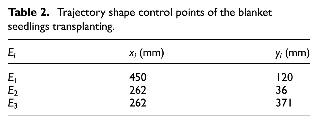
r is the length of the planetary carrier which value is limited to 110mm∼ 130mm, and x0 is x-coordinate of the fixed hinge point A0 which value is limited to 140mm∼ 160mm and the trajectory shape control points are shown in Table 2.
Trajectory shape control points of the blanket seedlings transplanting.
The most appropriate solution selected from the solution domain of bar–group parameters is shown in Table 3.
Bar–group parameters of the blanket seedlings transplanting.

The final trajectory is shown in Figure 9. The trajectory direction is clockwise. P1 is close to P2, so there is no other control point between them. There is some distance between P2 and P3, but the trajectory between them is simple, so only one control point is needed. The trajectory between P3 and P1 is the most complex and the two points are also far away from each other, so two control points are added. In the following two examples, control points are added according to the same principle.

Trajectory of blanket seedlings transplanting.
The corresponding non-circular gear pitch curves in the planetary gear train are shown in Figure 10.

Gear pitch curves of blanket seedlings transplanting.
The second one is the clamping seedlings type of the pot seedlings transplanting; three pose points on the transplanting trajectory are shown in Table 4.
Three precise poses points of the clamping seedlings transplanting.

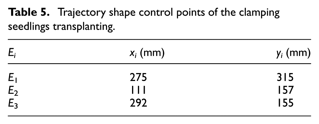
The value of r is limited to 75–100 mm, and the value of x0 is limited to 180–220 mm, and the trajectory shape control points are shown in Table 5.
Trajectory shape control points of the clamping seedlings transplanting.
The most appropriate solution selected from the solution domain of bar–group parameters is shown in Table 6.
Bar–group parameters of the clamping seedlings transplanting.

The final trajectory is shown in Figure 11. The direction of the trajectory is counterclockwise.

Trajectory of clamping seedlings transplanting.
The corresponding non-circular gear pitch curves in the planetary gear train are shown in Figure 12.

Gear pitch curves of clamping seedlings transplanting.
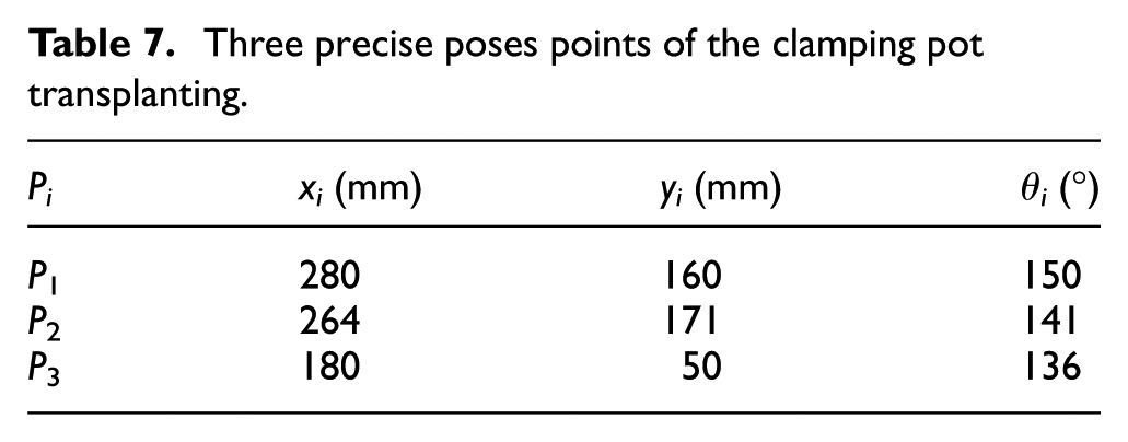
The third one is the clamping pot type of the pot seedlings transplanting; three pose points on the transplanting trajectory are shown in Table 7.
Three precise poses points of the clamping pot transplanting.
The value of r is limited to 65–75 mm, and x0 is limited to 90–110 mm, and the trajectory shape control points are shown in Table 8.
Trajectory shape control points of the clamping pot transplanting.

The most appropriate solution selected from the solution domain of bar–group parameters is shown in Table 9.
Bar–group parameters of the clamping pot transplanting.

The final trajectory is shown in Figure 13. The trajectory direction is counterclockwise.

Trajectory of the clamping pot transplanting.
The corresponding non-circular gear pitch curves in the planetary gear train are shown in Figure 14.
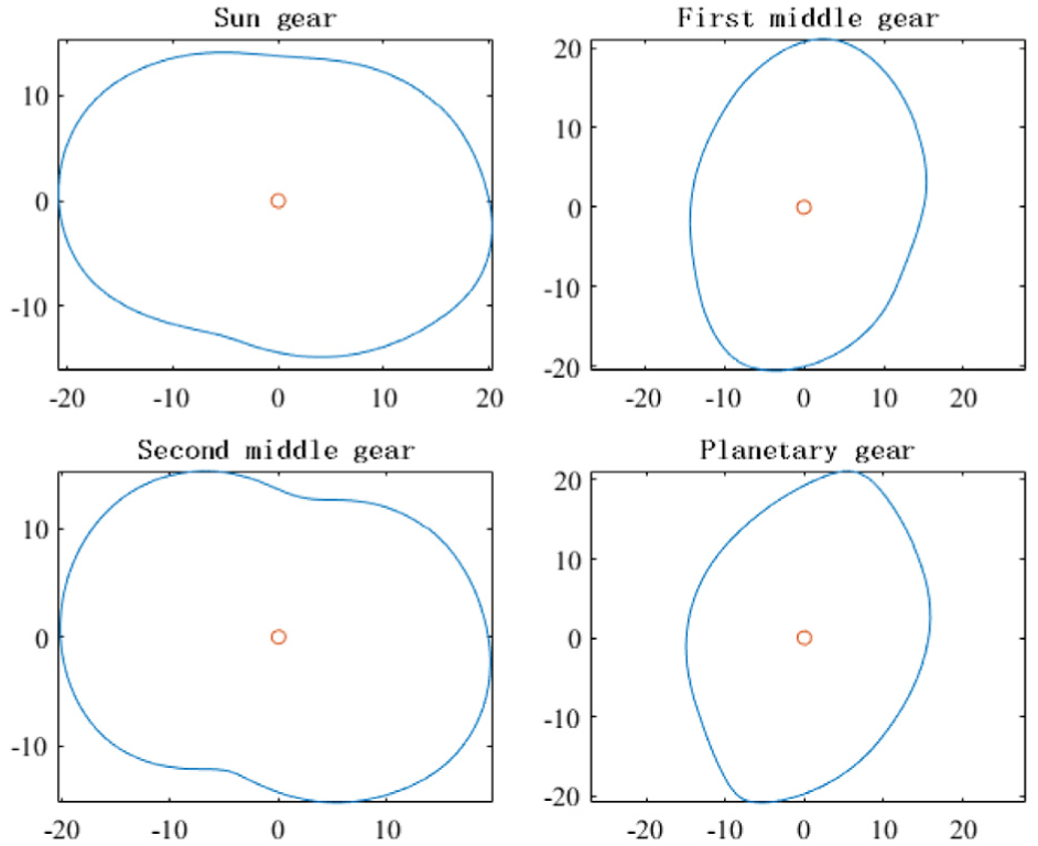
Gear pitch curves of the clamping pot transplanting.
Simulation and verification
The third example was selected to design three-dimensional model and Adams software was utilized to perform a motion simulation and verification. According to the pitch curves shown in Figure 14, the tooth profile was created, and the non-circular gear 3D model was created using AutoCAD and SolidWorks; the installation diagram is shown in Figure 15.

Gear-train installation diagram.
According to the solution domain of the bar-group parameters, the planet carrier and seedlings pick-up arm were designed, and a three-dimensional model was established, then the model was imported into Adams for simulation; the simulation trajectory is shown in Figure 16.

Simulation trajectory.
This trajectory was compared with the trajectory taken from Figure 13, their shapes are the same, and then compared the data of the three precise pose points which are shown in Table 10.
Comparison of pose points data.

Results and discussion
First, the precise pose points in each example above were all determined by the work requirements. P1 is the seedling picking up point, the seedling pick-up arm takes the seedling away from seedling box and moves a distance after picking up seedlings until arrives in point P2, and P3 is the seedling pushing point. The precise pose points should be changed according to different situations.
Second, except the well-designed trajectory of the blanket seedlings transplanting (Figure 9), the trajectory of the clamping seedlings type transplanting in Figure 11 and the trajectory of the clamping pot type transplanting in Figure 13 are not satisfactory; the lowest points of both trajectories are not the ideal position to drop off seedling which are supposed to be P3. The distance between the lowest point and P3 is 18.81mm in Figure 11 and 6.86mm in Figure 13. It was not supposed to happen in the theoretical design. The reason was that the given trajectory shape control points were improperly selected. For example, after changing the position of E3, a more ideal trajectory curve was generated, which is shown in Figure 17. However, the improper choice of control points can also lead to bad results, because the role of the pose points and shape control points is to calculate the transmission ratio curves, which determines the final gear pitch curve. As shown in Figure 18, after changing the E3, the gear pitch curves become worse, which means they are concave seriously, once this happens, it is difficult to generate tooth profiles and cannot ensure the smoothness of the transmission or the strength of the parts. Therefore, if the trajectory shape control points (like E3) get changed, it is necessary to check the gear pitch curves whether them are usable.

New trajectory after changing the parameters of E3.

New gear pitch curves after changing the parameters of E3.
Third, as shown in Table 10, the theoretical design results have subtle errors with the results obtained from the simulation. P1 was the initial installation position, and its theoretical values were consistent with the simulation values. P2 and P3 were not exactly the same, and there were subtle errors because the tooth profile generated is not so accurate which affected the simulation, but the difference is little and it can be acceptable.
Conclusion
The article analyzed the non-circular planetary gear train transplanting mechanism in the perspective of the combination of bar-group and gear train. Given three points with precise position and posture according to the transplanting requirements, the solution domain of the parameters of bar-group can be obtained; then trajectory shape control points were introduced to design the desired shape of the whole transplanting trajectory. In combination with the solution domain and control points, transmission ratio curves were obtained which were used to design non-circular gear pitch curves. Finally, the most suitable solution was selected from the solutions domain based on smoothness of the gear pitch curves. Three design examples listed in the article and the simulation results prove that the method was feasible and suitable for general transplanting tasks.
The establishment of three precise pose points ensured that the position and posture of the seedlings pick-up arm at the crucial points can meet the transplanting requirements in the pre-design stage, which also achieved the requirements of multi-object’s precise pose in engineering. By adjusting the trajectory shape control points, the final trajectory can be adjusted flexibly to ensure that the mechanism will move within a reasonable space. When the final gear pitch curve is not ideal, it can also be corrected quickly by adjusting the trajectory curve. There are multiple solutions in the solution domain and each solution corresponds to a kind of planetary gear train mechanism size. The solution domain provides more choices for selecting the transplanting mechanism parameters compared to the existing design methods which can only get one solution.
Footnotes
Acknowledgements
The authors thank the editors and the anonymous reviewers whose constructive comments have notably contributed to the improved quality and clarity of this article.
Handling Editor: Jose Ramon Serrano
Declaration of conflicting interests
The author(s) declared no potential conflicts of interest with respect to the research, authorship, and/or publication of this article.
Funding
The author(s) disclosed receipt of the following financial support for the research, authorship, and/or publication of this article: This work was supported by the National Key Research and Development Program of China (grant number 2017YFD0700800);National Natural Science Foundation of China (grant numbers 51775512,51575496); the Natural Science Foundation of Zhejiang Province (grant number LZ16E050003); Basic public welfare research projects of Zhejiang Province(grant number LGN19E050002); The 521 Talent Project of Zhejiang Sci-Tech University.