
Abstract
Non-circular crossed gear can be regarded as the general form of the single stage gear, which can be converted into hypoid gearing, non-circular bevel gearing, non-circular external gearing, and non-circular internal gearing with specific parameters. This paper established its mathematical model, deduced equation of its axode, and put forward a new method of tooth profile generation with introduction of relative velocity. In term of the theory above, the 3D model of a pair of conjugated gears was built, and its output angular velocity was obtained in analysis of ADAMS. Finally, the physical prototype of the gearing was developed and output angular velocity was measured as well. Both the simulation and measurement results show the motion is in good condition, which confirms the correctness of the theory and algorithm.
Introduction
In the study of non-circular gear transmission, current research mainly focuses on non-circular cylindrical gear and non-circular bevel gear. Non-circular cylindrical gears transfer the variable speed ratio between two parallel shafts, internal meshing or external meshing, and is widely used in function generator,1,2 gear pump, 3 and some specific movement devices4–7; While non-circular bevel gears transfer variable speed ratio between two intersecting shafts with compact structure, high transmission efficiency 8 and is widely used in bevel gear pump, 9 variable ratio limited-slip differential. 10 Furthermore, hypoid gear is the spatial crossed axes gear, neither parallel nor intersectional, 11 but its gear ratio is constant. 12
In conclusion, the general situation of the gear forms above is non-circular crossed gear which can be regarded as the most complex and general situation of single stage fixed-shaft gear. With special parameters, it corresponds to different gear form: it is hypoid gear transmission with constant transmission ratio. It is non-circular bevel gearing with zero wheelbase. With zero shaft angle, it converts into external non-circular gearing, while the internal non-circular gearing with 180° shaft angle. As a consequence, the type of gearing research focuses on the generality of all form of gears above, namely, a mathematical model can include all forms of gearing, it will provide great convenience for design, especially for the development of design software.
This form of gear can realize spatial crossed shafts nonlinear transmission with some advantages of hypoid gear (compact structure, high bearing capacity). In some special occasions, it will be widely used.
This paper embarked from the basic principle of spatial mesh, combined with the non-circular gear radio function, established the mathematical model of non-circular crossed gear. Firstly, this paper gave the calculation methods of axode and generates method of tooth profile. On this basis, a pair of non-circular crossed gears was designed with 90° shaft angle and 10 mm axis base. After finite element analysis for the contact tooth profiles, the physical prototype of the gearing was developed. Both the simulation in ADAMS and the measurement of the physical prototype proved the correctness of the mathematical model.
The generalized pitch surface – axode
Figure 1 shows the coordinate system used to the analysis of spatial mesh.

Spatial coordinate system of spatial mesh.
Coordinate system
The coordinate transformation matrix of coordinate system

Then, the coordinate transformation matrix of coordinate system

The coordinate transformation matrix of coordinate system

Axis
Here starting from the basic relation of non-circular gear transmission, the matrix expression of screw motion parameters will be deduced again.
Suppose the gear transmission ratio is a function of the rotation angle of drive gear.

Where,
Define that, the angular velocity of drive gear1 under the frame S is as follows:

Then, the angular velocity of driven Gear 2 is as follows:

Therefore, the angular velocity of instantaneous axis is:

Thus, the direction vector of the instantaneous axis (a unit vector of the velocity vector):

Where
The position of axis

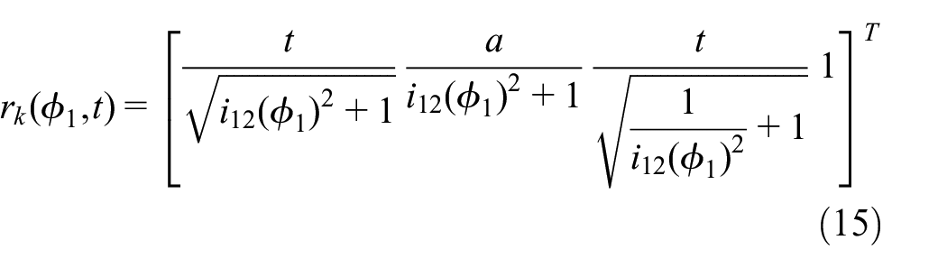
Thus, arbitrary point on the axis

Where
The axode of gear can be obtained through transforming the coordinate values of axis-k under the coordinate system S into corresponding gear coordinate system with corresponding transformation matrix respectively. 16
Thus, the axode of Gear 1 is:

The axode of Gear 2 is

Where,

Here, a general condition – a pair of two crossed vertical shaft gear was derived, that is, the spatial included angle


The surface represented by equation (16) is the same with the pitch surface of non-circular bevel gear while a = 0.
18
Furthermore, the surface of equations (11) and (12) agrees with the pitch surface of non-circular external gear while
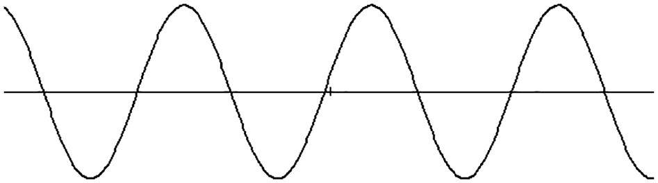
Now, a transmission ratio function is provided as follows for an example (shown in Figure 2):


Gear ratio function.
In term of equation (13), a pair of non-circular gear meet the pitch curve closed condition so that it can be used in continuous rotation, thus

Plug equation (18) into equations (16) and (17), then wheelbase

The axode of non-circular crossed gear.
In all, the non-circular crossed gear is the general situation of the single stage gear transmission, in different conditions, it can turn into hypoid gearing (gear ratio is constant), the non-circular bevel gearing (wheelbase is 0), non-circular external gearing (included angle is
Tooth profile generated by rack cutter
The screw pitch of axode is as follows 15 :

It also proves the existence of the generating wheel and deduces its parameters, therefore it easy to know that the generating surface is screw surface in the crossed axis position discussed above, when constant transmission ratio, the generating surface is linear screw surface. In fact, only the screw pitch to 0, the tooth profile of generating wheel can be structured conveniently.
According to equation (20), whether the non-circular bevel gear (a = 0), the non-circular external gear (
For the crossed gear, its screw pitch is no longer zero, thus, building tooth profile on the screw surface is very difficult, especially for non-circular gear transmission, its screw pitch is varying, building profile in general method is almost impossible. Therefore, a new method must be sought.
Here, the tooth surface is derived no longer from the generating surface, but by the counterpart rack and the principle of relative velocity, 22 the same with the approach that formed spatial helical gear tooth profile.
Figure 4 shows the speed relations of counterpart rack and non-circular gear.

If the tool rack moves along the direction of common velocity vector

The counterpart rack and gear speed relations.
According to the principle above, if there is a counterpart rack which is fixed on a certain radius


Comprehensive equations (21), (22), (23) are common velocity:

The velocity of axode:
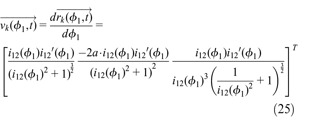
The velocity of counterpart rack is the resultant velocity of equations (23) and (24):

The unit of this velocity is:

Established a reference frame

According to vector coordinate transformation relation [14], then

Where, the subscript presents the vector of each coordinate components.
As well, establish a coordinate system
The coordinate transformation matrix:

where:

The module of counterpart rack:
Where,
Assumes that the profile of rack is
Thus, envelope equation of the tooth profile of Gear 1 is:

In the same way, envelope equation of the tooth profile of Gear 2 is:

Put all the volume in the equations (33) and (34), the specific expression of the envelope equation can be obtained. The geometric figure of this equation is an enveloped surface cluster, while its boundary is the tooth profile of each gear. 23 Therefore, the tooth profile can be gained by solving the envelope equation using the meshing principle or numerical method. 24
From the derivation above, it is knowable, the starting position, direction, modulus is varying in different radius
Need to point out that only when the axode of non-circular Gear 1 and Gear 2 is convex, the tooth profile can be gained by generating rack, 25 if axode is concave surface, a generating gear must be built, the methods of this situation will be presented in subsequent papers.
Geometry design and analysis
Figure 5 shows end shapes of the generating rack with sine tooth profile curve. In combination with the transmission ratio function provided by equation (17) and the wheelbase above, put the equation of rack profile into equations (32) and (33), the envelope equation of gear is gained. The envelope curve clusters of Gear 1 and Gear 2 are shown respectively in Figures 6 and 7 where radius
The end shapes of the generating rack.

The envelope curve of Gear 1 where t = 35.

The envelope curve of Gear 2 where t = 35.
Radius

3D model of Gear 1.

3D model of Gear 2.

The gearing assembly in PROE.
The transient structural solution module is selected for solution. The steel with elastic modulus of 210 GPa and Poisson’s ratio of 0.3 is selected for analysis. SOLID187 is used to mesh the model. SOLID187 element is a high-order 3-D 10 node element with quadratic displacement characteristics, which has the capacity of large deformation and large strain. The model is finally composed of 654,090 nodes and 452,585 elements. Select the tooth surface that contacts as the contact surface, set the contact type as friction, and select the friction coefficient as 0.1 according to the gear manual. Set the driving gear tooth surface as the master (CONTACT174 elements) and the driven gear tooth surface as the slave (TARGE170 elements). The rotary connection is arranged on the inner hole surface of the driving wheel and the driven wheel. The set speed of the driving wheel is 0.5 rad/s, and the set resistance torque load of the driven wheel is 10 Nm. The analysis time is set as 1 s, and the substep is set as 30 to ensure that the gear completes a complete meshing cycle from the root to the top.
Figure 11 shows the finite element model after mesh generation. According to the contact stress concentration area and calculation efficiency, dense meshes are used in the gear contact area, while other areas are relatively sparse. Figures 12 and 13 show the contact stress nephogram of Gear 1 and Gear 2. The bearing contact was stabilized, and the calculation results show that the maximum contact stress values of the gear are 311.49 and 329.96 MPa, respectively, which is far less than the yield strength of the gear material.
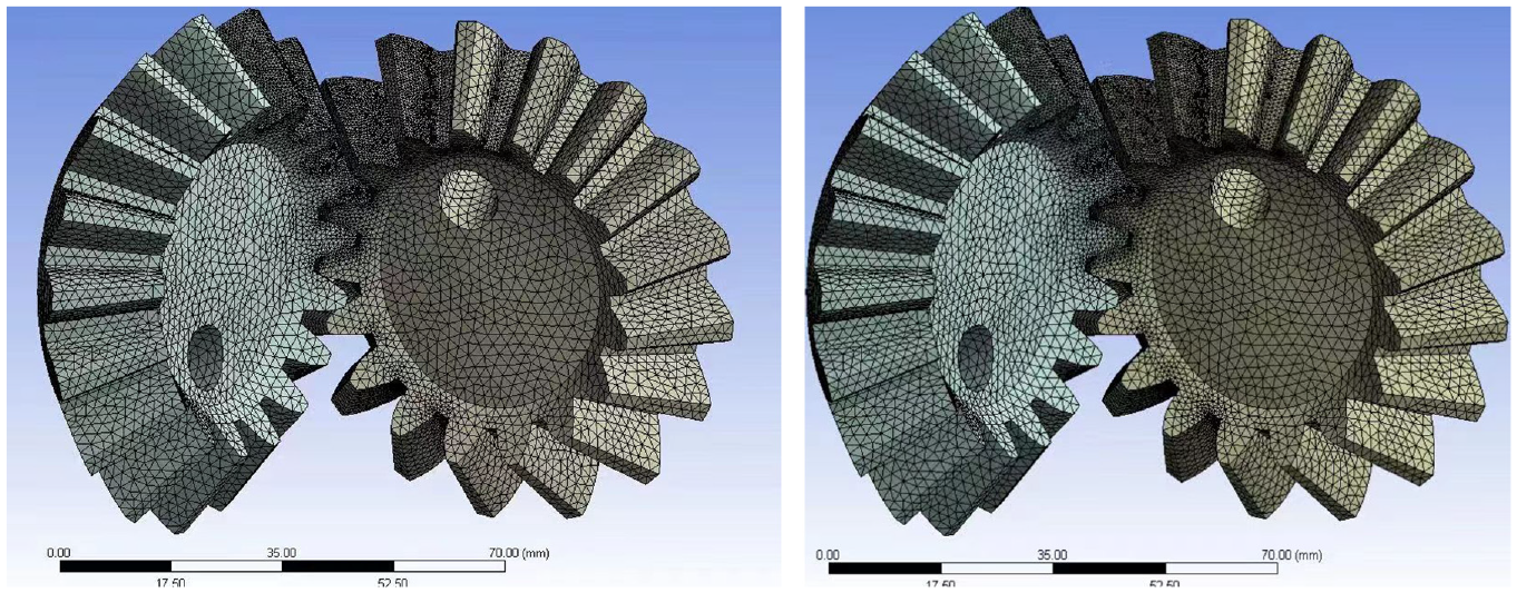
Mesh devision.

Stress nephogram of Gear 1.

Stress nephogram of Gear 2.
Import the model into ADAMS, define material properties of each solid: density of

Set parameters and constraints in ADAMS.

The angle velocity gained by ADAMS analysis.
On the other hand, the velocity of Gear 2 can be obtained in term of equation (4), thus

Value of

The velocity of driven gear in theory.
Here, following views are put forward by the comparison of simulation and theoretical calculation:
(1) Simulation completed successfully confirms that the two gears have no interference (or a very small size interference) in the process of rigid motion, namely, the tooth profile of two gears meet spatial conjugate meshing and the correctness of the mathematical model above.
(2) By comparing the speed response in Figure 15 and the velocity shown in Figure 16, it easy to found that the trend of speed response is in keeping with driven gear by theoretical calculation and the scalar of angle velocity obtained by ADAMS. It means gear ratio fits the transmission ratio function basically, however there are some certain fluctuations, it is reasonable though the analysis in the view of dynamics, such as the meshing impact, contact ratio, variable acceleration, the numerical error, ADAMS processing method of contact problems, etc. 12
Development of the prototype
According to the interpretation above, this type of gear can’t be generated by standard tool rack for its varied screw pitch of the tooth profile. Thus, gears were fabricated by 5 axis NC machine in term of the data of the 3D model constructed above. Then the prototype containing shafts and bearings assembly was developed. Figure 17 shows the global perspective of the prototype; Figures 18 and 19 respectively show the assembly of Gear 1 and Gear 2 in the prototype, while Figure 20 shows the conjugate meshing of the gears. To detect transmission performance of the prototype, an encoder was placed on driven shaft as it is shown in Figure 21. Finally, the angular velocity of driven gear was measured and it is shown in Figure 22. It meets the theoretical curve shown in Figure 16 well, it means the motion and mesh of the prototype is in good condition, so that it confirms the correctness of the design and algorithm above again.

Global perspective of the prototype.

Assembly of Gear 1.

Assembly of Gear 2.

The conjugate meshing of the gears.

Angular measurement by encoder.

The measured results of driven gear.
Conclusions
(1) Demonstrate the crossed non-circular gear is the general form of single stage transmission, namely, under the condition of different parameters, it can be converted into different gearing that has been studied widely (non-circular internal gear, non-circular external gear, non-circular bevel gear, and hypoid gear).
(2) The mathematical model of non-circular crossed gear is established: deduce the axode of drive gear and driven gear respectively, elucidate the approach to gain the tooth profile in term of instantaneous relative velocity of generator and each gear, derivate the envelope equation of each gear’s tooth profile in term of the generating rack tool.
(3) Build the 3D-model of each gear, take an example of sinusoidal generating tool rack, in term of the mathematical model above, show the design process through computer graphics. Then, establish the virtual prototype of gearing and gain the angular velocity curve in the view of rigid body dynamics in ADAMS, which meets the curve theoretical calculation well, thus prove the validity of the design method vias computing simulation.
(4) Developed a physical prototype of non-circular crossed non-circular gearing fabricated by 5 axis NC machine. The measured curve of angular velocity shows that the motion and mesh of the prototype are in good condition. It shows that the gear can be fabricated and gearing can realize.
Footnotes
Handling Editor: Chenhui Liang
Declaration of conflicting interests
The author(s) declared no potential conflicts of interest with respect to the research, authorship, and/or publication of this article.
Funding
The author(s) disclosed receipt of the following financial support for the research, authorship, and/or publication of this article: Guangxi Provincial Science and Technology Major Special Project: R&D and Industrialization of High-Efficiency Dual Drive Axles for National Six Heavy Duty Trucks (No. AA21077014).