
Abstract
To address the configuration design problem of multi-mode mechanisms, this paper proposes a method for designing a multi-motion mode mechanism based on planar mechanisms and analyzes its multiple motion modes, aiming to provide effective design and analysis methods for applications in mobile robots and deployable mechanisms. The designed multi-mode Rectangular-8R-like mechanism is mainly composed of two different groups of anti-parallelogram units connected by revolute joints. Firstly, the design method and characteristics of the multi-mode Rectangular-8R-like mechanism are introduced. Secondly, according to the characteristics of the anti-parallelogram unit and the rectangle, the degrees of freedom (DOF) of the mechanism in three modes (symmetrical tumbling mode, quasi-spherical rolling mode, and bifurcation mode) are analyzed using Screw theory. Then, the motion modes and characteristics of the multi-mode Rectangular-8R-like mechanism are presented according to the characteristics of the multi-mode mechanism. Finally, a 3D-printed prototype model is fabricated to verify the correctness of the analysis results and the feasibility of the proposed motion modes. The experimental results demonstrate that the designed multi-mode mechanism can achieve multiple motion modes and can switch at the bifurcation position. This design method provides a new idea for the design of multi-mode mechanisms and has broad application prospects in mobile robots, large deployable mechanisms, and other aspects.
Introduction
The multi-mode robot has multiple motion modes and can switch between different motion modes under different working conditions to adapt to different terrains. At present, research on multi-mode and reconfigurable mechanisms mainly focuses on linkage mechanisms, such as deployable mechanisms, origami mechanisms, metamorphic mechanisms, parallel mechanisms. In the aspect of deployable mechanisms, Liu et al.1,2 designed a reconfigurable deployable spatial Bricard-like mechanism and an 8R-like mechanism based on angulated elements, which can complete multiple motion modes after reconfiguration. Gu et al. 3 designed a class of deployable polyhedral mechanisms based on the Sarrus mechanism and analyzed their mobility and kinematics. Cheng et al. 4 proposed a class of deployable mechanisms with two-dimensional deploying-folding motion and analyzed their kinematics and dynamics. In the aspect of parallel mechanisms, Liu et al. 5 utilized the refined virtual chain approach to synthesize a series of multi-mode mobile parallel mechanisms with multiple forms of motion. Ping et al. 6 designed a multi-mode mobile handling mechanism that can carry data collectors, cameras, and other devices to better adapt mobile robots to patrol and monitor industrial substation areas. Tian et al. 7 proposed the design method for a class of multi-loop mechanisms, where substituting sub-mechanisms for the Bennett mechanism resulted in the design method for a multi-configurable morphing wing mechanism, which can meet different flight requirements. Gao et al. 8 proposed configuration synthesis method for multi-mode mechanisms and provided the generation principle of parallel mechanisms. Kong et al. 9 presented configuration synthesis method for one degree of freedom (DOF) multi-mode parallel mechanisms based on mechanism symmetry. In the aspect of multi-mode mobile robots, a series of mobile mechanisms with multiple motion modes have been designed through various polyhedra and single-loop mechanisms, and the designed mechanisms can switch between different motion modes under different conditions.10–13 A series of origami mechanisms have been designed based on origami theory, and the designed mechanisms can achieve deformation through reconfiguration and metamorphosis.14–17
Single-loop mechanisms and metamorphic mechanisms have significant advantages in mode switching, which has led to extensive research by scholars. Pfurner et al. 18 analyzed a one-DOF multi-mode seven-bar mechanism based on two overconstrained four-bar spatial mechanisms connected in series, using only revolute and prismatic joints, and employed algebraic methods to analyze its multiple modes. Müller et al. 19 analyzed the high-order mobility of metamorphic 8R mechanisms and obtained two types of 6R mechanisms by locking a revolute joint. Kong 20 designed a class of variable-DOF single-loop 7R mechanisms with five motion modes and conducted a detailed analysis. Chen et al. 21 presented two design methods for a single-DOF single-loop 7R deployable polygon mechanism. Chai et al. 22 proposed six novel 6R metamorphic mechanisms induced from three series connected Bennett linkages based on the method of constructing Goldberg 6R mechanisms. Kong 23 investigated the construction method and reconfiguration analysis problem of a spatial mechanism composed of four circular translation joints. Kang et al., 24 based on the parallelogram mechanism, designed and analyzed a class of multi-loop metamorphic mechanisms. Liu et al., 25 based on the dual quaternion, proposed a configuration synthesis method for variable-DOF single-loop mechanisms. Subsequently, multiple types of 6R, 8R and other metamorphic and multi-mode mechanisms were designed, and their configuration synthesis methods, analysis methods and bifurcation characteristics of multi-mode mechanisms were analyzed in detail.26–30
It is evident that the design of multi-mode mechanisms has long been a hot topic and a challenging issue in the field of mechanism science. In the research on multi-mode mechanisms, significant progress has been made in the study of multi-mode and reconfigurable mechanisms, particularly in the areas of deployable mechanisms, origami mechanisms, metamorphic mechanisms, parallel mechanisms. However, these mechanisms still have certain limitations. For example, deployable mechanisms exhibit excellent deployable performance but lack sufficient mobility; single-loop mechanisms possess multiple modes, but their structural rigidity needs to be further improved. Therefore, in this paper, a multi-mode mechanism is designed by integrating a planar mechanism with a spatial single-loop mechanism. In this design, the single bar of the single-loop mechanism is replaced by a planar mechanism, thereby combining the multiple modes of the single-loop mechanism with the rigidity advantages of the multi-loop mechanism. Moreover, the proposed multi-mode mechanism is capable of folding and unfolding, enabling it to undergo deformation and achieve multiple motion modes. This provides new ideas and methods for the study of multi-mode mechanisms.
This paper mainly focuses on the design of a multi-mode mechanism and the analysis of its motion modes and DOF. The specific chapters are arranged as follows: Section “The design of multi-mode mechanism” mainly presents the design methodology for the multi-mode mechanisms; Section “DOF analysis of multi-mode mechanism” analyzes the DOF of the multi-mode mechanism; Section “Motion modes analysis of multi-mode mechanism” discusses its motion modes and motion characteristics; Section “Prototype model verification” fabricates a principle prototype model to verify the correctness of the motion mode analysis; Section “Conclusions” summarizes the entire paper.
The design of multi-mode mechanism
The four-bar linkage is a kind of typical mechanism in the mechanical systems. A rectangle is a general form of four-bar linkage. As shown in Figure 1, a Rectangle-8R-like mechanism composed of two groups of anti-parallelogram units is constructed based on the shape of a rectangle. In this design, the corresponding sides of the rectangle are replaced by identical set of anti-parallelogram units, and the vertices of each rectangle are connected by revolute joints. Each anti-parallelogram unit can be regarded as two open-loop linkage mechanisms with variable link lengths, hinged together by revolute joints. Therefore, the mechanism composed of two groups of anti-parallelogram units can be called Rectangular-8R-like mechanism, in which the link lengths vary periodically during motion.
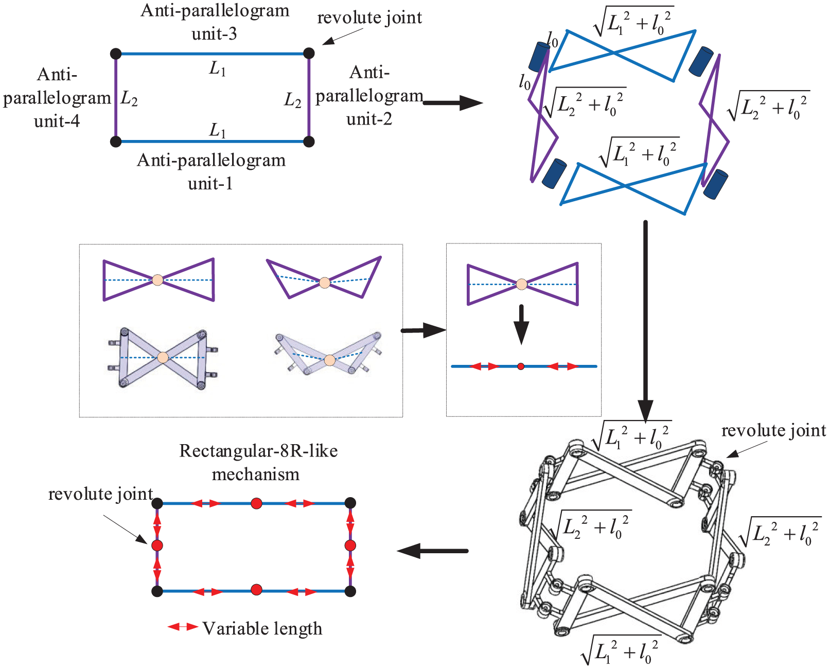
Construction method of Rectangular-8R-like mechanism.
Combined with Figure 1, the specific design method can be obtained as follows: Firstly, determine the length of the long side (L1) and the short side (L2) of the rectangle, as well as the length (l0) of the short side (the connecting link) of the anti-parallelogram unit. Then, calculate the lengths of the two sets of diagonal links (l1 and l2) of the anti-parallelogram using the Pythagorean theorem, resulting in two sets of anti-parallelograms. Finally, connect the midpoints of the short sides through four revolute joints to form a rectangular-like mechanism with a long side of L1, a short side of L2, and the length of the short side (the connecting link) of the anti-parallelograms being l0.
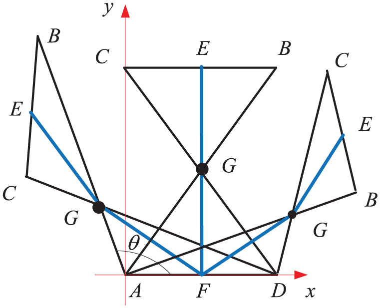
Obviously, the axes of the revolute joints in the Rectangular-8R-like mechanism are not perfectly parallel, and the simplified virtual revolute joints of the anti-parallelogram unit are always perpendicular to the plane of the unit and perpendicular to the axes of the original revolute joints of the rectangle. On the other hand, during motion, the axes of the original revolute joints of the rectangle exhibit intersections, parallelism, and coincidence. As shown in Figure 2, during the whole motion, both the position and direction of the revolute joints will change, except at specific positions. Consequently, the mechanism is only an approximate rectangle, not a strict one. The link length of the simplified 8R mechanism is related to the link length of the anti-parallelogram unit. As shown in Figure 3, when the diagonal link AB = CD = l1, and the connecting link AD = BC = l0, the angle between BC and AD is θ, the virtual link length can be expressed as follows:

Change of Rectangular-8R-like mechanism.
The relationship between the virtual link length and the angle during motion.
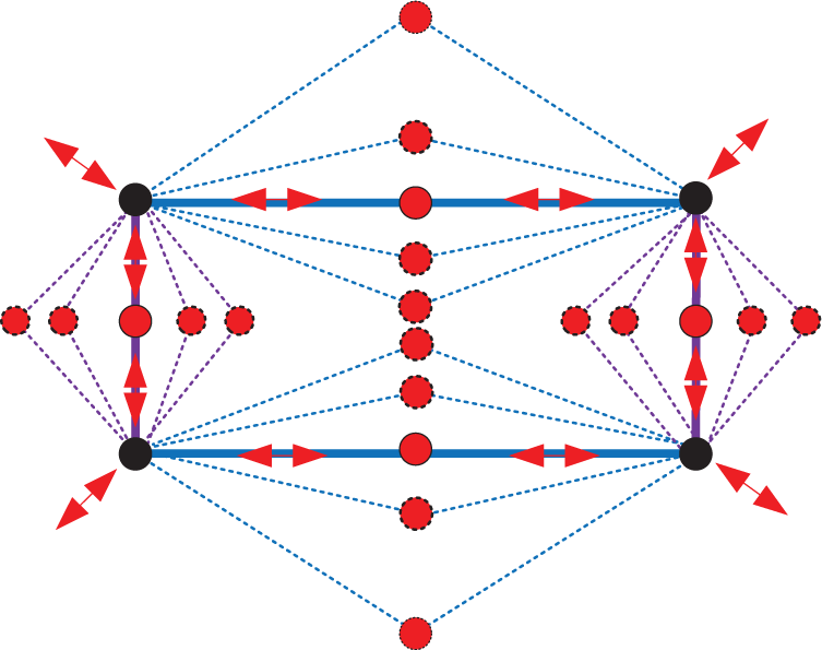
Therefore, the constructed Rectangular-8R-like mechanism can be simplified as an 8R-like mechanism with real-time changes of virtual link length during motion. Moreover, the mechanism has two symmetric surfaces, enabling it to perform tumbling movement by using the symmetric characteristics to adapt to different terrain and working conditions.
DOF analysis of multi-mode mechanism
According to the characteristics of the traditional 8R mechanism and the Rectangular-8R-like mechanism constructed in this paper, the mechanism mainly consists of three distinct motion modes: the symmetrical tumbling mode, the quasi-spherical rolling mode, and the bifurcation mode of both. The DOF of the three modes are analyzed below.
DOF of symmetrical tumbling mode
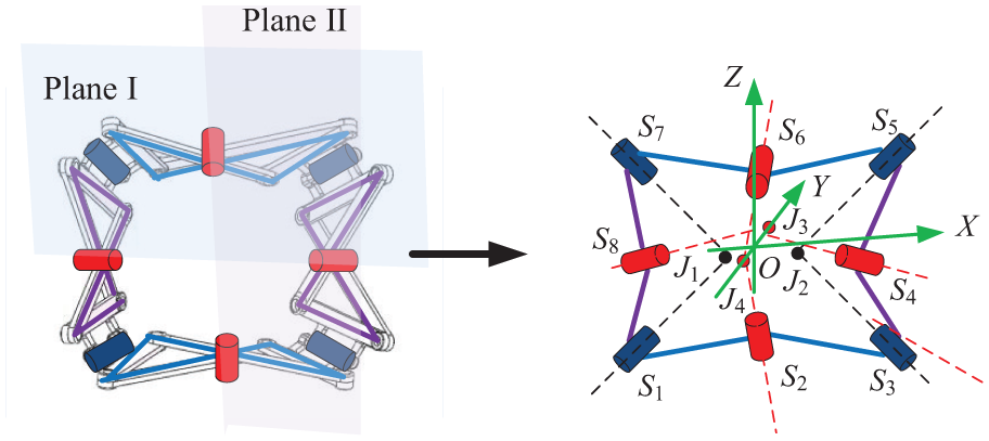
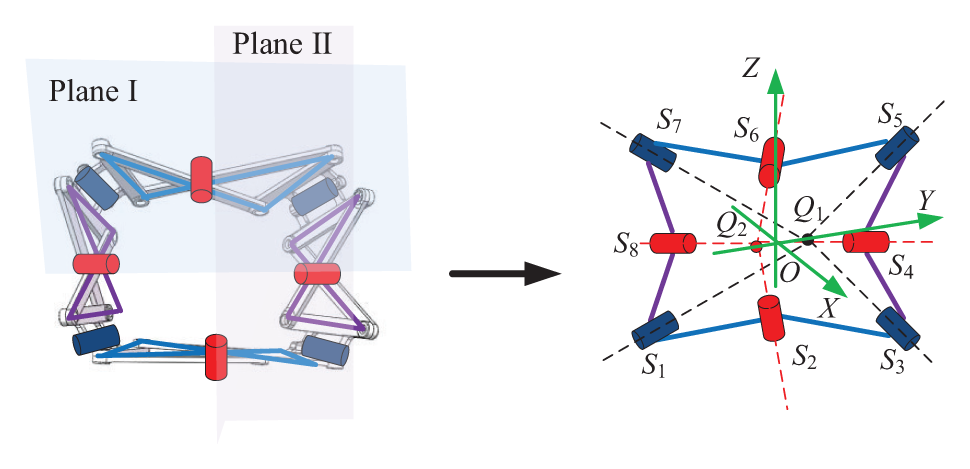
As shown in Figure 4, the eight revolute joints are denoted as S i (i = 1, …, 8). During the motion process, the intersection of axes S1 and S7 is denoted as J1, the intersection of axes S3 and S5 is denoted as J2, the intersection of axes S4 and S8 is denoted as J3, the intersection of axes S2 and S6 is denoted as J4. When J1 and J2 do not coincide, J3 and J4 also do not coincide, the planes I and II of this Rectangular-8R-like mechanism are symmetrical planes, respectively. This configuration can be simplified to an 8R mechanism with two symmetrical planes. A Cartesian coordinate system O-XYZ is established as follows: the origin O is located at the midpoint of the line between intersection points J3 and J4, the X-axis is parallel to the line between intersection points J1 and J2 through the origin O, the Y-axis is aligned along the line connecting J3 and J4, and the Z-axis is determined by the right-hand rule. According to the characteristics of Rectangular-8R-like mechanism and anti-parallelogram unit, it is evident that any two adjacent revolute joints among the eight are perpendicular to each other.
Coordinate establishment of symmetrical tumbling mode.
Let the length of the line segment connecting the intersections points J1 and J2 be 2f, and the length of the line segment connecting the intersections points J3 and J4 be 2g. Let h denote the distance between the line on which the X-axis lies and the line segment connecting J1 and J2. Let 2ν1 indicate the angle between the axes of the revolute joints S4 and S8, and let 2ν2 indicate the angle between the axes of the revolute joints S2 and S6. According to the Screw theory, 31 the screw coordinates of the eight revolute joints can be obtained as follows:

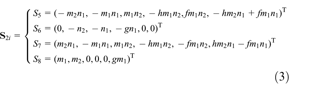
where m1 denotes sinν1, m2 denotes cosν1, n1 denotes sinν2, n2 denotes cosν2.
The constraint screw of eight revolute joints can be obtained from equations (2) and (3).


Therefore, according to equations (4) and (5), it is obtained that dim(
DOF of quasi-spherical rolling mode
As shown in Figure 5, during the motion process, the axes of revolute joints S1, S3, S5, and S7 intersect at point P3, the axes of S4 and S6 intersect at point P2, and the axes of S2 and S8 intersect at point P1. When the mechanism has no symmetry plane and is symmetrical about its center, the Rectangular-8R-like mechanism transitions into a quasi-spherical mode. In this mode, it can be simplified as a quasi-spherical 8R mechanism. A Cartesian coordinate system O-XYZ is established, in which the origin O is located at the intersection point P3, the X-axis passes through the origin O and is perpendicular to the line connecting points P1 and P2, the Y-axis is parallel to the line connecting points P1 and P2, and the Z-axis is determined by the right-hand rule. According to the characteristics of the quasi-spherical Rectangular-8R-like mechanism and the anti-parallelogram unit, the two adjacent revolute joints among the eight are perpendicular to each other.

Coordinate establishment of quasi-spherical mode.
Let the length of the line segment connecting the intersection points P1 and P2 be 2p, and the distance between the Y-axis and the line segment connecting the intersection points P1 and P2 be q. Let 2δ1 indicate the angle between the axes of the revolute joints S1 and S5, and 2δ2 indicate the angle between the axes of the revolute joints S3 and S7. According to the Screw theory, the screw coordinates of the eight revolute joints can be obtained as follows:

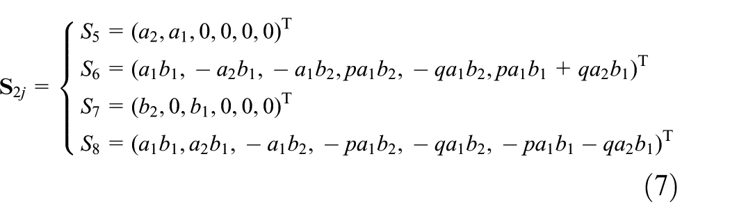
Where a1 denotes sinδ1, a2 denotes cosδ1, b1 denotes sinδ2, b2 denotes cosδ2.
The constraint screw of eight revolute joints can be obtained from equations (6) and (7).


Therefore, according to equations (8) and (9), it is obtained that dim(
DOF of bifurcation mode
As shown in Figure 6, during the motion process, the axes of revolute joints S1, S3, S5, and S7 intersect at point Q1, and the axes of S2, S4, S6, and S8 intersect at point Q2. When the mechanism has two symmetrical planes and is symmetrical about its center, the Rectangular-8R-like mechanism transitions into the bifurcation position between the symmetric tumbling mode and the quasi-spherical mode. In this mode, it can be simplified as a symmetric-quasi-spherical 8R-like mechanism. A Cartesian coordinate system O-XYZ is established, where the origin O is located at the midpoint of the line segment between the intersection points Q1 and Q2, the X-axis is the line that perpendicularly bisects the line segment connecting Q1 and Q2 and is located on the plane of the revolute joints S4 and S8, the Y-axis is the line that passes through the origin O and connects the intersection points Q1 and Q2, and the Z-axis is determined by the right-hand rule. According to the characteristics of the quasi-spherical Rectangular-8R-like mechanism and the anti-parallelogram unit, the two adjacent revolute joints among the eight are perpendicular to each other.
Coordinate establishment of bifurcation mode.
Let the length of the line segment connecting the intersection points Q1 and Q2 be 2c, let 2η1 represent the angle between the axes of the revolute joints S1 and S5, let 2η2 represent the angle between the axes of the revolute joints S3 and S7. The screw coordinates of the eight revolute joints can be obtained according to the Screw theory. Combining the characteristics of Rectangular-8R-like mechanism and anti-parallelogram unit, along with the symmetric tumbling mode and the quasi-spherical mode, the screw coordinates of eight revolute joints can be obtained as follows:


Where d1 denotes sinη1, d2 denotes cosη1, e1 denotes sinη2, e2 denotes cosη2.
The constraint screw of eight revolute joints can be obtained from equations (10) and (11).
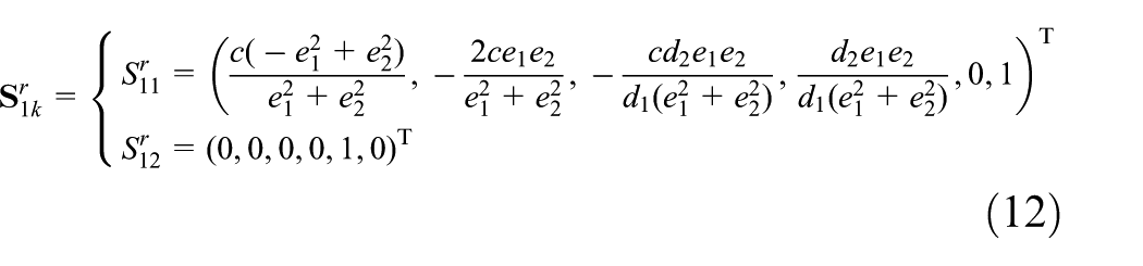

Therefore, according to equations (12) and (13), it is obtained that dim(
Motion modes analysis of multi-mode mechanism
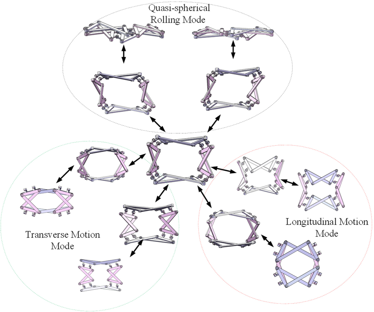
According to the DOF analysis of the multi-mode mechanism presented in section “DOF analysis of multi-mode mechanism,” the three main motion modes of the constructed Rectangular-8R-like mechanism (symmetrical tumbling mode, quasi-spherical rolling mode, and bifurcation mode) and their characteristics can be obtained.
Motion mode of symmetrical tumbling mode
According to the symmetry characteristics of Rectangular-8R-like mechanism and the motion characteristics of the anti-parallelogram unit mechanism, as shown in Figure 7, the multi-mode mechanism has four anti-parallelogram units. In this mechanism, unit-1 and unit-3 are the identical (group 1), unit 2 and unit 4 are the identical (group 2). Due to its symmetry and the motion characteristics of the anti-parallelogram unit, the two groups of units behave identically in real time. In the symmetrical tumbling mode, the mechanism can exhibit two distinct motion modes: transverse motion and longitudinal motion. The transverse motion is achieved through the movement of group 1, while the longitudinal motion is achieved through the movement of group 2. As shown in Figure 8, a schematic diagram of lateral motion shows that when the unit of group 2 remains unchanged, the transverse movement can be realized with the left and right movement of group 1. Similarly, as shown in Figure 9, when the unit of group 1 remains unchanged, the longitudinal movement can be realized with the up and down movement of group 2. Furthermore, even the combination of transverse and longitudinal motion can generate more complex surging motion.

The three-dimensional model of Rectangular-8R-like mechanism.

Transverse motion 3D model of symmetrical tumbling mode.

Longitudinal motion 3D model of symmetrical tumbling mode.
Motion mode of quasi-spherical rolling mode
According to the analysis of the DOF of the quasi-spherical rolling mode, the characteristics of the quasi-spherical Rectangular-8R-like mechanism, and the motion characteristics of the anti-parallelogram unit, the mechanism becomes a quasi-spherical four-bar mechanism in this quasi-spherical rolling mode. At each position, the anti-parallelogram can be regarded as a simple link, however, due to the characteristics of the anti-parallelogram unit mechanism, the link length changes in real time. That is, each link length corresponds to a specific spherical four-bar mechanism. As shown in Figures 10 and 11, two distinct motion modes can be observed under different link lengths in the quasi-spherical rolling mode.

3D model for the position-I of quasi-spherical rolling mode.

3D model for the position-II of quasi-spherical rolling mode.
Motion mode of bifurcation mode
The bifurcation mode of the Rectangular-8R-like mechanism is the intermediate mode between the symmetrical tumbling mode and the quasi-spherical mode. Therefore, in this symmetric-quasi-spherical 8R-like configuration, the mechanism can perform the longitudinal motion mode, the transverse motion mode, and the quasi-spherical rolling mode at this position, as shown in Figure 12. In this bifurcation mode, the longitudinal motion mode, the transverse motion mode, and the quasi-spherical rolling mode can be selected and switched by adjusting the angle of a single anti-parallelogram unit and the inter-unit angles.
3D model of bifurcation mode.
Prototype model verification
According to the analysis of the first two sections, a principle prototype model is fabricated, the 3D-printed model is shown in Figure 13. Based on a rectangular with width L2 = 66 mm and length L1 = 88 mm, and two sets of anti-parallelogram units with connecting link l0 = 66 mm, the Rectangular-8R-like mechanism is designed. Using the Pythagorean theorem, the lengths of the diagonal links are calculated as l1 = 110 mm for unit-3 and l2 = 93.34 mm for unit-4. It can be observed that the constructed Rectangular-8R-like mechanism is rectangular in the illustrated state. The following section verifies the motion modes of the mechanism, including symmetrical tumbling mode, quasi-spherical rolling mode, and bifurcation mode.
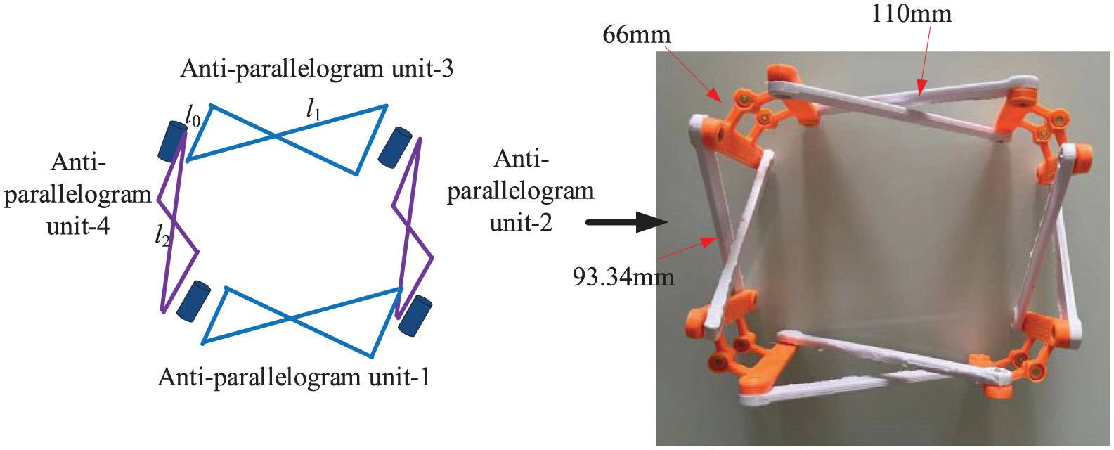
3D-printed model.
As shown in Figures 14 and 15, the transverse and longitudinal motion modes of the Rectangular-8R-like mechanism in the symmetrical tumbling mode are presented. It can be observed that, when the units of group 2 (units 2 and 4 in Figure 13) remain unchanged, the transverse movement can be realized with the left and right movements of group 1 (units 1 and 3 in Figure 13) (Figure 14). Similarly, when the unit of group 1 is unchanged, the longitudinal motion can be realized with the up and down movement of group 2 (Figure 15).

Verification of transverse motion mode of symmetrical tumbling mode.

Verification of longitudinal motion mode of symmetrical tumbling mode.
As shown in Figure 16, the motion mode of Rectangular-8R-like mechanism in the quasi-spherical rolling mode shows that the mechanism becomes a quasi-spherical four-bar mechanism. In this mode, the anti-parallelogram can be regarded as a simple link, but because of the characteristics of the anti-parallelogram unit mechanism, the link length changes in real time, that is, each specific length corresponds to a distinct spherical four-bar mechanism.

Verification of motion mode of the quasi-spherical rolling mode.
Obviously, in the bifurcation mode, the Rectangular-8R-like mechanism can exhibit the motion characteristics of both the symmetrical tumbling mode and the quasi-spherical mode, as shown in Figure 17. Moreover, the bifurcation mode can be converted into the longitudinal motion mode, the transverse motion mode, and the quasi-spherical rolling mode. By adjusting the angle of a single anti-parallelogram unit and the angles between units, selecting and witching among three modes can be achieved. It can be indicated that the mechanism can be used as a multi-mode mobile mechanism for further research in the future. In addition, due to its characteristics such as overturning and folding, it can also be used as a structural subunit of large deployable mechanisms.

Verification of motion mode of bifurcation mode.
Conclusions
In this paper, a multi-mode Rectangular-8R-like mechanism is designed. The mechanism is composed of two different groups of anti-parallelogram units and possesses multiple motion modes, including the symmetrical tumbling mode, the quasi-spherical rolling mode, and the bifurcation mode. Among these, the symmetrical tumbling mode has two sub-modes: the longitudinal motion mode and the transverse motion mode. The bifurcation mode is an intermediate state between the symmetrical tumbling mode and the quasi-spherical rolling mode. The DOF, motion modes, and motion characteristics of the three modes are obtained. A 3D model is designed to verify its motion modes based on the analysis results. Finally, a prototype model is fabricated to verify the correctness of the analysis results and the feasibility of movement. It is concluded that this kind of multi-mode Rectangular-8R-like mechanism can subsequently utilize the quasi-spherical rolling mode for rapid rolling, the symmetrical tumbling mode to surmount the obstacle, and the bifurcation mode to switch. Therefore, the multi-mode mechanism designed in this paper has certain application prospects in mobile mechanisms and deployable mechanisms.
The multi-mode mechanism designed in this paper has been verified its multiple motion modes through prototypes and experiments. However, only the design method and feasibility study have been completed at the mechanism science level. If it is to be applied in the mobile mechanisms or the deployable mechanisms, further exploration is still needed. In the future, it could be further developed into a mobile robot, and the layout and design of the driving system should be studied first. In addition, the control strategy for mode switching, especially the collaborative control method, is also a key issue that urgently needs to be addressed. In terms of network design for deployable mechanisms, this multi-mode mechanism can be used as the basic sub-unit to construct a large deployable mechanism. However, its network methods and corresponding analysis approaches still need in-depth research.
Footnotes
Handling Editor: Chenhui Liang
Author contributions
Study conception and design: Z. Yu, X. Sun; draft manuscript preparation: Z. Yu, X. Sun, and Q. Zheng; supervision: F. Zhou. All authors reviewed the results and approved the final version of the manuscript.
Funding
The authors disclosed receipt of the following financial support for the research, authorship, and/or publication of this article: This work has been supported by the Intelligent Manufacturing and data Application Shandong Engineering Research Center.
Declaration of conflicting interests
The authors declared no potential conflicts of interest with respect to the research, authorship, and/or publication of this article.
Data availability statement
No new data were created in this study.