
Abstract
Quadruped bionic robot has a strong adaptability to the environment, compared with wheeled and tracked robots, it has superior motion performance, and has a wide range of application prospects in rescue and disaster relief, ground mine clearance, mountain transportation, so it has become a research hotspot all over the world. Leg structure is an important embodiment of the superior performance of quadruped robot, and it is also the key and difficult point of design. This article proposes a novel quadruped robot with waist structure, which can complete a variety of gait forms. Based on the theory of linkage mechanism, a novel leg structure is designed with anti-parallelogram mechanism, which improves the strength and stiffness of the robot. Using D-H description method, the kinematics analysis of this quadruped robot single leg is carried out. On this basis, in order to ensure the foot contact with the ground and achieve zero impact, polynomial programming is used to plan the foot trajectory of swing phase and support phase. Based on the static stability margin, the optimal static gait of the quadruped robot is planned. A co-simulation study has been carried out to investigate further the validity and effectiveness of the quadruped robot on gait. The simulation results clearly show the robot can walk steadily and its input and output meet the expected requirements. The solid prototype platform is built, and the trajectory planning experiment of single leg is carried out, and the foot trajectory of single leg is obtained by using laser tracker. The gait planning algorithm is applied to the whole robot, and the results show that the robot can walk according to the scheduled gait, which proves the effectiveness of the proposed algorithm.
Introduction
After 100 of millions of years of evolution and development, animals have the most perfect biological characteristics and the best skeletal structure. 1 Learning from nature and designing bionic robots are one of the fast developing fields in recent years. 2 Mobile robots have been applied in many fields of life and made great progress. 3 Onwubolu et al. 4 presented the design, implementation, and experimental results of the motion controller design of an effective data communication mobile robot platform developed for independently controlling each robotic drive wheel. Carnegie and Cordes 5 described the design and construction of a low-cost caterpillar-track robot intended for outdoor use in a variety of irregular terrains. Quadruped bionic robots can walk in complex unstructured environments and perform many dangerous tasks instead of human beings, which play an active role in nuclear energy industry, military demining, disaster relief and mining and have become the focus of research by major scientific research institutions. 6
In 2015, Japan’s Chiba Institute of technology developed a new type of eight legged robot halluca II, which is similar to the tortoise in appearance. It integrates many sensors and control systems, and has autonomous navigation function, which can achieve obstacle avoidance effect. 7 Beili Nezha quadruped robot was designed by Beijing University of Technology. It uses parallel legs as the leg structure, which has very strong load capacity, but the control is relatively complex. 8 Luo et al. 9 deduced three kinds of foot trajectory, and completed the motion stability of the robot under the specific gait. In order to improve the walking stability and obstacle surmounting ability of the robot on the slope, Zhang et al. 10 designed a goat like quadruped robot based on the bionic prototype of goat. A low contact compact foot trajectory planning method based on high-order polynomial curve was adopted to realise the foot trajectory planning of the robot in the swing stage and standing stage. Zhao et al. 11 developed an electric wheel-legged robot, which combined impedance control methods with the robot. In order to simplify the analysis of tandem legs, many scholars introduced the spring-loaded inverted pendulum model to analyse quadruped robots by referring to the results of biology, which provided a reference for the control of single leg and the whole machine. 12 Despite its simple configuration and ease of control, the SLIP model is very effective to describe dynamic behaviours of animals of many kinds. 13 Han et al., 14 studied how to adjust the gait of legs in three-dimensional space to achieve the spatial stability of the robot.
Leg configuration is an important index to evaluate the performance of a quadruped robot and it is also a technical difficulty to overcome at this stage. The leg structure with strong load-bearing ability, easy to control and simple design is a topic that scientists are tirelessly exploring, so far the main leg configurations are series leg, parallel leg and hybrid leg. In the research of series legs, Zhang et al. 15 designed a mechanical leg with five degrees of freedom, analysed its kinematics and completed the trajectory planning of one leg. Based on the structural characteristics of animal hind legs, Ma 16 proposed a new energy-saving leg configuration and realised the diagonal trot gait of the robot. In the aspect of parallel legs research, Waseda University of Japan designed walking chair with parallel mechanism, and Hirosaki Research Laboratory successfully designed Para-Walker robot. 17 Wang et al. 18 introduced parallel mechanism into quadruped robot, which improved the strength and stiffness of one leg of the robot. In 2016, Yanshan University successfully realised the motion of quadruped robot by using 3-UPS parallel mechanism as the leg structure of quadruped robot. 19 In the research of hybrid legs, Zhou and Gao 20 regard hybrid mechanism as a single leg of humanoid robot, which enhances the strength of the robot leg and enlarges the workspace of the robot. Wang 21 of Zhengzhou University proposed a new series-parallel legged robot and studied its dynamics. Wang et al. 22 proposed a new parallel series quadruped robot, and comprehensively analysed the leg configuration and performance of the robot. Qin et al. 23 improved the leg structure of the quadruped robot and designed by using the mechanism of the lateral swing posture of the leg of the hoof animal. From the above research, it is found that the series leg has larger workspace, but lower strength and stiffness; the parallel leg has larger strength and stiffness, but the control is relatively complex. In view of the shortcomings of series leg and parallel leg, a new leg configuration is needed.
The innovation of this article is: (i) leg mechanism with anti-parallelogram is proposed as the single leg configuration for the quadruped robot, which not only improves the strength and stiffness of the robot leg, but also makes the control simple and easy to implement; the whole leg is made up of parallelogram mechanism and anti-parallelogram mechanism, which only needs two drives to realise the movement. The motors are all arranged on the fuselage, and the efficiency of the joint motor is greatly improved by the transmission of power through the connecting rod, which overcomes the problem of the motor directly driving the lower leg joint and the increase of the leg mass. (ii) In gait planning, in order to reduce the impact of the ground to the foot when the robot moves, polynomial is used to plan the zero impact trajectory of the foot. (iii) In some special cases, the stability of the robot will decrease, therefore, the time of the supporting phase can be increased to increase the duty cycle of the quadruped robot, so as to improve the stability of the robot.
Structural description of the robot
The proposed quadruped bionic robot consists of a front body I, a waist mechanism II, a back body III, a leg mechanism IV and a side pendulum mechanism V, as shown in Figure 1. The waist mechanism is essentially a three-degree-of-freedom parallel mechanism. The first and second branches are UPS structure and the other one is UP structure. Here P refers to the mobile pair, U is Hooke hinge and S is ball pair. This article mainly focuses on the research of robot gait, which does not involve the waist movement. Therefore, in the later analysis, the waist structure is toughened to make it firmly connected with the front body and the back body. The whole machine is symmetrical configuration of front elbow and back knee. All motors are integrated in the fuselage, which greatly reduces the leg inertia.
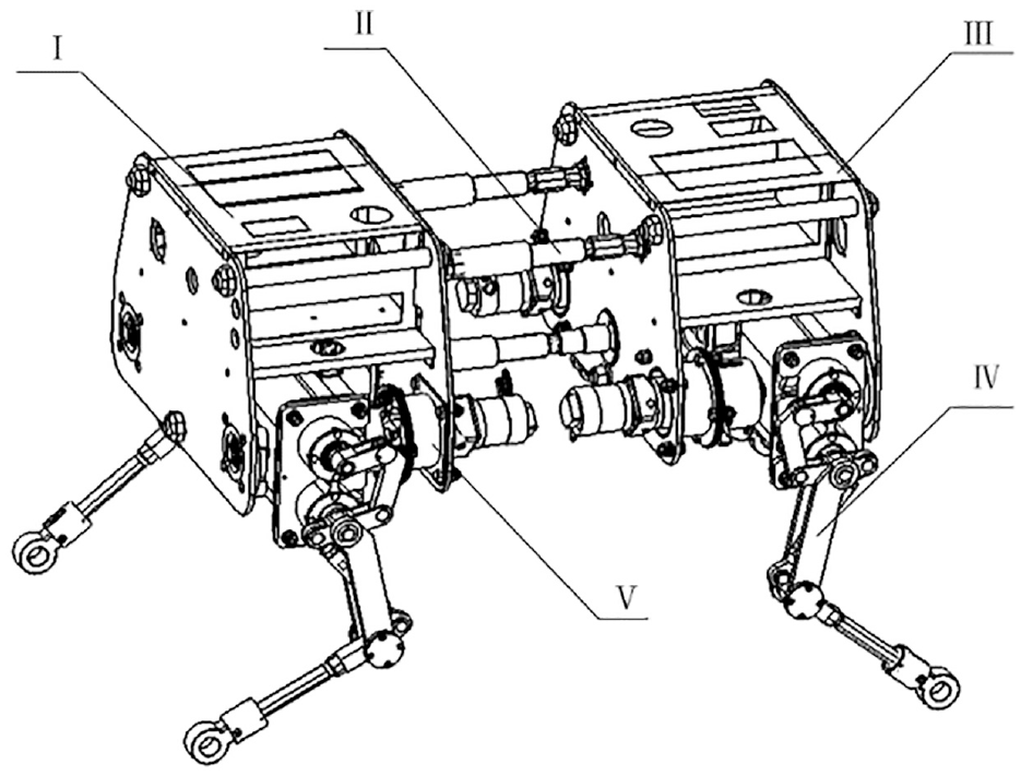
Three-dimensional model of MQ robot.
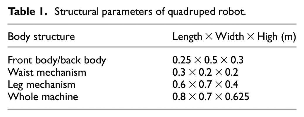
The front body is connected with the back body through the waist structure, which enables the front body to have pitching, left-right rotation and front-back telescopic movement relative to the back body. Leg mechanism is mainly composed of parallelogram mechanism and anti-parallelogram mechanism, which makes the leg have greater strength and stiffness, and relatively simple control, which is more in line with the law of mammalian motion. Table 1 gives the design parameters of the quadruped robot.
Structural parameters of quadruped robot.
Single leg forward kinematics analysis
The leg configuration of quadruped robot determines the motion performance of the whole machine, and its structure directly affects the walking stability, so the leg design of robot is particularly important. From the enlarged single leg model in Figure 2, it can be seen that the whole leg is composed of parallelogram mechanism and anti-parallelogram mechanism. The movement of the lower leg is transferred from the parallelogram mechanism to the anti-parallelogram mechanism, so as to realise the movement of the foot end. The crus input shaft is mainly used to lift the leg height of the robot without the displacement of the fuselage movement, which provides a guarantee for the robot to cross over obstacles. The motion of the thigh is relatively simple. The thigh input shaft drives the thigh to realise the motion of the fuselage relative to the ground.
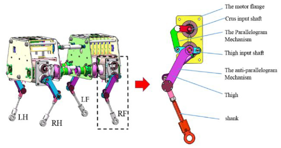
Enlarged single leg model.
The design of the robot mainly adopts the front elbow and rear knee joint configuration which is recognised by the industry at present, which can increase the walking stability of the robot and reduce the energy consumption in the process of motion. From Figure 2, it can be seen that this kind of leg structure has greater strength and rigidity than the series leg, and has greater working space and flexibility than the parallel leg. Only two main drives are needed to realise the leg movement of the robot, which shows the operability of its control.
Figure 3 is the kinematics model of the robot’s single leg, which shows the solution process of the whole machine kinematics. Figure 3(c) shows the structural form of the anti-parallelogram leg and the relevant parameters of the leg. The coordinate system O-xy is established at the midpoint of AF. The direction of X is perpendicular to AF, the direction of Y axis coincides with AF, the angle between FG and Y axis is, the angle between AD and Y axis is, and the angle between AD and DE is θ3, AO = L1, AD = L2, ED = L3. The forward kinematics of the robot’s single leg is known as the input angle of the side pendulum motor, the input angle of the hip joint motor, the input angle of the knee joint motor and the parameters of the rod, so that the position of the foot end relative to the hip joint coordinate system O-x0y0z0 can be obtained. In order to facilitate mechanism analysis, the leg mechanism is simplified to a series leg configuration as shown in Figure 3(a). The body coordinate system O-XYZ is established in the centre of the body, the joint coordinate system is established at the joint of the robot, and the foot end coordinate system O-x3y3z3 is established.
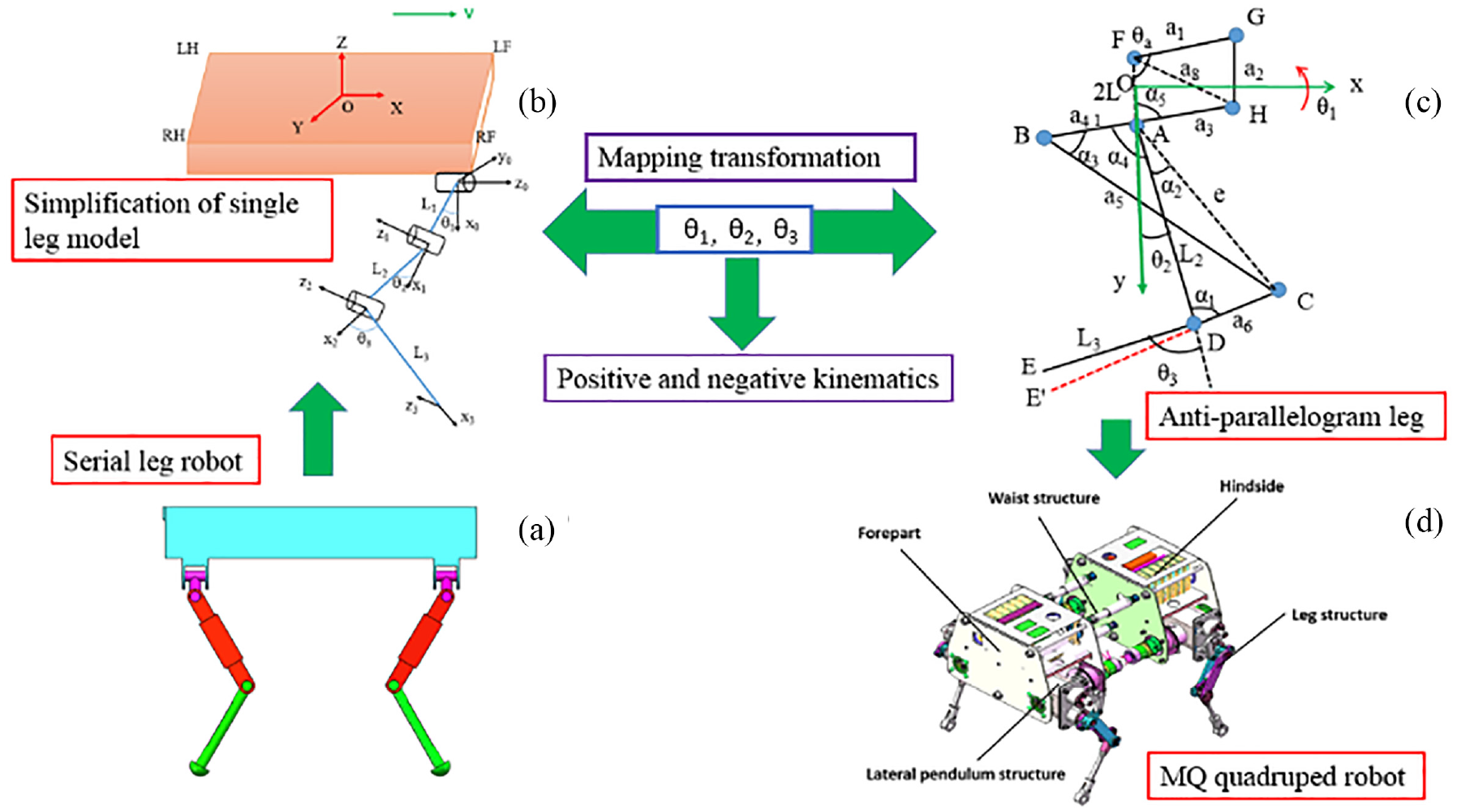
The kinematics model of the robot's single leg: (a) Serial leg robot, (b) Simplification of single leg model, (c) Anti-parallelogram leg, and (d) MQ quadruped robot.
The member parameters and forward and inverse kinematics will be obtained by D-H method and geometric relationship. The kinematics of anti-parallelogram leg mechanism is relatively complex, which can be obtained from the series leg configuration. First, take out the single leg of the serial robot (Figure 3(a)) to establish the D-H coordinate system, as shown in Figure 3(b). The joint angle mapping relationship between the series leg and the anti-parallelogram leg is established through the geometric relationship. The joint angle of the anti-parallelogram leg can be transformed into the conventional series leg joint angle for analysis. That is to establish the mapping relationship between Figure 3(b) and (c). Finally, according to the joint angle information, the motor can realise the motion control of the robot.
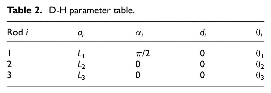
From Figure 3(b), we can get the parameter transfer relationship between coordinate systems and write out the D-H parameter table, as shown in Table 2.
D-H parameter table.
According to the homogeneous transformation matrix of formula (1), the homogeneous transformation matrix of the foot end relative to the hip joint can be obtained as follows:
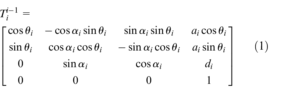
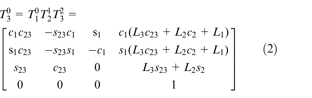
where:
Equation (2) shows that the position coordinates of the foot end relative to the hip joint are:


Single leg inverse kinematics analysis
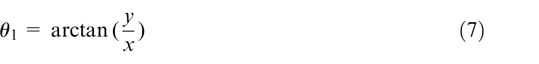
Inverse kinematics of robots refers to the inverse solution of joint variables θ1, θ2, θ3 and θa .when the position of the foot end and the parameters of the rod are known. Inverse kinematics is the basis of analysing the workspace, trajectory planning and motion control of robot, and it is an indispensable part of robot kinematics.
According to equations (3) and (4):
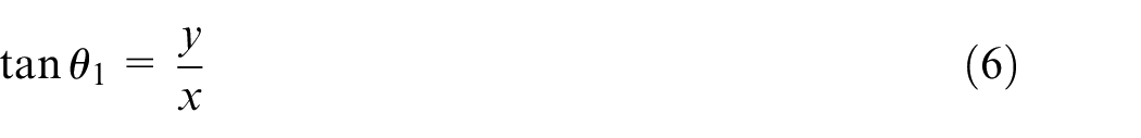
So that we can have:
From equations (3) and (4):
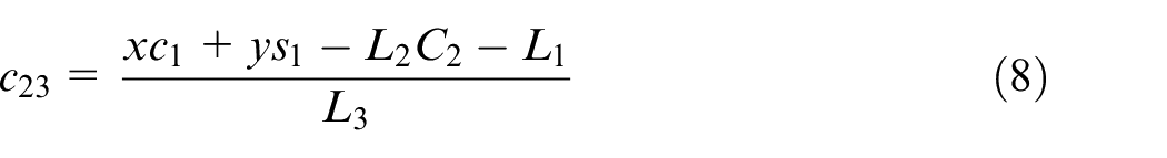
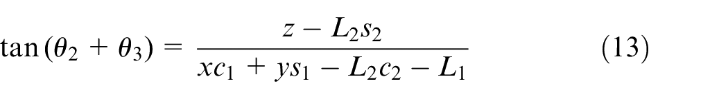
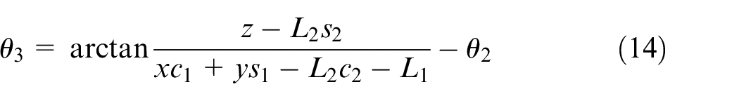
The transformation of equation (5) is as follows:
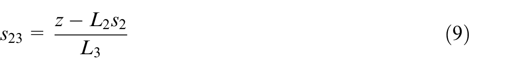
According to equations (8) and (9):
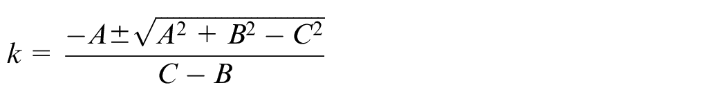
Resolving the above formula, we can obtain:

where:


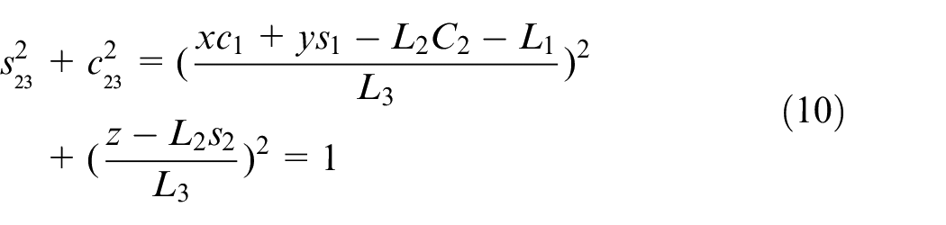
Based on equations (8) and (9), we can obtain:
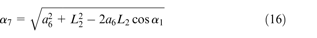
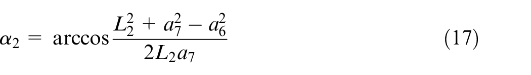
Because the angle between CE and CE’ is 10°, so:

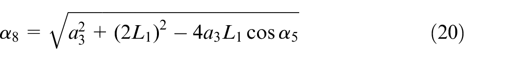
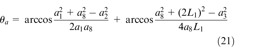
According to the cosine theorem, we can obtain:

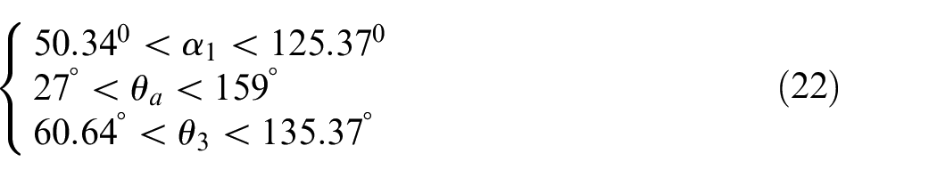
From the perspective of mechanism constraints, it can be concluded that the angular constraint of the mechanism is as follows:
The analysis shows that the size of ∠CDE has a great impact on the foot workspace. In order to explore the impact of ∠CDE on the workspace and obtain the optimal structural parameters. Given mechanism parameters: a1 = 50 mm, a3 = 50 mm, a2 = 84 mm, l1 = 42 mm, l2 = 170 mm, a5 = 170 mm, l5 = 170, a4 = 34 mm, a6 = 34 mm.
Monte Carlo method is used to obtain single leg workspace with ∠CDE of 170°, 140° and 110°. Figure 4 shows that the shape of the workspace at the foot of one leg is similar to that of a heart, and the blank area in the middle is the singularity of the mechanism. The workspace of one leg is changed from big to small, and the blank area in the middle is changed from small to large, which proves that when ∠CDE = 170°,the performance of the robot is the best, so that the angle of ∠CDE is set at 170°.
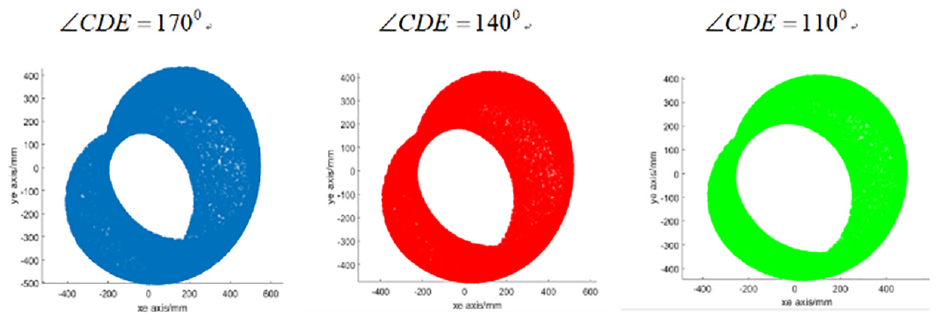
The effect of ∠CDE on foot workspace.
Gait planning of quadruped robot
Static stability analysis of the quadruped robot
In static walking, each leg of the quadruped robot moves in turn to achieve the movement of the body. The phase difference of each leg is 0.25, and the duty cycle is β = 0.75. There are kinds of walking sequence in the course of walking, which are 1-2-3-4, 1-2-4-3, 1-3-2-4, 1-3-4-2, 1-4-2-3 and 1-4-3-2. However, the influence of these six walking sequence on the stability of the robot is different. Static walking means that the horizontal projection of the centre of mass of the robot is located in the supporting polygon, and the quadruped robot is statically stable.
Static stability margin SSM is the shortest distance from the projection point of the centre of mass to each side of the supporting polygon. The stability of the robot can be measured by the static stability margin. Figure 5 shows the static stability margin of the robot when the right front leg (RF) is in the swing phase. If the stability margin is greater than zero, it indicates that the robot is statically stable. In order to maintain the static stability of the robot, it is necessary to select the most stable gait among the six walking gaits as the walking gait of the robot.
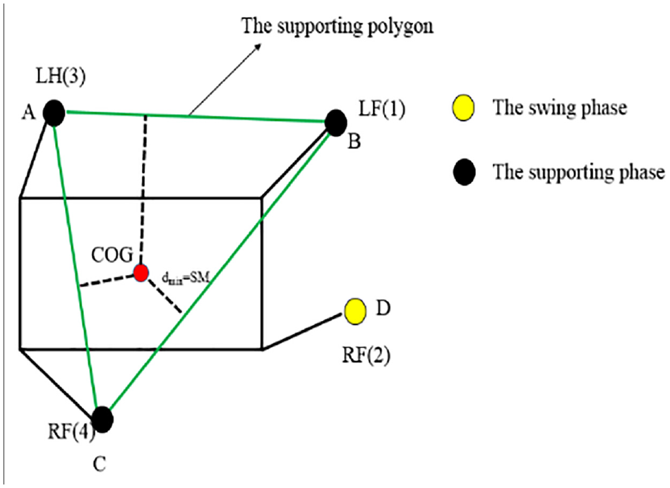
Quadruped robot stability margin.
According to previous studies, the relationship between the static stability margin and duty cycle of the robot is obtained as shown in Table 3, which shows that when quadruped robot uses the gait of 1-4-2-3, the stability margin is the largest and it can ensure that the stability margin is always greater than zero. 24 In nature, most mammals choose this motion mode to improve their static stability. Therefore, the gait form of 1-4-2-3 is chosen as the motion phase sequence of the quadruped robot in this paper.
Effect of gait on robot stability margin.
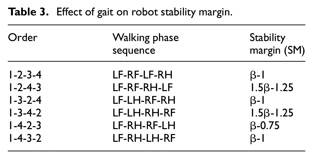
Figure 6 shows the gait planning flow chart of the robot. From the graph, it can be seen that the robot has four feet touching the ground, which can make the robot have higher stability. The four legs of the quadruped robot step in turn, so as to push the body forward, so as to achieve the goal of robot walking
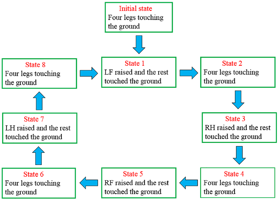
Gait planning flow chart.
Single leg trajectory planning
Trajectory planning is an important part for quadruped robot to walk stably, in order to reduce the impact between the foot and the ground and realise the stability of the robot, it is necessary to plan the foot trajectory of the robot according to the specific terrain. Since polynomial is more in line with the motion characteristics of organisms, cubic polynomial is used for trajectory planning. The o-xy coordinate system is established at the hip joint of the robot, where the x-axis points to the forward direction and the y-axis points vertically upward. The step length of single leg from lifting to falling is S, the distance from the ground to hip joint is H and the distance from the highest point of step to hip joint is h. P-P1-P2-P represents the trajectory of a single leg in a period. Figure 7 shows the schematic diagram of foot end trajectory, and the leg lifting height is H-h.
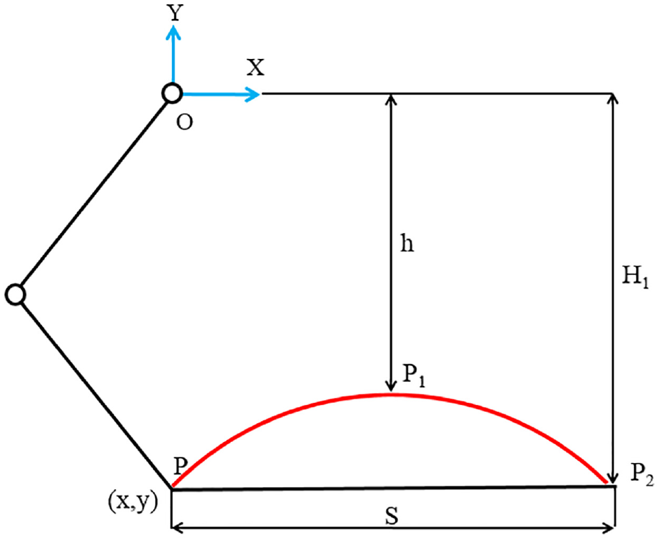
Schematic diagram of foot trajectory.
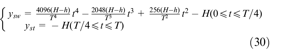
The displacement equation of swing phase is planned in [0, T/4], and that of support phase is planned in [T/4, T].
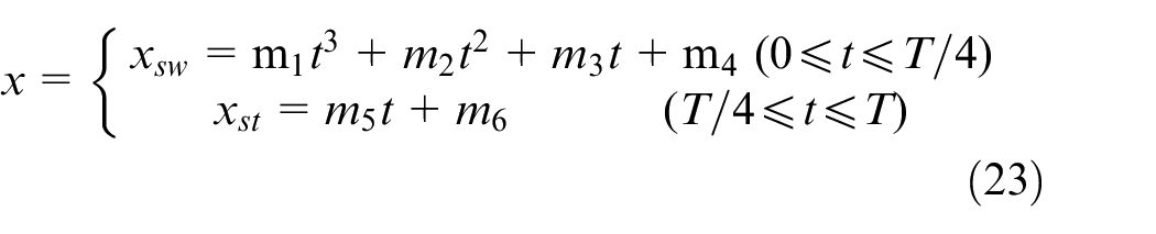
where, m1, m2, m3, m4, m5 and m6 represent cubic polynomial coefficients, which need to be solved.
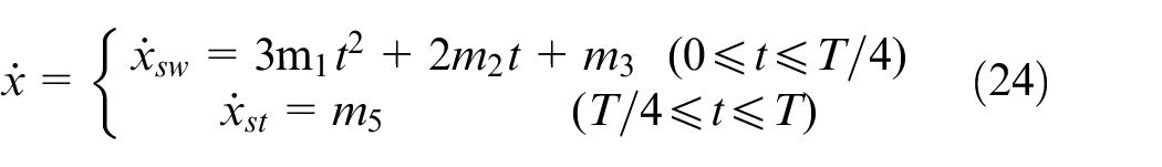
The velocity expression equation (24) can be obtained by deriving equation (23):
The given boundary condition is:
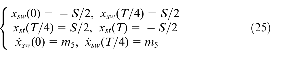
By introducing the boundary condition equation (25) into equations (24) and (23), the horizontal displacement equation of swing phase is obtained as follows:
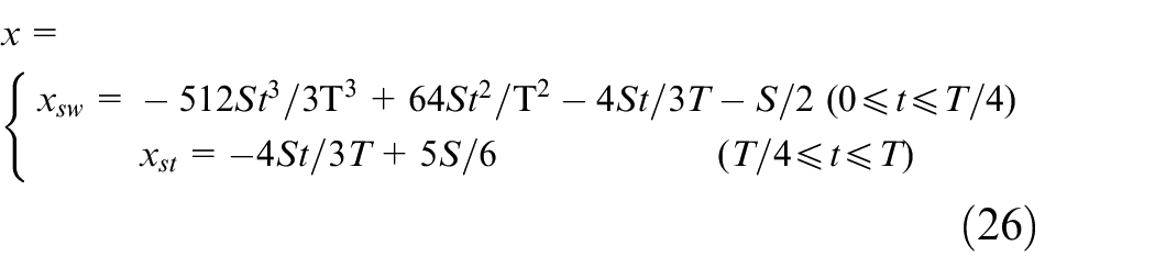
The displacement equation in Y direction is given as follows:
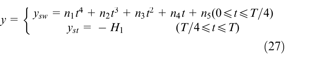
where, n1, n2, n3, n4 and n5 represent cubic polynomial coefficients, which need to be solved.
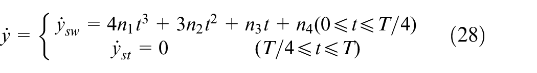
The velocity equation derived from equation (27) is as follows:
The initial conditions for the given Y direction are as follows:
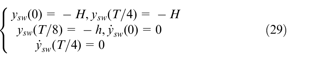
By introducing the boundary conditions into equations (27) and (28), the displacement equation in Y direction can be obtained as follows:
Given a set of parameters: H = 170√3 mm, h = (170√3-40) mm, S = 200 mm, T = 2 s. Figure 8 shows the trajectory of a single leg in one cycle.
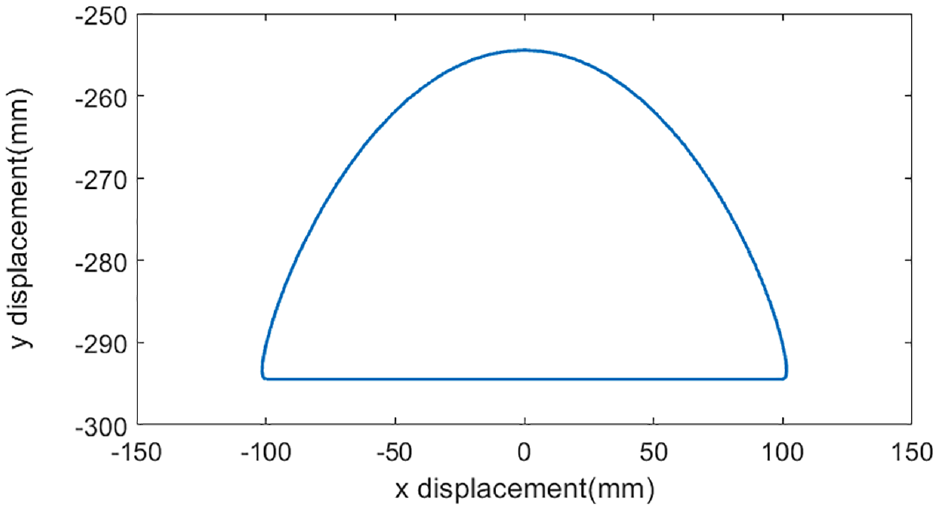
Single leg trajectory of robot.
Gait simulation of the quadruped robot
This paper focuses on the walk gait of the quadruped robot, which does not involve lateral and turning motion, so the hip joint is locked in the lateral swing degree of freedom, that is, θ1 = 0. Figure 9 builds a multi-body dynamics co-simulation system, in which the left half is the four leg control system of the quadruped robot, and the right half is the physical prototype model of the robot. In the single leg workspace, the driving curve of the hip and knee joint angular displacement required by the foot trajectory is obtained by using the inverse kinematics equation, and then the phase delay module is introduced to obtain the four leg driving curve with phase difference relationship. The multi-body dynamics module mainly realises the construction of the robot model and the constraints of the physical environment to ensure that it matches the real environment.
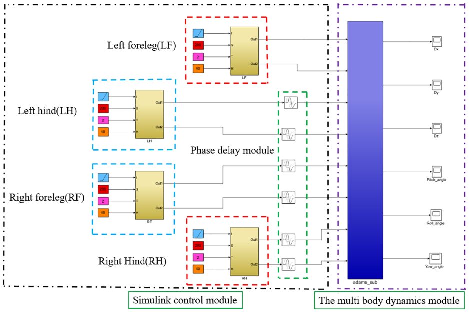
The multi-body dynamics co-imulation platform.
By Figure 10, it can be seen that the robot moves strictly according to the given phase relationship. The yellow part represents that the leg of the robot is in the swing phase, and the phase difference of each leg is 0.25, each leg moves in turn according to the planned gait, which proves the rationality of the mechanism design and the correctness of the planned static walking algorithm.
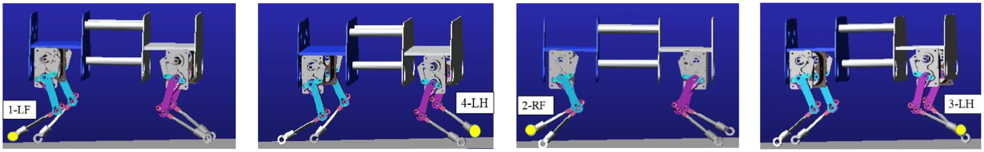
Phase sequence simulation diagram of quadruped gait (1-4-2-3).
In order to characterise the stability of the robot, the displacement of the centre of mass and the fluctuation of the velocity of the robot can be used as the measurement index. Figures 11 to 13 shows the variation of the displacement and the velocity of the centre of mass in the directions of x, y and z. From Figure 11, it can be seen that the maximum deviation of the centre of mass in the X axis direction is 49 mm, which shows that the robot can basically keep straight walking. Figure 12 shows that the maximum fluctuation of the centre of mass in the direction of Y axis is 35 mm and the maximum fluctuation rate is 5.98%, which proves that the robot can run smoothly. Figure 13 can obtain that the robot travels 1594 mm in 8 s, and its running speed is 0.196 m/s, which is close to the theoretical speed, the smaller error is caused by the slippage between the foot and the ground. On the whole, the quadruped robot can basically run stably along the straight line, and all the indexes meet the requirements.
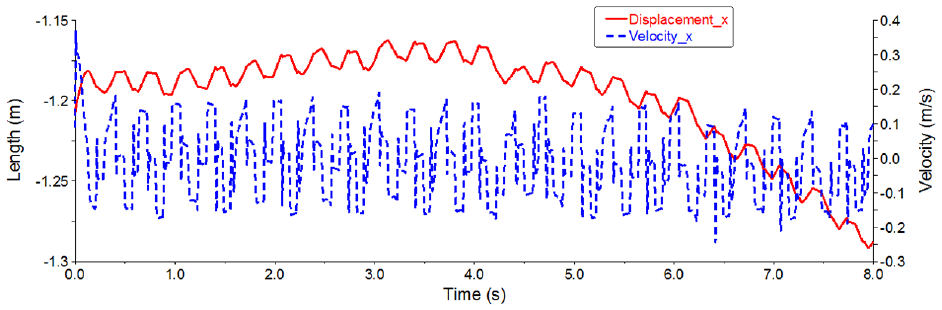
Displacement and velocity curves of robot centroid in x-axis direction.
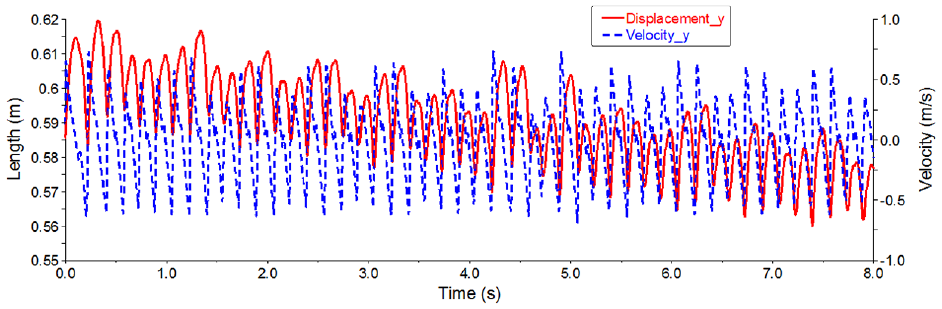
Displacement and velocity curves of robot centroid in y-axis direction.
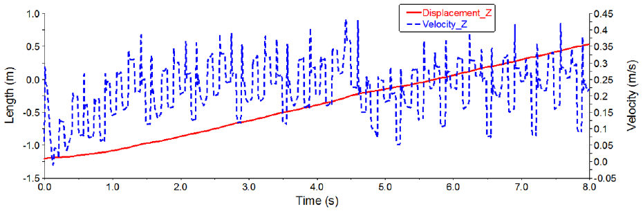
Displacement and velocity curves of robot centroid in z-axis direction.
Experiments and analysis
The single leg debugging lays the foundation for robot gait, and is also the precondition realising the algorithm. By debugging the single leg motor, the movement law the single leg can be obtained. In order to prevent the motor from blocking when the joint angle exceeds the limit position during the experiment, the debugging of the single leg structure should be completed before the whole machine is tested. According to the actual situation, three groups of DC motors and drivers are selected, all of them are connected with the main station and the slave station of EtherCAT through the network line. The controller is connected with the PC terminal by the network line, and the debugging and downloading of the control program are completed. It can be seen that the three motors can achieve specific motion in the range of rotation angle, Figure 14 shows the control process and debugging platform.
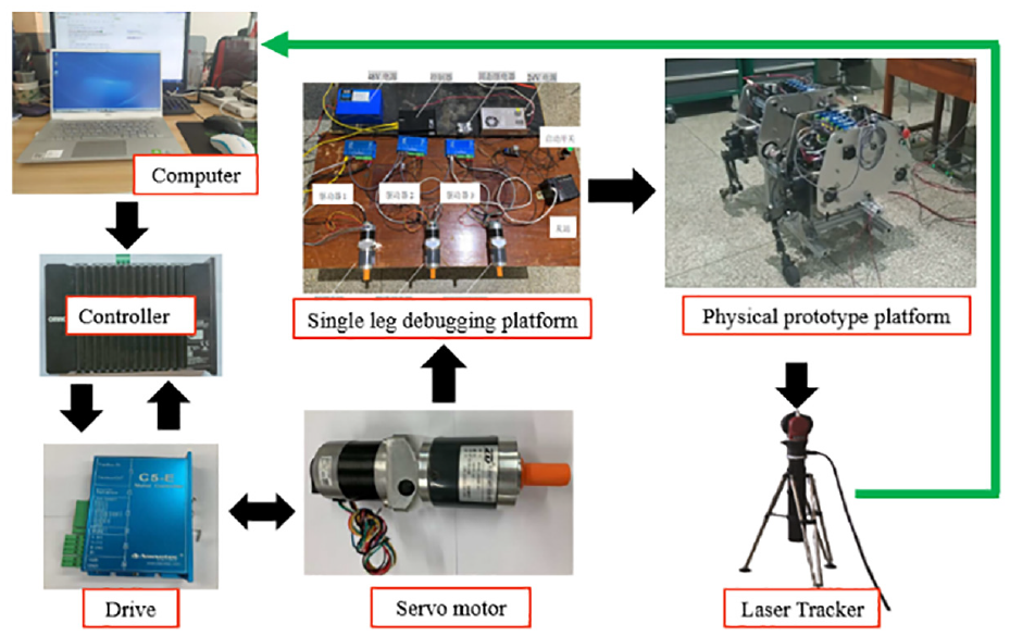
Experimental prototype platform.
The gait period is set to T = 2 s and the single leg step length is set to S = 200 mm. Setting the initial position and posture of the single leg as: θ1 = 0°, θ2 = −40°, θ3 = 80°. The curve of hip joint rotation angle θa and knee joint rotation angle θ2 can be obtained by inverse kinematics equation. Taking the right foreleg (RF) as an example, according to the curve of Figures 15 and 16 can see that hip joint rotation angle and knee joint rotation angle have sudden changes in speed and acceleration, which will lead to the instability of the quadruped robot.
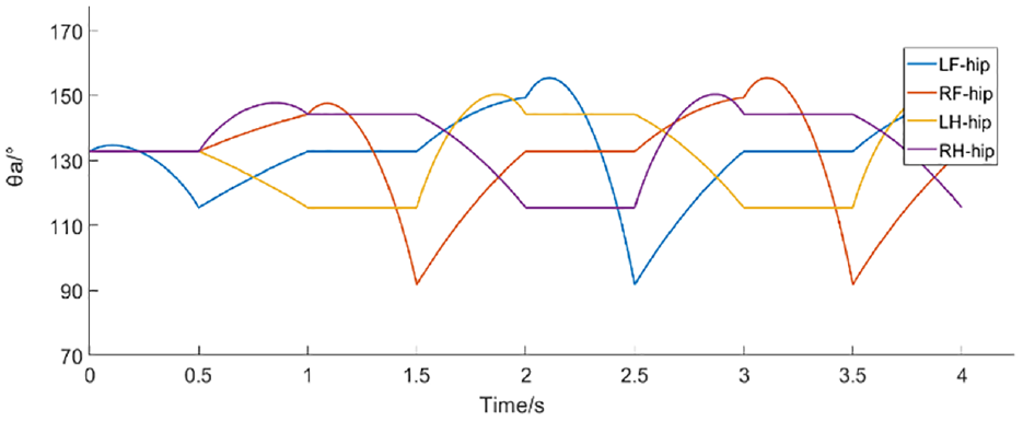
Changes of hip joint in right foreleg (RF).
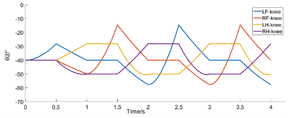
Changes of knee joint in right foreleg (RF).
In order to improve the stability of the running process and solve the chattering phenomenon in the motion process of the robot, the touching time of each leg of the robot is increased by 0.5 s, so that the duty cycle of the robot is changed from 0.75 to 0.875, which can improve the stability of the robot. The joint driving function of the robot is shown in Figures 17 and 18.
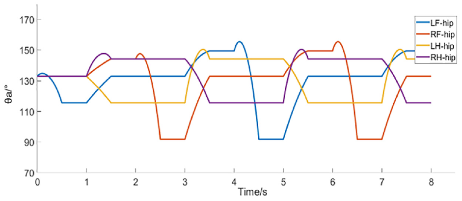
Changes of hip joint curve of right foreleg after adjustment (RF).
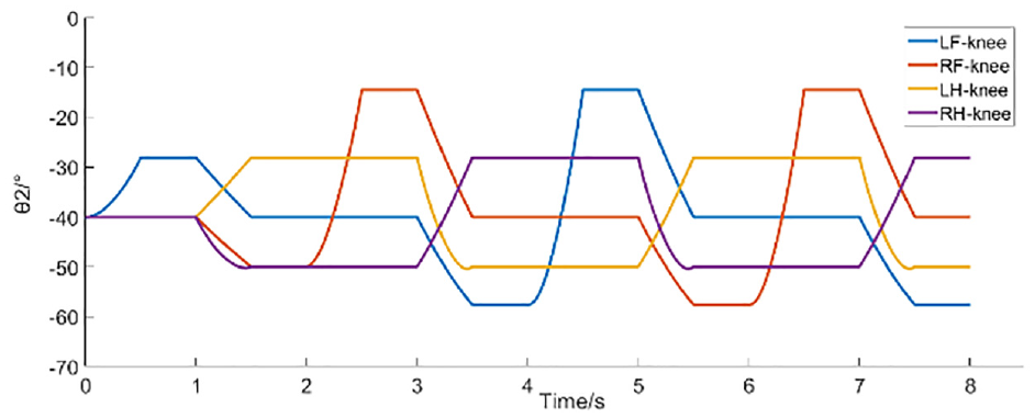
Changes of knee joint curve of right foreleg after adjustment (RF).
It can be seen from Figures 17 and 18 that increasing the duty cycle by extending the leg touchdown time can solve the problem of smooth joint angle and ensure the stability of robot motion. In order to observe the effect of single leg movement, the laser tracker is used to collect the trajectory points of the single leg in space, and the real-time graphics are drawn by the laser tracker software. Figure 19 shows the spatial sampling point diagram of the laser tracker. The trajectory is not as smooth as the ideal trajectory because of some errors in spatial sampling points, but it basically reflects the effect of robot foot movement, which proves the correctness of the proposed algorithm.
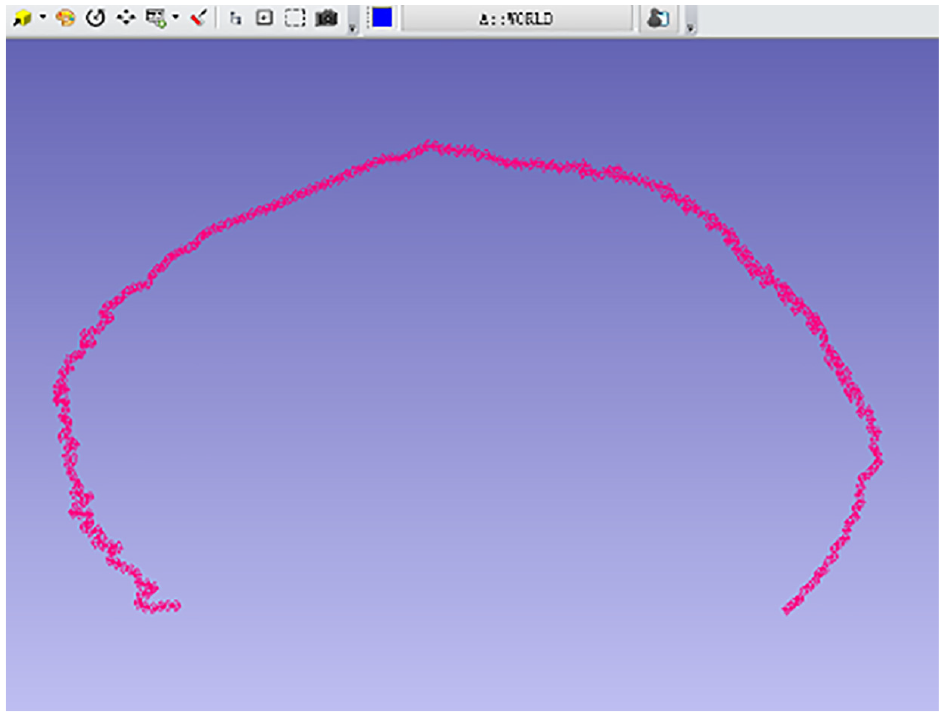
Space tracking effect of laser tracker.
Because the weight of electrical components and the materials used in the whole machine processing are not considered in the manufacturing process of the prototype, the fuselage is relatively heavy. In order to reduce the torque shortage caused by the self weight of the leg motor, a support frame is fixed under the fuselage, so that the weight of the robot is borne by the support frame, where the height of the support frame is less than the height of the single leg foot. Each leg moves once according to the phase sequence, so as to realise the operation of the whole machine. The driving function is used as the drive of the motor. The zero impact foot trajectory equation given in section 5 is introduced into the inverse kinematics equation of quadruped robot, and the joint driving functions of hip joint and knee joint can be obtained to realise the robot moving according to the predetermined trajectory. Figure 20 is the static walking experiment platform of the quadruped robot, which shows the complete trajectory of the swing phase and support phase of the right foreleg in a movement cycle. According to Figure 20, it can be seen that the robot can achieve a specific trajectory, which proves the correctness of the rationality of the mechanism design.
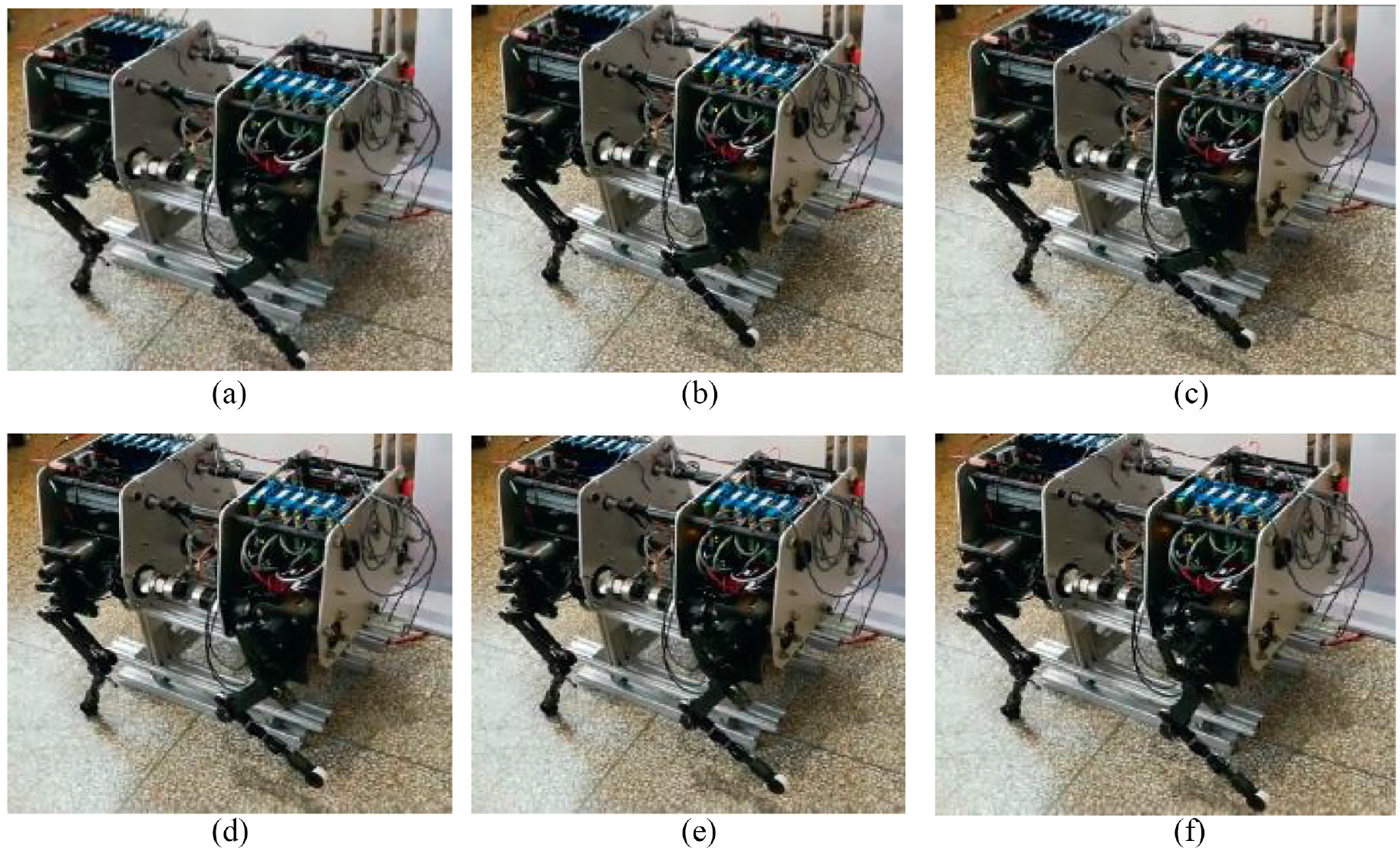
One cycle trajectory of single leg: (a) initial state, (b) T/16 period, (c) 2T/16 period, (d) 3T/16 period, (e) 4T/16 period and (f) 1 period.
Conclusion
In this article, a novel quadruped bionic robot with anti-parallelogram mechanism is proposed. Combined with the inverse kinematics equation and Monte Carlo method, the workspace of the single leg is obtained, and the conclusion that the workspace of the single leg is the largest when ∠CDE = 170° is obtained. The static stability of quadruped robot is discriminated, and the static gait of quadruped robot is planned. A co-simulation platform is built to achieve the effectiveness of the algorithm. The results show that the quadruped robot runs steadily according to the given gait of 1-4-2-3, and the fluctuation of the centre of mass in the X and Y directions is small, which proves that the robot can run smoothly. The duty cycle of the quadruped robot can be improved by increasing the support time between the foot and the ground. In this paper, the duty cycle is changed from 0.75 to 0.875, which not only solves the problem of tremble, but also increases the stability of robot motion. The zero impact foot trajectory is planned by polynomial, and the foot trajectory tracking diagram is obtained by laser tracker, which proves the correctness of foot trajectory planning. The experimental prototype platform is built, and the robot can run stably according to the planned gait, which proves the effectiveness of the proposed algorithm.
Footnotes
Declaration of conflicting interests
The author(s) declared no potential conflicts of interest with respect to the research, authorship, and/or publication of this article.
Funding
The author(s) disclosed receipt of the following financial support for the research, authorship, and/or publication of this article: This research was financially supported by National key R & D projects under Grant No. 2017YFC1702503 and the National Natural Science Foundation of China under Grant No. 51565021.