
Abstract
Industrial robots have advantages of large workspace, compact structure, and good flexibility, but the stiffness of the robot is relatively weak due to the compliance of reducers and its series structure. In this article, a five-degree-of-freedom robot with non-backlash driving is presented. A parallelogram structure with diagonal driven is used for robotic arms which is useful to improve the overall stiffness of the robot. First, the detailed structure of the robot is introduced, and the kinematic characteristics of the robot are analyzed. Second, a stiffness approximation method is proposed to evaluate the stiffness of the robot in the global workspace. The overall deformations under certain external loads which are composed of deflection deformations and stretching deformations are calculated based on the strain energy method and the properties of the components. The effectiveness of the approximation method used for evaluating the stiffness of the robot which has hybrid open- and closed-loop kinematic chains is verified through the finite element analysis results and the experimental results. Finally, the stiffness evaluation results show that the stiffness of the proposed robot is better than that of the industrial robot, which makes it more suitable for most of the industrial applications, such as handling, palletizing, and drilling.
Introduction
Industrial robots are being more widely used in a variety of industrial applications, such as handling, palletizing, and some machining applications, including milling, drilling, and friction stir welding (FSW) due to their advantages of large workspace, compact structure, good flexibility, and low cost compared with machine tools.1–4 The compliance of reducers and the elasticity of links make the stiffness of the industrial robots worse; the stiffness of a large six-degree-of-freedom (DOF) industrial robot is usually lower than 1 N/µm; however, the stiffness of a standard computer numerical control (CNC) machine tool is usually higher than 50 N/µm. 5 Due to the relatively low stiffness, industrial robots always suffered from static and dynamical deformations or chatter vibrations induced by external forces applied on the end-effector during the machining process. 2 The deformation of the robot makes the tool deviate from the ideal position which leads to poor machining quality and inferior production efficiency. 3 The stiffness of the robot mainly depends on the following factors: (1) geometric and material properties of the links, (2) actuators and transmission elements, and (3) robot postures. In fact, for a standard industrial robot, the first two factors are almost impossible to change, and hence its stiffness is mainly affected by the robot posture. Therefore, the stiffness of the robot can only be increased by posture optimization. However, the improvement for the robot stiffness is also limited only by posture optimization.
Recently, relevant research literatures on the improvement of robot accuracy by improving the robot structure are less. Wu et al. 6 designed a heavy FSW robot for large-scale complex surface welding, and the test results show that the robot has high stiffness and meets the requirements of welding precision. Palpacelli 7 put forward an auxiliary cable-driven system on the end-effector of the robot, which is used to increase the stiffness and the static performance of the robot. Maldonado-Echegoyen et al. 8 even designed parallel robots to improve the machining precision.
In addition to compliance, backlash is also one of the influences on the accuracy of the robot.9,10 Especially, when the directions of the external loads change rapidly or the robot undergoes a fast movement, vibrations and resonant phenomenon caused by gear backlash will appear. 11 Several methods based on backlash feedforward compensation were proposed to minimize the effect of the backlash.12,13 Dual-motor drive system with anti-backlash control is widely used in parallel manipulators, pendulums, and large-size turntables to eliminate the transmission backlash;14–16 however, it is less used in robots.
Stiffness has an influence on deformations of the robot under external loads which inevitably affect the accuracy of robot positioning repeatability.17,18 Soares Júnior et al. 19 presented a matrix structural analysis approach to calculate the stiffness of the multi-body system. A Rezaei et al. 20 proposed that the robot was equivalent to distributed systems, and the stiffness of a spatial 3-PSP parallel structure was obtained through the strain energy calculation of the main components. Rezaei and Akbarzadeh 21 used strain energy and Castigliano’s theorem to establish the stiffness model of the parallel manipulators.
In this article, a novel robotic arm which can be used for industrial applications is presented. Unlike traditional industrial robots, the robotic big arm and small arm proposed have a parallelogram structure with diagonal driven by an electric cylinder, which form closed-loop kinematic chains. The big arm and small arm are connected as a series structure with an open-loop kinematic chain. An approximation method based on the strain energy and the properties of the components is put forward to obtain the robot stiffness. The approximation method is suitable for stiffness evaluation of the robot which has hybrid open- and closed-loop kinematic chains. Then, the stiffness of the robot at four positions is calculated, and the results are verified compared with the finite element analysis (FEA) results and the experimental results. Finally, the stiffness characteristics of the robot in the main working area are presented to show its potential for industrial applications.
Description of the robot structure
Industrial robots usually have four or six DOFs, and a great number of machining operations such as drilling and milling only require five DOFs, where three DOFs are used to locate the tool center point (TCP) and another two DOFs are used to orient the tool axis. The robot presented has five DOFs, with one freedom for the base, two freedoms for the robotic arm, and two freedoms for the robot wrist, as shown in Figure 1.

Structure of the five-DOF robot.
The robot base is composed of two servo motors, a worm gear inside the base, and a rotary column. Two servo motors are symmetrically arranged on both the sides of the worm gear, which are used to drive the worm gear together, and the column is connected to the worm gear. The worm gear system can replace gear reducers because of its large transmission ratio. In addition, driving ability and response characteristics of rotating can be promoted by dual-motor drive, and at the same time, the backlash of the worm transmission chain can be eliminated by implementing anti-backlash control method, which can improve the positioning accuracy of the rotary motion.
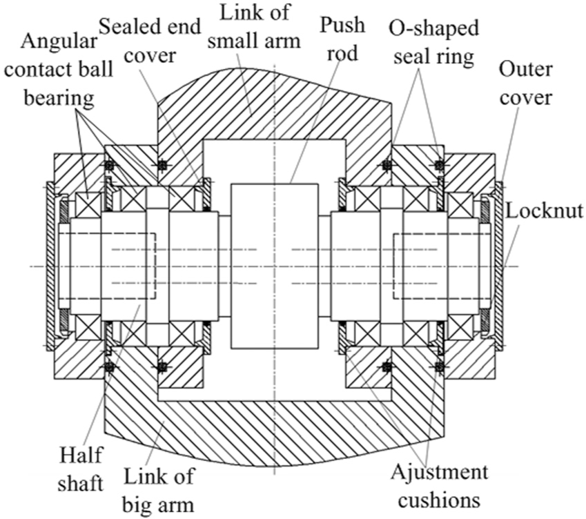
A parallelogram structure with diagonal driven is used in both big and small arms of the robot to increase the robot stiffness. The robotic arm can rotate around the column, and the linkage motions of the big arm and the small arm are achieved through controlling the expansion length of electric cylinders in arms. The structure of the electric cylinder is shown in Figure 1. The lead screw is driven by a servo motor that is installed on the rear of the cylinder body, and a rotary motion of the lead screw translates into a linear motion of the nut by limiting the rotary motion of the nut. Double nuts with preload are used in ball screw to remove the reverse backlash, which are often used in fine feed systems. Besides, the ball screw works under interference fit condition when it is preloaded, which makes the stiffness of ball screw increased. 22 In addition, four angular contact thrust ball bearings with moderate preload are used to support the lead screw.
The robot wrist has two freedoms of pitching and tilting, which are used for adjusting the pose of the end-effector. The robot wrist is designed based on differential drive principle. The wrist is mainly composed of three parts, including first differential input, second differential input, and the differential output. The torques supplied by motors are transmitted to bevel gears via the worm gear system. Therefore, the motions of pitching and tilting are achieved by controlling the input angles of servo motors. The transmission structure acting as master drive is used to bearing external loads, and the slave drive is used to eliminate transmission backlash.
Multiple passive joints are formed at the intersection of robot links. The matched angular contact bearings in passive joints are installed with certain preload to increase joints’ stiffness and eliminate the clearance of the robot joints, and the connecting shafts in passive joints are designed with sufficient rigidity avoiding affecting the overall stiffness of the robot.
According to the environment of industrial applications, some necessary protections are considered for the robot design. The contact regions between the big arm and the small arm are sealed by sealing rings, and the outer of joints are sealed with end covers, so as to realize the protection for inner bearings. Also, the push rods of electric cylinders can be fully protected by wrinkle protective covers.
Kinematic analysis of robotic arms
Position analysis
The robot structure can be simplified as two serial connected parallelograms, and the electric cylinders are simplified as the diagonal of the parallelogram, as shown in Figure 2. The length of long links in arms is 1000 mm, and the length of short links is 460 mm. The cross sections of links are rectangle, in which the width of the long links in the small arms is 220 mm, and in the big arm it is 300 mm; the thickness of long links in the small arm is 60 mm, while in the big arm it is 70 mm. The motion angle β1 varies from −30° to 65°, and angle β3 varies from 0° to −65°; the robotic arm can rotate around the column from −180° to 180°.

Parameters of the robot.
The joint F is set as the origin of the base coordinate; therefore, the position coordinates of the wrist joint G can be expressed as

where LDF and LAD denote the length of long links of the big arm and the small arm, respectively, LGI and LAI represent the lengths between points G and I and points A point I, and β1 and β2 are the angles between links.
According to equation (1), the workspace of the robotic arm is calculated based on Monte Carlo methods, as shown in Figure 3. The robot can reach to 2280 mm in horizontal direction, which is close to the reachable distance of the industrial robot with similar links’ sizes, and the workspace of the robot is a regular sector shape which makes machining tasks convenient. From a practical point of view, a regular area of rectangular shape with 600 mm × 800 mm that is defined as the main working area can be planed from the sector workspace, which is surrounded by points from P1 to P4.

Workspace of the robot.
The position of the robot in the x–o–z plane can be changed by adjusting the length of electric cylinders, which can be calculated as follows
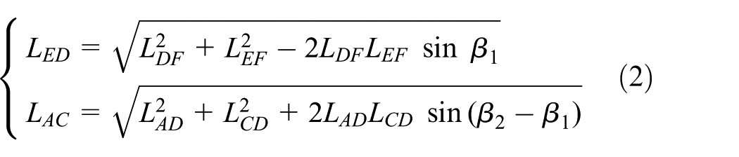
where LEF and LCD denote the length of short links, respectively.
The length of the big arm cylinder between connected joints varies from 626 to 1293 mm, and the length of the cylinder in the small arm varies from 1101 to 1425 mm.
Velocity analysis
The velocity of the robotic arm depends on expansion speeds of the electric cylinders. Accordingly, angular velocities of arms are obtained

where vx and vz denote the linear velocities in x- and z-directions, respectively.
The velocities of cylinders are calculated based on the method of complex vector. Closed vector polygons are established in the triangles of ACD and EFD. The closed vector position equations are represented as complex vector forms, which are shown as follows
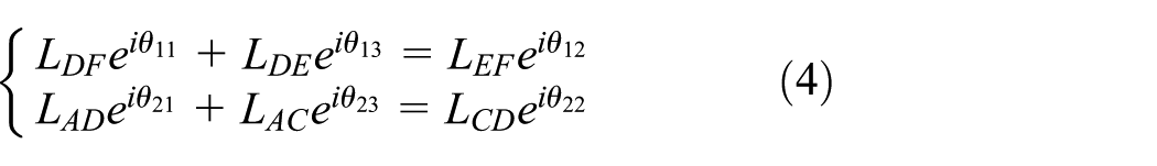
where θ1j and θ2j (j = 1, 2, 3) denote angles between arms.
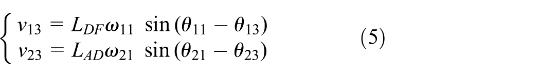
Therefore, the following expansion speeds v13 and v23 of cylinders are obtained based on equation (5)
Stiffness modeling and calculation
Stiffness modeling method of the robot
The robotic arm has a hybrid structure with open- and closed-loop chains which is different from the structure of traditional industrial robots. The stiffness calculation method for industrial robots is not suitable for this kind of robotic arm. Therefore, an approximation method for stiffness calculation is proposed in this section.
According to the structure of the robotic arm, the long links of the parallelogram and electric cylinders can be equivalent to elastic bodies, while the short links are assumed to be rigid bodies; the flexible model of the robot is shown in Figure 4. Angular contact ball bearings with moderate preload are used in each robot joints to increase the stiffness of bearings and eliminate the clearance of robot joints, as shown in Figure 5. Therefore, clearances are not considered in the numerical model, and the deformation is only caused by the deformation of the robot structure. The relative deformations of robot joints can be calculated based on strain energy method and Castigliano’s theorem. The robot wrist is driven by bevel gears and worm gears which have high stiffness, and the wrist is fixed at the end of the robot that has little effect on the deformations of the end-effector, so the wrist is assumed to be a rigid body for stiffness analysis.

Flexible model of the robotic arm.
Assembly drawing for the robotic joint.
Considering that in machining applications, the robot is mainly affected by cutting forces rather than cutting moments, while the magnitude of the rotation deformation is negligible relative to the translational deformation. 23 Therefore, the external forces applied on the end-effector can be expressed as a matrix

The relationship between external force

where δ

where

The deformations of joints in the plane of x-o-z can be calculated based on equation (10)

where U represents the strain energy of the joint; F denotes the force of links represented as subscripts; K denotes the equivalent stiffness of the electric cylinder; Fx,z denotes the additional force applied on the joint along x- and z-axes, respectively. E denotes the elastic modulus, 210 GPa; l denotes the length of the link; A denotes the cross-sectional area of the link

where b and h denote the width and the thickness of the cross section, respectively.
In addition, the deformations of joints in the plane of x-o-y can be calculated based on equation (12)

where I represents the moment inertia of the link.
Based on the analysis above, the deformations of robot joints can be obtained by numerical calculation based on strain energy method. Therefore, the total deformations can be obtained based on the joints’ deformations. The flowchart for approximation method used for calculating the total deformations is shown in Figure 6. According to the external forces and deformations, the directional stiffness of the robot can be calculated based on equations (8) and (9).
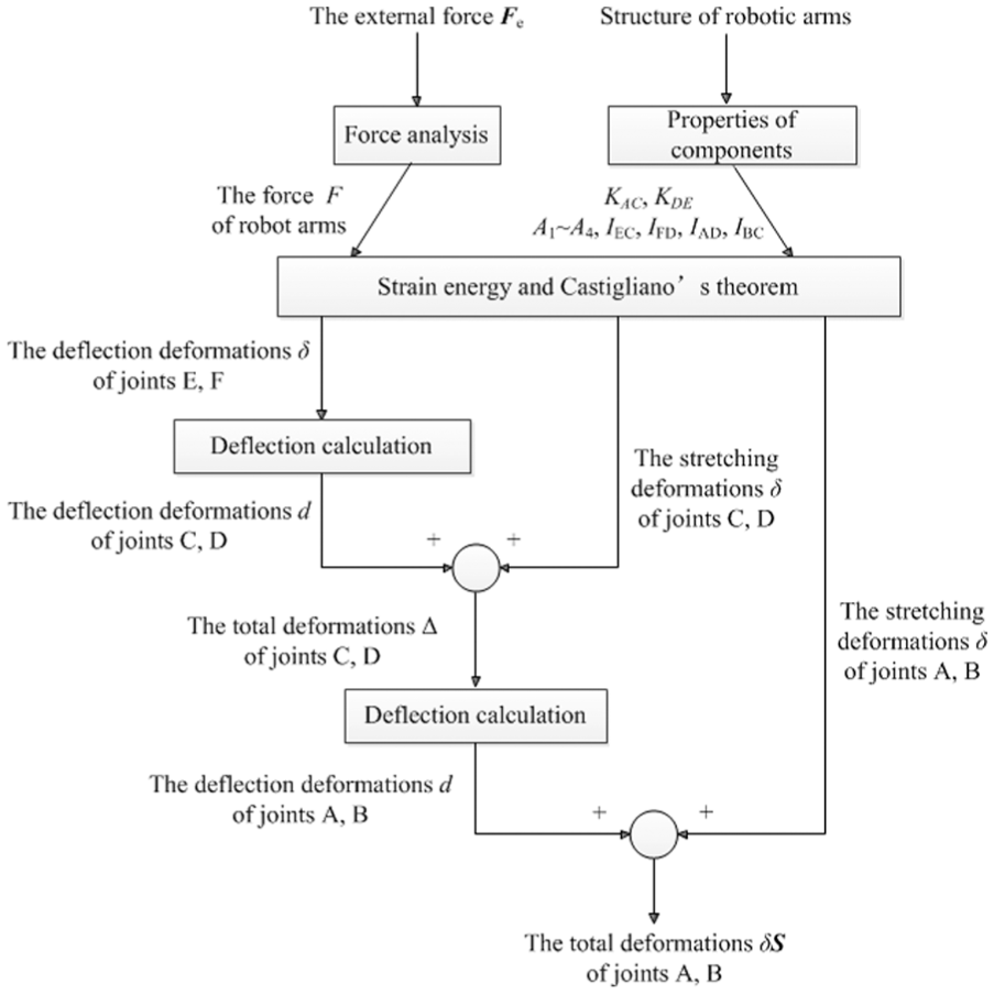
Flowchart for the approximation calculation method.
Simulation verification by FEA
Considering the axial load, installation space, and stability of the screw comprehensively, the nominal model BNFN 4506A-7.5 of THK bearing screw is selected in the small arm. The stiffness of the double screw nuts is 2210 N/µm according to the production manual. 24 In addition, four angular contact thrust ball bearings with model 40TAC90B of NSK are used for supporting the lead screw, and the axial stiffness of the bearings is about 2650 N/µm with standard preload according to the production manual. 25 The rod stiffness of small arm cylinder is 1416 N/µm. Similarly, in the big arm cylinder, the nominal model BNFN 5008A-7.5 bearing screw is selected. The stiffness of the double screw nuts is 2470 N/µm. Four angular contact thrust ball bearings with model 45TAC100B of NSK are used, and the axial stiffness of the bearings is about 3000 N/µm with standard preload. The rod stiffness of big arm cylinder is 1556 N/µm. The equivalent stiffness K of the electric cylinders can be obtained as

where KR denotes the rod stiffness, KN denotes the screw nut stiffness, KS denotes the screw stiffness, and KB denotes the bearing stiffness.
Figure 7 shows the stiffness of cylinders accompanied with different arm angles calculated based on equation (13).

Stiffness of electric cylinders: (a) big arm and (b) small arm.
FEA is usually used for calculating the robot deformation; however, the robot model needs to be imported again when the posture of the robot changed; in addition, the contact parameters between connected components need to be set again which increases time consumption. So FEA is not convenient to obtain robot deformations in the global workspace. However, FEA can provide relatively reliable and accurate results for deformation analysis under certain loads; it is often used to verify the correctness of theoretical results.26–28
Four positions marked with point Pi (i = 1–4) are selected to verify the stiffness calculation results. The assembly model of the robot is imported into ANSYS Workbench, and the boundary conditions and loads of the robot remain unchanged during computation, where the base of the robot is grounded and the external force is applied on the flange center of the wrist. The materials of the robot structures are properly defined as elastic bodies before the simulation process, the material of the base is defined as nodular cast iron QT500, the material of robotic arms is defined as carbon steel Q235, and the material of electric cylinders is defined as aluminum alloy Z1110. The properties of the materials are shown in Table 1. The screw and the screw nut in the electric cylinders are simplified as a shaft and a cylinder with a fit hole, respectively, and the contact region between the screw and the screw nut is defined as “bonded” in the FEA model. The equivalent stiffness of cylinders in FEA is adjusted to identical with the stiffness results calculated using equation (13) by adjusting the area of the contact region. The contact conditions between links at the joints are defined as “no separation.” An automatic mesh control method with both tetrahedrons and hex meshing is used to divide the robot structure into 115,663 elements.
Material properties of the robot structures.

To obtain the stiffness in x-direction, an external force in x-direction applied on the center of the flange is expressed as

The results of the deformations in x-direction using FEA software are shown in Figure 8. The wireframe in the FEA represents the undeformed positions of the robot.

Deformations in x-direction obtained by FEA: (a) P1 position, (b) P2 position, (c) P3 position, and (d) P4 position.
An external force in y-direction applied on the center of the flange is expressed as

The results of the deformations in y-direction using FEA software are shown in Figure 9. The undeformed position overlaps the deformed position from this point of view.

Deformations in y-direction obtained by FEA: (a) P1 position, (b) P2 position, (c) P3 position, and (d) P4 position.
Likewise, the other external force in z-direction applied on the flange is expressed as

The results of the deformations in z-direction using FEA are shown in Figure 10.

Deformations in z-direction obtained by FEA: (a) P1 position, (b) P2 position, (c) P3 position, and (d) P4 position.
The directional stiffness results using the approximation method are shown in Table 2, which includes the results of the FEA models and their difference. The results of the approximation method are little bigger than FEA results, because the wrist and the shafts are equivalent to rigid bodies for the approximation calculation. The results of approximation method closely follow the results of FEA which verify the correctness of the approximation method.
Stiffness analysis results of the robot.
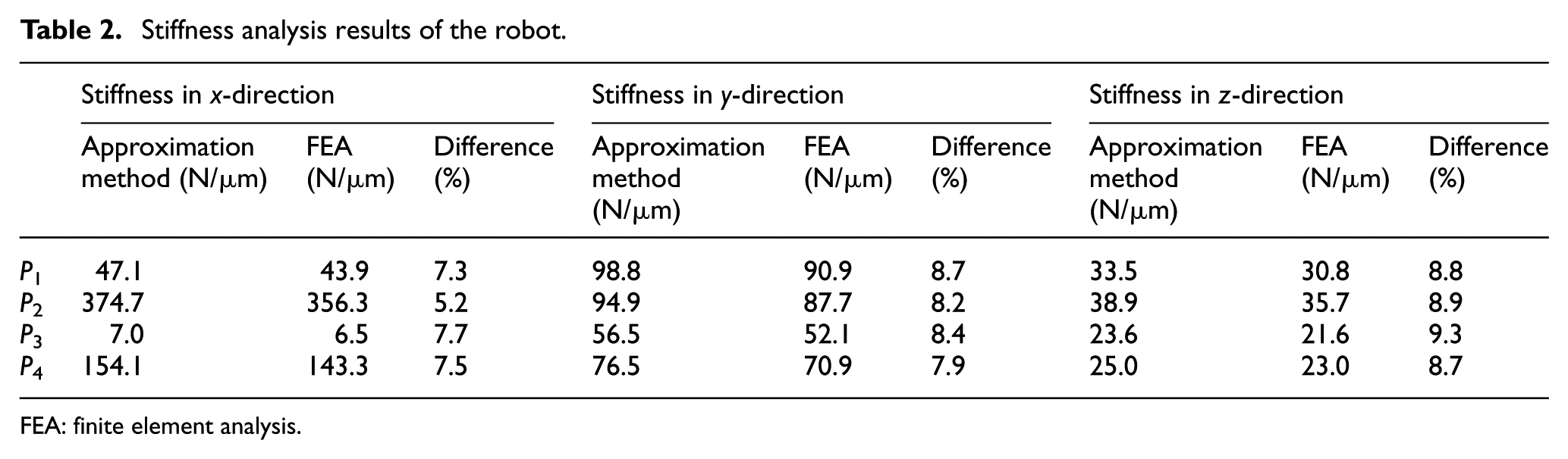
FEA: finite element analysis.
Experimental verification
To further verify the effectiveness of the approximation method, a small-scale robot prototype is established. The long link and short link of the parallelogram structure in robotic arms are 360 and 240 mm, respectively, and the material of the links is 6061 aluminum alloy. External loads are applied on the end of the robot, and the corresponding deformations are measured using the dial indicator to obtain the stiffness of the robot. A jack is used to produce an external load, and the dynamometer between the jack and the robot is used to measure the external force. The experimental device for measuring the stiffness of the robotic arm is shown in Figure 11(a). The method for measuring the stiffness of the electric cylinders is the same as the method for measuring the stiffness of the robotic arm, and the measuring device is shown in Figure 11(b).

Stiffness measurement devices for the robotic arm and electric cylinders: (a) robotic arm and (b) electric cylinder.
The experimental stiffness results at four positions (N1–N4) are selected to verify the correctness of the approximation method. The coordinates of the four positions are as follows: N1(650, 50), N2(700, 50), N3(650, −50), and N4(700,−50). The stiffness of the big arm cylinder and the small arm cylinder is 1.25 and 0.84 N/µm, respectively, at N1 position; the stiffness of the big arm cylinder and the small arm cylinder is 1.07 and 0.87 N/µm, respectively, at N2 position; the stiffness of the big arm cylinder and the small arm cylinder is 1.13 and 0.77 N/µm, respectively, at N3 position; and the stiffness of the big arm cylinder and the small arm cylinder is 1.02 and 0.82 N/µm, respectively, at N4 position. The stiffness results calculated using the approximation method and measured in the experiment are shown in Table 3. The approximation results are close to the experimental results which verify the effectiveness of the approximation method. Therefore, the method can be used to evaluate the robot deformation under external load and calculate the stiffness of the robot which has hybrid open- and closed-loop kinematic chains.
Stiffness results of the robot prototype using the approximation method and the experiment.

In addition, the small size of the parallelogram frame restricts the size of electric cylinders in the prototype. However, the stiffness of small-scale electric cylinders is weak (about 1 N/µm), which makes the overall stiffness of the robot prototype weak. The experimental results of the robot prototype cannot reflect the high stiffness of the robot structure, and they are only used to verify the effectiveness of the approximation method.
Results and discussions
Based on the analysis results above, we can use the approximation method to calculate the robot stiffness in the workspace conveniently. Within the working area in the workspace, the directional stiffness of the robot in the rectangle area surrounded by points from P1 to P4 is calculated based on the approximation method, which is shown in Figure 12. The directional stiffness in x-direction varies from 7 to 375 N/µm; the directional stiffness in y-direction varies from 57 to 99 N/µm; and the directional stiffness in z-direction varies from 24 to 39 N/µm. In addition, the weight of the robot evaluated in the SolidWorks is about 2000 kg, which is similar to the industrial robot with a similar size.

Directional stiffness of the robot. Pi(i=1~4) represent the points in the workspace described in Figure 3.
According to the directional stiffness results calculated above, we can conclude the following conclusions:
The directional stiffness of the proposed robot is better than that of industrial robots in which the stiffness is only several newtons per micrometers.4,29 It is also feasible to change the stiffness of the robot within a reasonable scope by adjusting the stiffness of links.
The directional stiffness of the robot with unfolded status is better than that in contraction status, which is conductive to reduce the robot deformation during large radius operations.
Conclusion
In this article, we proposed a novel robotic arm which has parallelogram structures, and the robotic arm is driven by electric cylinders in the diagonal direction of the parallelogram. The reverse backlash of the lead screws in electric cylinders can be eliminated using double nuts with preload. Besides, the dual-motor anti-backlash control method can be implemented to worm gears in the base and the wrist so that the transmission backlash of the robot can be eliminated.
A stiffness approximation method based on the strain energy and the properties of the components is put forward to evaluate the robot stiffness. The effectiveness of the approximation method is validated through the FEA results and the experimental results. The stiffness approximation method will provide reliable results within the global workspace which is suitable for calculating the stiffness of the robot with hybrid open- and closed-loop kinematic chains.
The stiffness calculation results of the proposed robot show that the directional stiffness is obviously superior to that of the industrial robot. The stiffness in some area of the workspace is equal to the stiffness of a machine tool. Meanwhile, the stiffness of unfolded status is better than contraction status which is conductive to improve the load capability of the robot.
Footnotes
Handling Editor: Jan Torgersen
Declaration of conflicting interests
The author(s) declared no potential conflicts of interest with respect to the research, authorship, and/or publication of this article.
Funding
The author(s) disclosed receipt of the following financial support for the research, authorship, and/or publication of this article: This work was supported by the National Natural Science Foundation of China (grant no. 51575092), the National Key Research and Development Program of China (grant no. 2017YBF1300901), and the Collaborative Innovation Center of Major Machine Manufacturing in Liaoning.