
Abstract
The paper identifies the signals acting on hydraulic valves. They were divided into a group of signals that are intentional and those that interfere with the correct operation of hydraulic valves. It was reported that machines and devices equipped with hydraulic systems are a source of vibrations in a wide frequency range. The vibrations generated by the machine affect the hydraulic valves. Particular attention was focused on the effect of external mechanical vibrations on changes in the amplitude-and-frequency spectrum of pressure pulsations in a hydraulic system, in which a single-stage relief valve was vibrated. The theoretical description of the oscillating valve was modified by taking into account the kinematic forcing by a periodic function. The results of own experimental tests are also presented.
Introduction
Machines and equipment fitted with hydraulic systems are both sources and receivers of mechanical vibrations across a wide frequency spectrum.1,2 On the other hand, the signals reaching the hydraulic valve can be divided into intended signals, such as those that control the operation of the valve, and unintended signals that interfere with the proper operation of the valve. The latter group also includes mechanical vibrations. According to Guodong et al. 3 and Stosiak et al., 4 the mechanical vibrations of the machine, particularly its frame, are transmitted to all elements mounted on the machine frame, as well as to the surrounding environment and the machine operator (Figure 1(a) illustrates the vibration conditions of a machine with frame). Figure 1(b) shows an example of the amplitude-and-frequency spectrum of vibrations of the forklift frame, with the engine running at 800 rpm under no load.

Vibration problem in the machine: (a) forklift vibration conditions and (b) vibration spectrum of the forklift’s frame (vertical direction of vibration).
From the perspective of the hydraulic system’s impact on the environment and its proper performance of the assigned functions, it is important to limit or completely eliminate pressure pulsations within the hydraulic system. 5 According to Jiaxing et al., 6 the latter task is very difficult and usually impossible in typical hydraulic systems of working machines. Therefore, to reduce pressure pulsation in the hydraulic system, it is essential to understand their causes. One important cause of pressure pulsations is the pulsation of the displacement pump output. 7 The pulsation of the displacement pump output is caused by the kinematics of the pump’s displacement elements (vanes, pistons, teeth). Its frequency typically ranges from 150 to 375 Hz, and the value of the first harmonic in the spectrum depends on the number of displacement elements and the speed of the pump drive shaft.8,9 Figure 2(a) shows the instantaneous efficiency of the V3-63 vane pump at a drive shaft speed of 1800 rpm. The waveform was obtained through numerical calculations performed in the MATLAB Simulink environment.

Vibration results charts: (a) output pulsation of the V3-63 vane pump from Ponar-Wadowice at a rotational speed of n = 1800 rpm and (b) transmittance module of the hydraulic system as a function of hydraulic line length and the excitation frequency.
Another cause of pressure pulsations in the hydraulic system is the wave phenomena associated with the presence of a long hydraulic line.10,11 Local hydraulic resonance can occur in a hydraulic conduit,11,12 specifically a long hydraulic line, if the following condition is met:
The aforementioned mechanical vibrations that accompany the operation of each machine serve as excitations for hydraulic valves such as: manifolds, maximum valves, non-return valves, etc. The literature points out the problem of vibrations in hydraulic valves.13,14 These excitations cause numerous undesirable effects, such as inducing vibrations in the control elements of hydraulic valves.15–17 The control elements of valves, such as the spool (in hydraulic valves) or the poppet (in hydraulic relief valves), are responsible for fixing the area of the flow gap in the valve, 18 and thus for throttling the flowing fluid.19,20 When the control element vibrates, the area of the throttling gap changes, resulting in the formation of additional components in the pressure pulsation spectrum of the hydraulic system, in which a valve with a vibrating control element operates, for example, a relief valve with a vibrating poppet.
In this study, a modified model of a single-stage relief valve is proposed. The proposed mathematical model takes into account external mechanical vibrations. These vibrations were incorporated into the mathematical model in the form of a harmonic function as a kinematic forcing with a fixed amplitude and frequency. In addition, the proposed model, when further modified to describe a two-mass system, can be used to assess the effectiveness of a passive vibration isolation system.
Mathematical modeling of hydraulic relief valve vibration
The load analysis of the relief valve poppet can begin with steady-state operating conditions. The following forces act on the valve poppet: the force (F) from the static pressure on the active surface of the poppet; the force (F sz ) from the pressure in the gap; the spring stiffness force (F s ); the hydrodynamic force (F d ) and the force of viscous friction in the valve gap (F t ). The force of static pressure (hydrostatic thrust) exerted on the active surface of the poppet is:

The force F sz depends mainly on the thickness of the gap in the valve and the length of the valve seat formation l. The value of this force decreases as the poppet elevation increases, reaching its maximum value at the moment the valve opens, that is, when x = 0, and can be given using the following formula:

The force of the stiffness of the valve spring is given by the equation:

where, k s – spring rate; x0– initial spring deflection.
The constant component of the hydrodynamic force, which is a result of the stream momentum change in the valve gap, 21 can be determined from the following formula:

where, ρ– density of the flowing fluid; Q– flow rate of the fluid through the valve; v1– average flow velocity of the fluid at the valve inlet; v2– average flow velocity of the fluid in the valve seat, Υ– outlet angle of the liquid jet in the valve plug-seat gap.
The direction of this force is parallel to the force from the spring stiffness (for poppets with a positive opening angle). For displacements where x > x1, the dependence between this force and the poppet displacement can be assumed to be linear. However, the value of the viscous frictional force in the gap is significantly lower than the other forces, so it can be omitted from the considerations. Thus, the poppet equilibrium equation for the steady operation of the valve takes following the form:

If the hydraulic relief valve is rigidly mounted on an oscillating machine frame during real operation. The valve operates in a quasi-steady state, as it is continuously exposed to kinematic excitations. There are viscoelastic constraints between the valve poppet and the vibrating valve body. Under these conditions, an equation of equilibrium can be written for forces acting on the valve poppet, which begins to oscillate due to external kinematic excitation, the form of which can be given as a harmonic function. The quasi-steady condition described includes the period during which the poppet oscillates around the equilibrium position, resulting from the balance of forces acting on it. The poppet is lifted to a certain height, and it is assumed that the poppet does not collide with the valve seat, which would interfere with the oscillation of the poppet.
This state can be described by two ordinary differential equations: the equilibrium equation of the forces acting on the poppet 22 and the equation of the balance of flow rate through the valve. In addition, the equilibrium equation of the forces acting on the poppet is supplemented by terms related to the kinematic excitation acting on the open relief valve:


where, c sz – stiffness of the pressure distribution in the gap; c s – spring stiffness (related to the valve spring force); c d – hydrodynamic stiffness (related to the hydrodynamic force in the valve).
Figure 3 shows the system of forces acting on the poppet in a quasi-steady state, that is, when the valve is open and its body is affected by external mechanical vibrations.

Load on the poppet of the relief valve subjected to external mechanical vibrations: F– liquid pressure force on the active surface; F sz – pressure forces in the gap; F s – forces and stiffness of the valve spring; F d – hydrodynamic force; l– generatrix length; x– poppet displacement; Θ– stream outflow angle; α– half of the poppet cone opening angle; d– valve seat diameter; m– poppet mass; v1– velocity of the incoming fluid stream; v2– velocity of the outgoing fluid stream; w(t) – kinematic excitation (vibrations of relief valve body).
The first term of equation (6) represents the inertia force of the poppet-and-spring system. The mass of the poppet is assumed to be 1 and 1/3 the mass of the spring. The second term represents the friction force of the viscous poppet, which is proportional to the relative velocity. The third term of equation (6) is related to the equivalent stiffness c z of all forces acting on the poppet. The value of the c z coefficient is determined from the valve’s static characteristic within its linear range.
The second equation defines the flow balance through the valve:

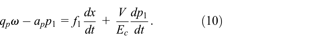
where, Q p – flow rate of the stream supplied to the valve; Q av – flow rate of leaks at the pump; f1·dx/dt– flow rate caused by poppet displacement; V/E c ·(dp1/dt) – flow rate caused by the capacitance in the line between the source and the relief valve; q– unit output of the pump; ω– angular velocity of the pump drive shaft; E c – Bulk modulus.
In formulating the above–presented equations, it is assumed that there is no flow through the safety valve.
The coefficients of the mathematical model described by equations (6) and (9) were parameterized using Mathematica. Afterward, the system of equations was solved numerically to obtain time waveforms of the valve poppet vibrations and pressure pulsations before the valve. The calculations were performed for different frequencies of external vibrations: 15; 20 and 40 Hz. For numerical calculations, the real conditions of kinematic excitation occurring on the test bench were assumed: at a frequency of 15 Hz, the vibration amplitude was w0(15) = 1.12 × 10⁻³ m; at 20 Hz, the vibration amplitude was w0(20) = 0.65 × 10⁻³ m; and at 40 Hz, the vibration amplitude was w0(40) = 0.18 × 10⁻³ m. The spectrum of pressure pulsations with a vibrating relief valve at a specified frequency of external mechanical vibrations is presented in Figure 4.

Spectrum of pressure pulsations with a vibrating relief valve: (a) frequency of external mechanical vibrations, f = 15 Hz, (b) frequency of external mechanical vibrations, f = 20 Hz, and (c) frequency of external mechanical vibrations, f = 40 Hz.
The solution to the system of equations (6) and (9) also provides the waveform of valve poppet vibrations. The results of the poppet vibrations, presented as an amplitude spectrum, are shown in Figure 5.

Spectrum of vibrations of the relief valve poppet: (a) frequency of external mechanical vibrations, f = 15 Hz, (b) frequency of external mechanical vibrations, f = 20 Hz, and (c) frequency of external mechanical vibrations, f = 40 Hz.
The spectrum of pressure pulsations presented in Figure 4 results from the vibrations of the relief valve poppet. The component frequencies of the pressure pulsation spectrum correspond to the frequency of the external mechanical vibrations. Additionally, the actual pressure pulsation spectrum includes a component corresponding to the pulsation of the displacement pump output.
Experimental verification
To verify the solutions of the mathematical model, experimental testing was conducted by placing a single-stage relief valve in the holder of the linear hydrostatic drive simulator table HydroPAX ZY-25. The simulator table and its associated handle oscillated harmonically at a specified frequency. The maximum operating frequency of the simulator is 100 Hz. The direction of the vibrations generated by the simulator aligned with the axis of the relief valve poppet. The simulator is equipped with a hydraulic drive, and an important component controlling the operation of the actuator that generates vibrations is the servo valve. The operation of the simulator is controlled by specialized software and control algorithms. In the hydraulic system subjected to external mechanical vibrations of the relief valve, the mean pressure value was set to 2 MPa and the mean flow rate was set to 6 dm3/min. Figure 6 shows the test bench and the diagram of the hydraulic system in which the oscillating relief valve operated.

Experimental setup: (a) test bench view and (b) diagram of the hydraulic system in which the relief valve operated under external mechanical vibrations: 1 – working fluid filter; 2 – displacement pump; 3 – manometer; 4 – relief valve under testing; 5 – flow meter; 6 – working fluid temperature sensor; 7 – oil tank; 8 – safety valve; 9 – electric drive motor; 10 – clutch; 11 – vibrating table of the hydraulic simulator; 12 – working fluid cooler; 13 – ICP pressure transducer.
During the tests, the displacement of the simulator table was recorded using the displacement sensor integrated into the simulator (external excitation), along with the pressure pulsations in the hydraulic system upstream of the vibrating relief valve. Figure 7 shows the results of experimental research on changes in the pressure pulsation spectrum in a hydraulic system with a vibrating relief valve.

Spectrum of pressure pulsations in a hydraulic system with a vibrating relief valve: (a) frequency of external mechanical vibrations, f = 15 Hz, (b) frequency of external mechanical vibrations, f = 20 Hz, and (c) frequency of external mechanical vibrations, f = 40 Hz.
Figure 7 shows the components of the pressure pulsation spectrum. Among the components of the spectrum, those with frequencies matching the external mechanical vibration frequencies of: 15, 20, 40 Hz can be observed. The spectrum also includes a component with a frequency of 242 Hz. This component results from the pulsation of the displacement pump capacity, as described by the following relationship:

where, n represents the pump’s shaft rotational speed (rpm), and z represents the number of pump’s displacement elements (pistons, vanes, or teeth), respectively.
Reduction of valve body vibration
The proposed model can be used to assess the effectiveness of passive vibration isolation methods in reducing valve body and poppet vibrations. It can be assumed that the relief valve is connected to the vibrating ground via a vibration isolator with known characteristics. Various vibration isolators with linear or non-linear characteristics can be considered. The model of the vibrating valve supported on the vibration isolator can be represented as a dual-mass system, where m1 is the mass of the valve poppet, and m2 is the mass of the valve body, as shown in Figure 8.

Model of a valve flexibly attached to a vibrating ground.
It can be assumed that the vibration isolator has a linear characteristic, described by the Kelvin-Voigt material model:

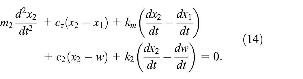
where, k2 and c2 are the damping and stiffness of the vibration isolator, respectively.
The equations describing the oscillatory motion of the valve poppet and body take the following form:

The equation describing the flow rate balance (equation (9)) remains the same.
In the numerical calculations, parameters were adopted in two models of vibration isolators. One vibration isolator is described by the classical Kelvin-Voigt material model with the following parameters: vibration isolator stiffness c2 = 10,000 N/m, and vibration isolator damping k2 = 50 kg/s. The second vibration isolator is described by a non-linear model by the following equation:

Vibration isolator stiffness c2 = 10,000 N/m2, vibration isolator damping k2 = 50 kg/s; other parameter values remain unchanged. Figure 9 presents the ratio of the vibration amplitude of the valve body with and without a vibration isolator for different ground vibration frequencies. It can be assumed that the effect of the properly selecting vibration isolator characteristics is the reduction of valve body vibrations over a wide range of excitation frequencies, that is, the ratio x2i/x2 < 1.

Efficiency of reducing vibrations of the relief valve body at different excitation frequencies.
As shown in Figure 9, the linear vibration isolator is ineffective (x2i/x2 > 1) at the mechanical resonance frequency of the vibrating valve. The higher the ratio of the frequency of external vibrations and the natural frequency of the valve, the greater the effectiveness of vibration isolation. On the other hand, for a vibration isolator with non-linear characteristics, the effectiveness of body vibration isolation is significantly higher. Vibration isolation materials that provide even better vibration isolation efficiency can be investigated.
Discussion
As demonstrated by experimental and simulation studies, pressure pulsations associated with a vibrating hydraulic valve can occur in a hydraulic system. The pressure wave propagates through the hydraulic lines from the source (oscillating valve) to the receiver (hydraulic motor, cylinder, throttle valve). Under certain conditions, hydraulic resonance can occur at a specific length of the hydraulic line. In order to determine the length of the hydraulic line that will result in hydraulic resonance, the hydraulic line (hydraulic long-line) is treated as a binary system element with two inputs and two outputs: pressure p and flow rate q, that is, as a hydraulic quadrupole (Figure 10).

Hydraulic quadrupole: p1, p2– Laplace transforms of pressure at the beginning and end of the line; q1, q2– Laplace transforms of flow rate at the beginning and end of the line; H– operator transition function.
The relationship between the transformations p and q at the beginning (p1, q1) and the end (p2, q2) of the line is expressed by a matrix transition function:

where, L is the length of the line. In the matrix of equation (16) the propagation operator is denoted as:

Wave impedance:

Series impedance:


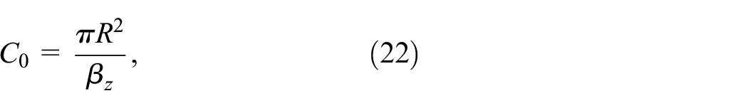
where, R0– resistance of the line (active resistance); M0– inertance (reactive resistance); Y0– admittance of the line; C0– capacitance; s– Laplace transform operator; ρ0– density of the working medium; R– inner radius of the line; β z – equivalent volume elastic modulus of the fluid and the line.
Knowing the load impedance, described by the following relation:

Formulas for the transmittance of a system with a hydraulic long-line can be expressed as follows:


The graphical form of the G p 2,q1 transmittance is shown in Figure 11. In addition, the effect of changing the line material (rigid, flexible) on the occurrence of hydraulic resonance in the line can be analyzed. Two capacity pulsation frequencies were chosen for the analysis: 240 and 15 Hz. This is due the fact that the 240 Hz frequency corresponds to the capacity pulsation frequency of the displacement pump supplying the hydraulic system, while the 15 Hz pulsation frequency corresponds to the valve vibration and pressure pulsation shown in Figure 12.

Transmittance modulus G p 2,q1 of the hydraulic system as a function of hydraulic line length (rigid line) and forcing frequency: (a) rigid line and (b) flexible line.

Transmittance modulus G p 2,q1 as a function of line length L for flexible and rigid lines (solid line – rigid line, dash line – flexible line): (a) forcing frequency f1 = 240 Hz and (b) forcing frequency f1 = 15 Hz.
It can be seen from Figure 12 that for a given capacity pulsation frequency, hydraulic resonance occurs along the length of the line. The higher the forcing frequency, the smaller the resonance length of the line. Furthermore, the material of the hydraulic line affects the occurrence of hydraulic resonance in the line. Switching from rigid lines to flexible lines reduces the resonance length of the line and decreases the amplitude of the transmittance G p 2,q1.
An analytical study of the variation in transmittance values as a function of hydraulic pipe length can be used to determine the resonant length of a hydraulic pipe at a given pressure pulsation frequency. The resonant length of a hydraulic pipe is defined as the length at which the amplitude of the pressure pulsation occurs, for example, at the pipe’s ends. The above considerations are also useful for assessing the effect of changes in hose material on the wave phenomena occurring within it.
Conclusions
The paper identifies the causes of pressure pulsations in the hydraulic system. Particular attention was given to the mechanical vibrations affecting the hydraulic relief valve. As demonstrated by the mathematical model describing the oscillatory motion of the valve poppet, it undergoes vibration when subjected to an external kinematic input. The oscillating valve poppet creates a time-varying flow gap of the valve, altering the fluid’s flow resistance and consequently changing the pressure pulsation spectrum. The proposed mathematical model of the vibrating valve poppet effectively represents the conditions of actual valve operation.
The maximum difference between the results of the numerical solution of the mathematical model and the of experimental tests results is 30%, which can be considered satisfactory result under of dynamic conditions tests. It is expected that if the frequency of external mechanical oscillations is close to the natural frequency of the poppet, then at mechanical resonance, the amplitude of the resulting pressure pulsations will reach its highest values. In the presented experimental results, the amplitude of the pressure pulsations at a mechanical oscillations frequency of 15 Hz reaches the highest value, which is 70% of the amplitude of the pressure pulsations caused by the efficiency pulsations. The occurrence of low-value pulsations of components in the spectrum (below 100 Hz) is particularly unfavorable for the environment in which the hydraulic system operates, including people. This is because pressure pulsations at these frequencies propagate through the fluid and pipes from the source (relief valve) to distant parts of the system.
The modified mathematical model can be used to evaluate the effectiveness of passive vibration isolation methods in reducing valve vibrations. Then, it becomes a two-mass model that takes accounts for the elastic-dissipative properties of vibration isolators. In addition, the length and type of line material affect the amplitudes of pressure pulsations in the hydraulic system.
Future research will address passive pressure pulsation reduction methods using vibration isolators with linear and non-linear characteristics, as well as the supplementary use of passive pressure pulsation dampers that operate on the principle of reflection and interference between the running and reflected pressure waves. The hydraulic long-line considerations presented in this paper also will be applied. The aim of this forthcoming paper is going to be to further reduce pressure pulsations over a wide frequency range.
Footnotes
Appendix
Handling Editor: Sharmili Pandian
Funding
The author(s) received no financial support for the research, authorship, and/or publication of this article.
Declaration of conflicting interests
The author(s) declared no potential conflicts of interest with respect to the research, authorship, and/or publication of this article.