
Abstract
The wear-ring abrasion can cause performance degradation of the marine centrifugal pump. In order to study the effect of front and back wear-ring clearance on a pump, test and numerical simulation were used to investigate the performance change of a pump. The test results show that the head and efficiency of pump decrease by 3.56% and 9.62% respectively at 1.0Qd due to the wear-ring abrasion. Under 1.0Qd, with the increase of the front wear-ring the vibration velocity at pump foot increases from 0.4 mm/s to 1.0 mm/s. The axis passing frequency (APF) at the measuring points increases significantly and there appears new characteristic frequency of 3APF and 4APF. The numerical simulation results show that the front wear-ring abrasion affects the flow at the inlet of the front chamber of the pump and impeller passage. And the back wear-ring abrasion has obvious effect on the flow in the back chamber of the pump and impeller passage, while the multi-malfunction of the front wear-ring abrasion and back wear-ring abrasion has the most obvious effect on the flow velocity and flow stability inside pump. The pressure pulsation at Blade Passing Frequency (BPF) of the three schemes all decrease with the increase of the clearance.
Introduction
Due to the special working environment, such as vibration and corrosion, the marine centrifugal pumps require higher reliability, and performance. As a vital seal part of the centrifugal pump, the wear-ring is applied to limit the leakage of the high-pressure liquid in pump chamber into the low-pressure area at impeller inlet. 1 During the pump operation, the wear-rings can easily be worn off. The wear-ring abrasion not only has effect on the volumetric loss but also on the vibration and internal flow. However, the clearance of the wear-ring is much smaller compared with pump impeller and the flow is more complex. So, it is difficult to carry out experimental research on the wear-ring abrasion. Also, previous simulation and analysis of the internal flow in centrifugal pumps usually neglects the clearance of the wear-ring.2,3
Pan et al. 4 studied the effect of the clearance of front wear-ring on the performance of a centrifugal pump. The research shows that the head and total efficiency increase with the decrease of the clearance. Mou et al. 5 simulated the flow in the centrifugal pump with different structure and clearance of wear-ring, and concluded that the change of wear-ring clearance has a significant effect on the internal flow in the centrifugal pump. Zhao et al. 6 investigated the effect of wear-ring clearances on the radial and axial force of a centrifugal pump. The results showed that the change of the wear-ring clearance has great influence on the axial force of the centrifugal pump. When both the front and back wear-ring clearance change, the effect on the axial force reaches the maximum. Using numerical calculations and experiments, Gao et al. 7 found that the radial force of impeller varies nonlinearly with the change of wear-ring clearance. The influence of the front wear-ring clearance and back wear-ring clearance on the hydraulic performance and the volume loss of the multistage pump are researched by Wu et al. 8 And the results showed that there appears secondary flow under small flow rates. Based on fluid-structure interaction, Gao et al. 9 studied the effect of wear-ring clearance leakage on impeller strength. The existence of clearance makes the fluid between impeller and guide vane produce greater pressure and act on the shroud and hub of impeller. Therefore, it counteracted the part of fluid pressure in the impeller and reduce the deformation and stress concentration of the impeller. Yan et al. 10 studied the effect of flat ring seal and labyrinth seal on performance of a pump-turbine. Under the pump condition, when the clearance reduces by 0.2 mm, the efficiency of flat ring seal model decreases reduced by 5.51% and the efficiency of labyrinth seal model decreases by 5.15%. Yan et al. 11 studied the wall wear law of the centrifugal pump under different wear-rings clearance. With the increase of the clearance, the wear of impeller and volute first increase and then decrease, and the maximum is 0.15 mm and 0.2 mm respectively.
In summary, it can be found that most of the study is done by numerical simulation, and few studies were carried out by experiments. Furthermore, there are few studies on both front wear-ring abrasion and back wear-ring abrasion. In order to study the coupling effect of front ear-ring abrasion and back wear-ring abrasion on the marine centrifugal pump comprehensively, test and numerical simulation were used to investigate the vibration, pressure pulsation and internal flow of a marine pump, which can provide reference for the fault diagnosis of the marine centrifugal pump under malfunction situations.
Research model and scheme
Research model
A vertical single-stage single suction centrifugal pump model is used as the research object. The main design parameters of the pump include flow rate Q0 = 25 m3;/h, head H = 34 m, rotation speed n = 2950 r/min and specific speed ns = 66.7. The impeller inlet diameter D1=65mm, the impeller outlet diameter D2=165mm, the number of impeller blades Z=6.
Research schemes
The research method includes test and numerical calculation. For the sake of simplicity, NPM represents the normal pump model and WPM represents the wear-ring abrasion pump model.
In the test, energy performance and vibration test are conducted for the normal pump and the wear-ring abrasion pump respectively. For WPM, only the clearance of the front wear-ring is changed from 0.15 mm to 0.75 mm. The specific scheme of the test is shown in Table 1.
Test scheme.

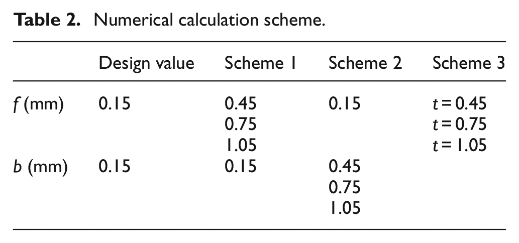
In the numerical calculation, the clearance of the front wear-ring and back wear-ring is represented by f and b respectively, and t means t = f = b. There are three research schemes. Scheme 1 only adjusts the clearance of the front wear-ring, scheme 2 only adjusts the clearance of the back wear-ring and scheme 3 adjusts the clearance of the front wear-ring and back wear-ring simultaneously. The specific scheme of the numerical calculation is shown in Figure 1 and Table 2.

Wear-ring clearance.
Numerical calculation scheme.
Test rig and numerical calculation method
Test system
The test rig is shown in Figure 2. Working fluid flows in from the left pipe and flows out from the right pipe pass through the test pump. The inlet valve 2 and outlet valve 9 are installed on the pipeline, and the flow rate is regulated by the outlet valves. There are six signal inductors on the test rig connected to the computer 1. No. 3 and No. 8 are pressure monitors and No. 4, No. 5, No. 6, No. 7 are vibration monitors. Inlet and outlet pressure transmitters are BP801 liquid level transmitter, whose measuring range is 0–1 MPa and measuring accuracy is 0.5% FS. In the test, INV9822A piezoelectric acceleration sensor is used. Its sensitivity is 10 mV/ms−2 and the available frequency range is 0.5∼8 kHz.

Test rig: 1. Computer, 2. Inlet valve, 3, 4, 5, 6, 7, 8. Signal inductors, 9. Outlet valve.
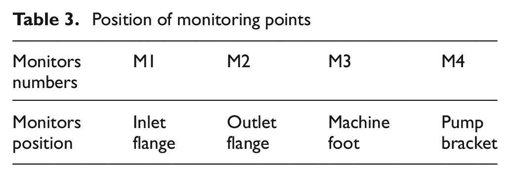
In order to analyse the influence of wear-ring clearance on pump vibration, four monitoring points were placed on the pump. The specific position of vibration monitoring points is shown in Figure 3 and Table 3.

Monitoring points.
Position of monitoring points
Numerical calculation methodology
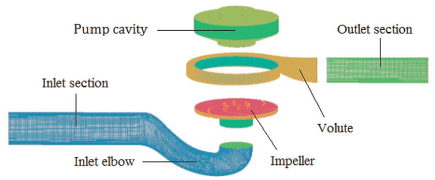
Figure 4 shows the simulation domain of the centrifugal pump, which consists of the inlet section, inlet elbow, impeller, volute, pump chamber, and the outlet section. Therefore, the energy losses in all components of the pump have been considered. The length of the inlet and outlet pipe is set as four times of the pipe diameter to ensure the simulation accuracy.
Whole grid structure.
The ANSYS-ICEM is used for all the grid generation in this paper. Computational domains are generated by hexahedral cells to improve simulation precision. The grid diagram is shown in Figure 4.
The RNG k-ε turbulence model is used to simulate the internal flow of the pump. 12 The equation is as follows:

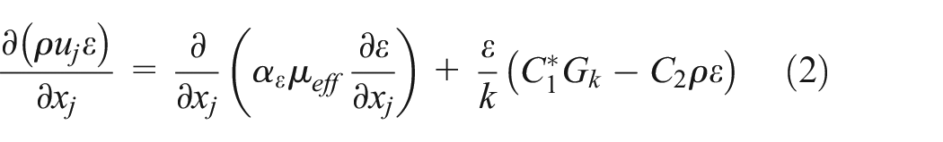
Where μeff = μ + μt; Cμ = 0.0845; αk = 1.39; αε = 1.39; C1 = 1.42; C2 = 1.68.

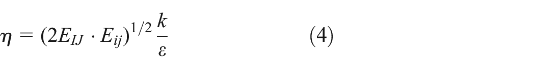
Where η0 = 4.377; β = 0.012.
In order to examine the grid independency, five different grids are considered. The simulation results are shown in Table 4. It can be seen that the head of scheme 3 and scheme 4 are the same. Therefore, considering the calculation resources and time, the scheme 3 is selected finally.
Grid dependency check.

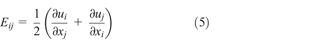
The unsteady flow simulation is an extension of a steady state numerical simulation. For the unsteady simulation, the time-step is set to be 1.13 × 10⁻⁵ s (the impeller rotates 2°). The total time-steps are 1080. The last cycle of the impeller rotation is selected for analysis. The numerical setup is summarized in Table 5. The whole research flow chart of this paper is shown in Figure 5.
Summary of the numerical setup.
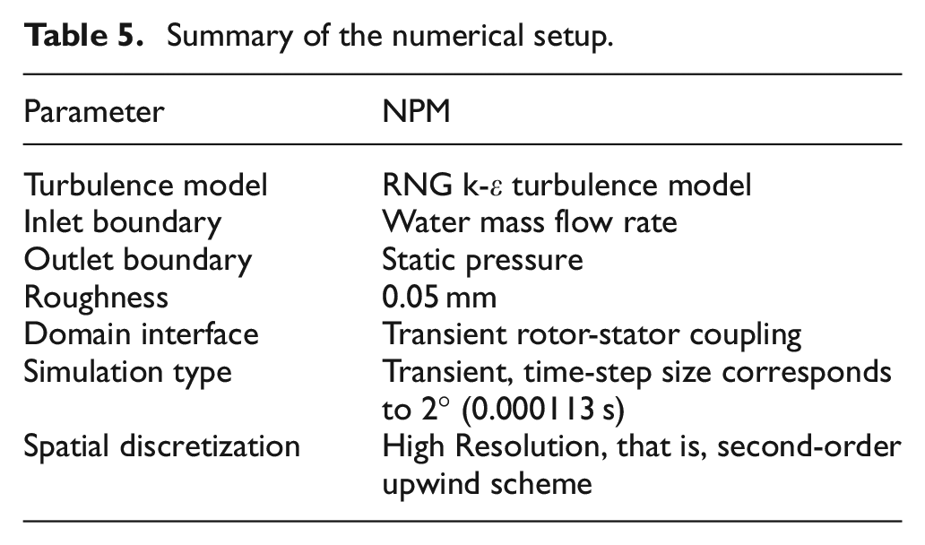
Research flowchart.
Figure 6 displays the energy performance comparison between the numerical simulation and test under 0.2Q0, 0.4Q0, 0.6Q0, 0.8Q0, 1.0Q0, 1.2Q0, and 1.4Q0. The variation trend of the numerical head and efficiency curve is consistent with the test results. Although test curves of the head and efficiency curve are lower than numerical simulation curve, the deviation of head and efficiency is less than 5% under various flow rates. The reason for this phenomenon is that the friction between the bearing and seal ring is not considered in the numerical simulation. Therefore, the numerical simulation is accurate and the calculation results are credible.

Energy performance.
Test results and analysis
Comparison of energy performance
Figure 7 shows the comparison of energy performance between NPM and WPM under seven flow conditions. It can be found that the wear-ring abrasion has a great influence on the pump head, which results in 3.56% reduction of head at 1.0Q0 and 5.44% at 1.4Q0. It is obvious that the wear-ring abrasion affects more on the pump efficiency and the effect increases with the increase of flow rate, which results in 9.62% decrease of efficiency at 1.0Q0, 10.55% at 1.4Q0. This is because with the increase of the clearance of the orifice ring, more high-pressure fluid leaks out from wear ring clearance, the turbulent intensity increases, and the energy dissipation of the fluid increases, which ultimately leads to the increase of the hydraulic loss in the impeller and the decrease of the hydraulic efficiency.

Energy performance of the NPM and WPM.
Vibration amplitude analysis
Amplitude analysis is part of the time domain characteristic analysis of signals. The average amplitude is the mean of the signal amplitude over a period of time, and its expression is as follows: 13

Where x(t) is the instantaneous amplitude of vibration; T is the total time.
Figure 8 is the vibration velocity amplitude of NPM and the WPM. Compared with NPM, the vibration at the monitoring points of WPM all increase in varying degrees. For NPM, the vibration amplitude under 0.2Q0∼0.6Q0 is much higher than that under 1.0Q0∼1.4Q0. When the pump runs under small flow rates, the fluid leakage from the wear-ring clearance makes the flow of the pump more disorderly, which causes the increase of vibration amplitude. When the pump runs at large flow rate, the effect liquid leakage will get weaker due to the large velocity at the pump inlet.

Vibration velocity amplitude: (a) NPM and (b) WPM.
Under the design flow rate, the wear-ring abrasion has the greatest influence on the vibration of the model pump foot, and the vibration velocity at pump foot increases from 0.4 mm/s to 1.0 mm/s. When the pump runs under small flow rates, the wear-ring abrasion will aggravate the vibration of the pump bracket and the virbation gradually decreases with the increase of the flow rate.
Frequency domain analysis of vibration
Figure 9 shows the vibration velocity in the frequency domain. As can be seen from Figure 9, except for M4, the vibration amplitudes at APF and BPF of M1, M2, and M3 change little. For WPM, the vibration amplitudes at APF of M4 is higher than that of NPM, while the vibration amplitudes at BPF of M4 is lower. This is due to unstable flow at the pump inlet caused by the wear-ring abrasion, which results in the vibration increase at APF and vibration decrease at BPF.
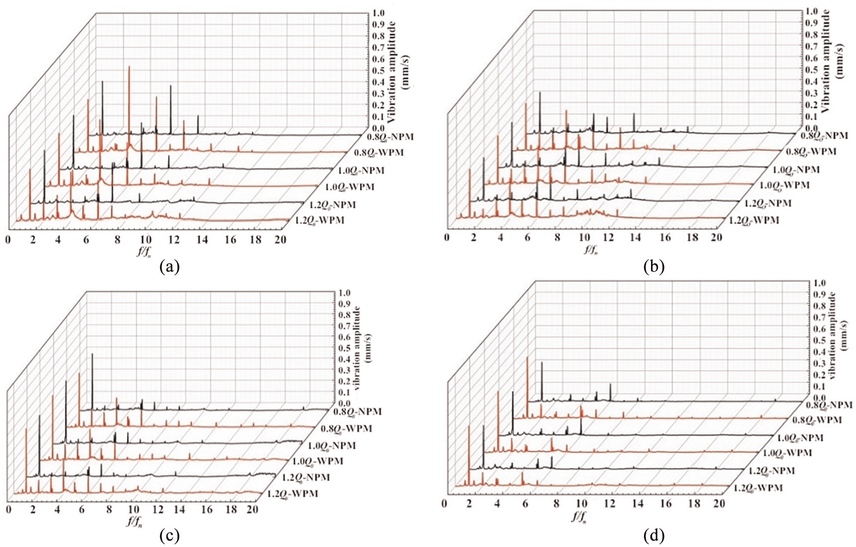
Vibration in frequency domain: (a) vibration monitoring point M1, (b) vibration monitoring point M2, (c) vibration monitoring point M3, and (d) vibration monitoring point M4.
For NPM, except the APF and BPF, the vibration amplitudes at other frequency are not obvious and low. For WPM, new characteristic frequencies of 3APF and 4APF appear. Under 1.0Q0, the vibration amplitudes of M1, M2, M3, and M4 at 3APF are 0.19 mm/s, 0.11 mm/s, 0.15 mm/s, and 0.06 mm/s respectively. The vibration amplitudes of M1, M2, M3, and M4 at 4APF are 0.59 mm/s, 0.34 mm/s, 0.28 mm/s, and 0.04 mm/s.
To sum up, the wear-ring abrasion has little effect on the vibration at APF and BPF, but can make the vibration amplitude at the APF harmonic frequency increase significantly.
Total vibration level analysis
The magnitude of the vibration is often expressed in decibels (dB). The calculation formulas are as follows: 14

Where A is the effective value of vibration acceleration measured in m/ss and A0 is the reference value, 10−6 m/ss.
Figure 10 is the total vibration amplitude comparison between the NPM and the WPM under 0.8Q0, 1.0Q0, and 1.2Q0. At M1 and M2, the total vibration amplitude difference between NPM and WPM changes less and less with the increase of flow rate. The total vibration amplitude difference at the M1 increases by 3.82 dB, 1.41 dB, and 0.96 dB respectively under 0.8Q0, 1.0Q0, and 1.2Q0. The total vibration amplitude difference at the M2 increases by 4.5 dB, 2.41 dB, and 1.96 dB respectively under 0.8Q0, 1.0Q0, and 1.2Q0. This is maybe the wear-ring abrasion aggravates the back-flow at the pump inlet and outlet, and lead to a larger fluid exciting forces. With the increase of the flow rate, the flow will be more chaos accordingly. At M3, the vibration amplitude difference of NPM and WPM are almost the same. Under 1.2Q0, the total vibration amplitude at the M4 increases the most (2.56 dB).

Total vibration amplitude: (a) 0.8 Q0, (b) 1.0 Q0, and (c) 1.2 Q0.
It can be concluded that the wear-ring may be worn when the vibration at the pump inlet and outlet increased obviously under the small flow rate, or the vibration at the pump bracket increased under the larger flow rate.
Numerical calculation results and analysis
Flow characteristics
Figure 11 shows the relative velocity distribution and streamline inside the impeller channel. For NPM, the velocity distribution inside the impeller is uniform, and the distribution of low-velocity region is the same near each blade pressure side. As the f increase, the low velocity region near the blade pressure side get smaller and the streamline distribution is uniform and stable. The low velocity region near the blade pressure side get larger and the flow at impeller inlet becomes more chaotic with the increase of b. Meanwhile, the streamline distribution becomes disordered, and a flow vortex appears at the impeller inlet. When t increases, the low velocity region begins to break away from the blade surface and gradually begins to diffuse to the middle of the channel. And the streamlines are more disorganized.
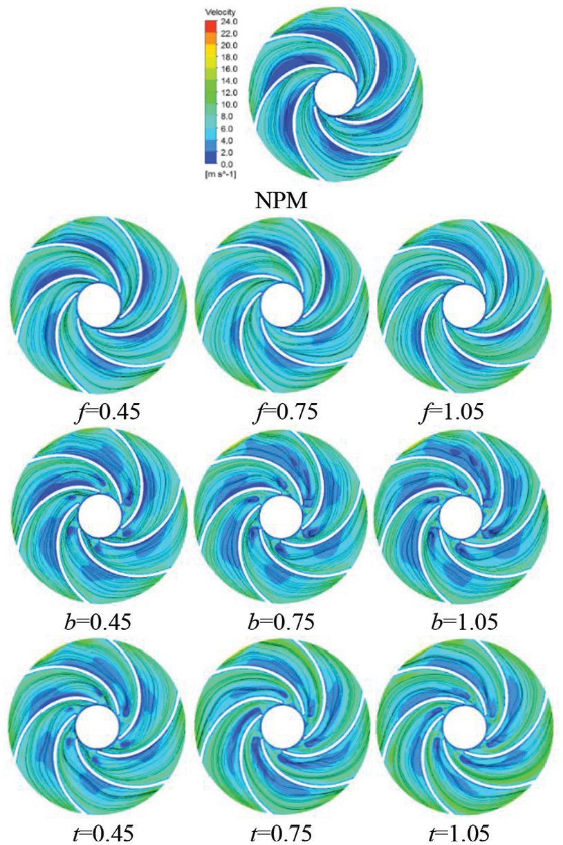
Relative velocity and streamline (1.0 Q0).
It is obvious that the influence of the back wear-ring abrasion on the flow in the impeller is greater than that of the front wear-ring abrasion. This is because the high-pressure fluid at the impeller outlet will flow through the clearance of the wear-ring, and then through the balance hole into the impeller passage directly, resulting in unstable flow inside the impeller.
Figure 12 is the static pressure distribution in the axial plane of pump. With the increase of f, the pressure in the front pump chamber decreases, and the pressure in the impeller and the back pump chamber increases. This may be because with the increase of the front wear-ring clearance, the liquid leakage of the front wear-ring increases, which leads to the increase of vortex loss in the front pump chamber. Meanwhile, the liquid delivered by the pump decreases, so pressure in the pump increases.

Static pressure distribution (1.0 Q0).
With the increase of b, the pressure in back pump chamber increases and the low-pressure area of impeller become larger. This may be due to more fluid enters the back pump chamber with the increase of back wear-ring clearance. However, the diameter of the balance hole remains unchanged, so more fluid produces the squeezing effect in the back pump chamber, resulting in the increase of the pressure in the back pump chamber. Also, as the back wear-ring clearance increases, the velocity at the impeller balance hole get larger, which makes the pressure in the impeller decrease. Correspondingly, the pressure in the front pump chamber also decreases.
It can be seen from Figure 12 that the change of the pressure in the pump chamber is more obviously with the change of t than that with the change of f and b due to the multi-malfunction.
Pressure pulsation analysis
As shown in Figure 13, the pressure pulsation is monitored at P0, which is near the front wear-ring.

Monitoring point of pressure pulsation.
The pressure pulsation data were dealt with dimensionless method by pressure 15
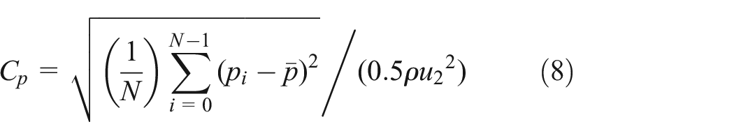
where pi is the transient static pressure;
Figures 14 to 16 show the pressure pulsation of scheme 1, 2, and 3 in time domain and frequency domain respectively. It is observed that the pressure pulsation of WPM in time domain of the three schemes is all bigger than that of the NPM. Figures 14(a) to 16(a) show that the pressure pulsation under different front wear-ring clearance changes periodically in time domain. There are six peaks in one cycle of impeller rotation, which is determined by the blade number. The main effect of f is to reduce the peak-to-peak value, while b reduces the wave trough value. When f is 0.15 mm, 0.45 mm, 0.75 mm, and 1.05 mm, the corresponding peak-to-peak value is 0.014, 0.011, 0.012, and 0.009 respectively. When b is 0.15 mm, 0.45 mm, 0.75 mm, and 1.05 mm, the corresponding wave trough value is −0.006, −0.010, −0.013, and −0.011 respectively. With the increase of the clearance, the waveform becomes more and more complex, which is due to the structure of the centrifugal pump gets more asymmetrical. This aggravates the rotor-stator interaction and makes the pressure pulsation larger.

Pressure pulsation of P0 in scheme 1: (a) time domain and (b) frequency domain.

Pressure pulsation of P0 in scheme 2: (a) time domain and (b) frequency domain.
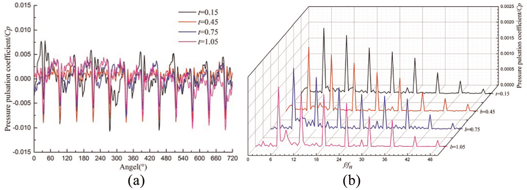
Pressure pulsation of P0 in scheme 3: (a) time domain and (b) frequency domain.
According to Figures 14(b) to 16(b), it can be seen that the pressure pulsation frequencies are mainly concentrated in the low-frequency region, while the amplitude of the pressure pulsation in the high-frequency region is relatively weak. In each scheme, the main frequency is the BPF and its harmonic frequency. When t is 0.15 mm, 0.45 mm, 0.75 mm, and 1.05 mm, the corresponding Cp value at BPF is 0.021, 0.019, 0.015, and 0.012 respectively. When f is 0.45 mm, 0.75 mm, and 1.05 mm, the corresponding Cp value at BPF is 0.018, 0.016, and 0.014 respectively. When b is 0.45 mm, 0.75 mm, and 1.05 mm, the corresponding Cp value at BPF is 0.020, 0.019, and 0.018 respectively. The pressure pulsation at BPF decreases with the increase of the wear-ring clearance.
Therefore, the wear-ring abrasion has great influence on pressure pulsation at the BPF and its harmonic frequency, but has negligible effect on the APF and its harmonic frequency. Usually, the main frequency of the pressure pulsation at the wear-ring clearance is the BPF. When the wear-ring clearance value decreases, the pressure pulsation in the pump will increase at different degrees. To sum up, the t has the greatest effects on the decrease of pressure pulsation at BPF while the b has little effect on it.
Conclusion
This paper involves the test and numerical simulation results of a centrifugal pump with the malfunction of wear-ring abrasion. Experimental test of the normal pump model and the front wear-ring abrasion pump model was performed. And three kinds of abrasion schemes were considered to demonstrate the malfunction of front wear-ring abrasion and back wear-ring abrasion. The energy performance, vibration, internal flow, and pressure pulsation were studied.
The energy performance test shows that the front wear-ring abrasion has a great effect on the pump head and efficiency. Under the design flow rate, the head decreases by 3.56% and the efficiency decreases by 9.62%.
The vibration test shows wear-ring abrasion has minor impact on the APF and BPF, but it will increase the harmonic frequency of APF. And there appears new characteristics frequency of 3APF and 4APF in the frequency domain.
The inner flow simulation presents when the front wear-ring clearance increases, the low velocity zone near the blade pressure side gets smaller. When the back wear-ring clearance increases, the low velocity zone near the blade pressure side gets larger. With the increase of the front wear-ring clearance, the pressure in the front pump chamber decreases, the pressure in the impeller and the back pump chamber increases. With the increase of the back wear-ring clearance, the pressure in the back pump chamber increases and the low-pressure area of impeller becomes larger.
The pressure pulsation simulation presents when the front wear-ring clearance increases, the peak-to-peak value decreases. When the back wear-ring clearance increases, the wave trough value decreases. And the pressure pulsation frequencies are mainly concentrated in the low-frequency region. The pressure pulsation at BPF decreases with the increase of the wear-ring clearance.
Footnotes
Appendix
Handling Editor: James Baldwin
Declaration of conflicting interests
The author(s) declared no potential conflicts of interest with respect to the research, authorship, and/or publication of this article.
Funding
The author(s) disclosed receipt of the following financial support for the research, authorship, and/or publication of this article: This study was supported by the National Natural Science Foundation of China (No. 51779108, 51979124) and Priority Academic Program Development of Jiangsu Higher Education Institutions (PAPD).