
Abstract
In this paper, attention was focused on identifying the components of the amplitude-frequency spectrum of pressure pulsations in a hydraulic system in which an external low-frequency mechanical vibration was subjected to a proportional hydraulic directional control valve. It was observed that an operating machine or device equipped with hydraulic valves is a source of mechanical vibrations with a wide frequency spectrum. The influence of these vibrations on the pressure pulsation spectrum was analyzed, identifying the components resulting from the forcing of the directional control valve spool. In addition, it was noted that the pressure pulsation spectrum includes components resulting from the pulsation of the displacement pump output feeding the hydraulic system. A description of these spectrum components was also made and, using the solution superposition method, the components of the pressure pulsation spectrum over a wide frequency range were identified.
1. Introduction
In a real hydraulic system, the flow rate from a displacement pump oscillates around a fixed value and can be described by a polyharmony function with a form depending on the pump's design (Zhai et al., 2023). The varying flow rate reaching the control element of the hydraulic component causes a change in the hydrodynamic force acting on the control element of the hydraulic valve. Performance pulsation is the main, though not the only, source of pressure pulsation in a working hydraulic system (Xu et al., 2023).
In addition, in real conditions, there are also vibrations resulting from the movement of a mobile machine containing a hydraulic system on uneven ground or vibrations from rotating elements such as the engine drive shaft (Skliros, 2019), which are transmitted to the construction of the mobile machine and through it to each element (Figure 1(a)). If the generator of these vibrations is a rotating element, then its describing function can be set out into a Fourier series. These vibrations, transferred to the control element of the hydraulic valve, become a kinematic force applied to the valve body and, depending on the design, are transferred to the control element. General views for introduction part: (a) example of mobile machine; (b) course of performance pulsation of the gear pump.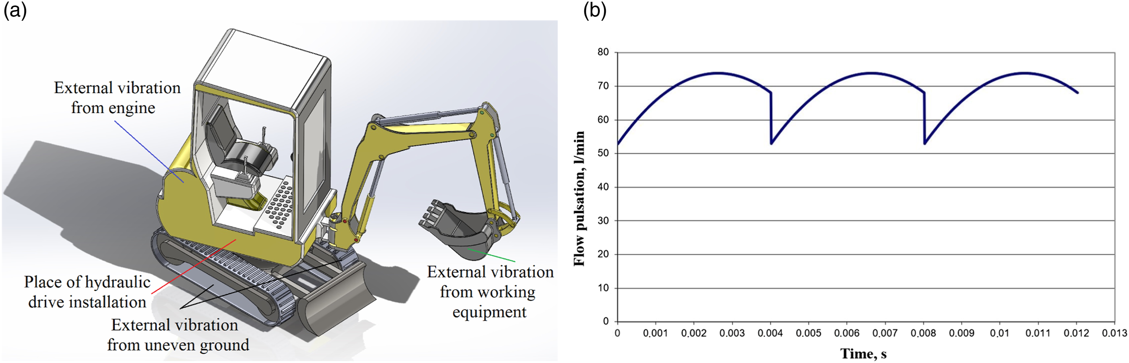
In the process of designing a hydrostatic drive, it is necessary to be aware of the significant impact of the operating conditions, in the form of forcing coming from the pulsations of the pump output and vibrations taken from the device frame, on the operation of the hydraulic component installed on this frame, and therefore on the entire hydrostatic drive (Figure 2). The new requirement for hydraulic elements operating in real conditions should focus on the condition of the invariance of this element's operation from external forcing or indication of the frequency of external mechanical vibrations at which an increase in the amplitude of pressure pulsations is observed. As can be seen from Figure 2, the vibration acceleration spectrum of real objects contains components with lower frequencies (20–200 Hz), which, on the other hand, can excite the hydraulic control element of the valve. Figure 1(b) presents a graphical representation of the theoretical instantaneous efficiency, this kind of efficiency well investigated in research works by Choudhuri et al. (2022) and Cieślicki and Karpenko (2022). Time course and amplitude-frequency spectrum (rotational speed of the pump shaft n = 1450 rpm): (a) recorded vibration acceleration of tank plate of the hydraulic power pack; (b) The amplitude-frequency spectrum of the vibration acceleration of the tank plate of the hydraulic power pack.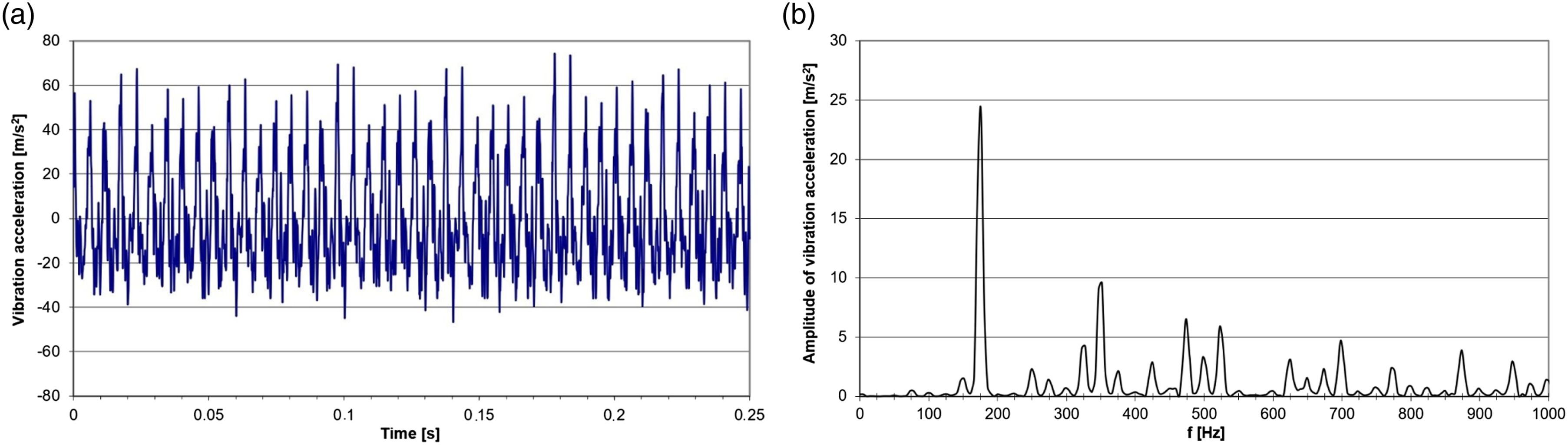
The devices in which hydraulic elements are commonly found are hydraulic power packs. During its operation, the hydraulic power unit is a generator of mechanical vibrations. An example of the time course and amplitude-frequency spectrum of vibration acceleration of the hydraulic power pack of the tank plate is shown in Figure 2.
In the literature, there is a certain variety of models describing the basic hydraulic elements, such as lift valves or directional valves operating in the conventional or proportional technique. The authors of papers, Valdés et al. (2014) and Guo (2022), describing the transient state of the lift valve operation take into account the forces acting on the control element: inertial force, viscous friction force, dry friction force, hydrostatic force, hydrodynamic reaction, and stiffness of the springs.
In the literature, one can distinguish directions that undertake theoretical considerations and experimental research. One of the directions of interest of scientists is the assessment of dynamic properties under step or harmonic forcing (Liu et al., 2014; Wu et al., 2021). For phenomena occurring in transient states, researches (Bouzidi et al., 2018, 2019) use the natural vibrations of the control element (mushroom, slider, etc.).
The second direction of valve testing is the analysis of stable operation ranges (Kumar et al., 2021; Tripathi et al., 2021; Liu et al., 2022). In the paper Liu et al. (2022), the authors emphasize that the hydrodynamic force in a lift valve has a large impact on the static and dynamic characteristics of this type of valve. On the basis of the momentum law, the computational formula for the flow force of the poppet valve was modified, and a new structure of the valve poppet-seat structural joint was designed. The impact of the compensation of the improved structure of the poppet-seat structural joint on the hydraulic force is discussed.
On the other hand, Han et al. (2017) and Zhao et al. (2022) indicate that the cause of vibration of the mushroom of the lift valve may be the occurrence of cavitation. The authors mentioned above treat the valve as an element located on rigid structures that is not subject to vibrations. In the group of commonly described extortions in lift and slide valves, it is assumed that there are no mechanical vibrations coming from the steel frame on which the valve body is mounted. Thus, no external forces are transferred to the valve control in previous models that describe the operating state of the valve.
In the works, Lisowski et al. (2013) and Zhang et al. (2019) can find a simplified mathematical description of the directional spool valve, which was described by the differential equation of the second-order inertial term. Also, in these works, they do not mention external extortions, in the form of efficiency pulsations from the pump and mechanical vibrations, on the behavior of the control element—the spool of the directional valve. As a result, the solution of such an equation does not include the influence of the aforementioned forcing on the pressure pulsation spectrum of the hydraulic system in which the valve operates.
The problems of the impact of disturbances coming from the ground, as well as the design and pulsation of the displacement pump capacity on changes in the amplitude-frequency spectrum of pressure have so far been insufficiently developed. Pressure pulsation in a hydraulic system is usually a negative phenomenon and should therefore be limited. In order to effectively reduce pressure pulsation in a hydraulic system, it is important to understand the causes. One of the main causes of pressure pulsation is displacement pump performance pulsation. In addition to this cause, there are others. The paper presents experimental and theoretical considerations on the possible influence of external mechanical vibrations on changes in the amplitude-frequency spectrum of pressure pulsation in a hydraulic system. The paper assumes that the directional control valve is affected by mechanical vibrations, which may originate, for example, from the machine frame on which this valve is installed.
2. Mathematical model of proportional directional spool valve taking into account external mechanical vibrations
Solving the dynamics of a hydrostatic drive system or a hydraulic component is very difficult if all factors related to its operation are taken into account, with direct changes in the working conditions of one element of the hydraulic system, for example, a directional valve, with a sudden change in pump capacity, the pressure and flow rate of the medium change suddenly.
When building the mathematical model, the following detailed simplifying assumptions were made in the mathematical model of the directional valve: • Impact of pressure pulsation caused by capacity pulsation is neglected; • Influence of the elasticity of the directional valve body and slider was omitted, and a completely rigid mounting of the directional valve to a rigid base surface was assumed; • Clustered parameters are assumed because a system with distributed parameters must be described by partial differential equations, which are generally very difficult to solve; • Hydraulic conduits are characterized by active resistance, inertance, and capacitance concentrated at the points of the considered system; • Flow losses in hydraulic lines have been omitted; • Working medium does not change its physical properties; • No cavitation of the working medium. • Displacement pump is driven by an electric motor at a constant speed.
2.1. Analysis of loads acting on the spool of the directional valve
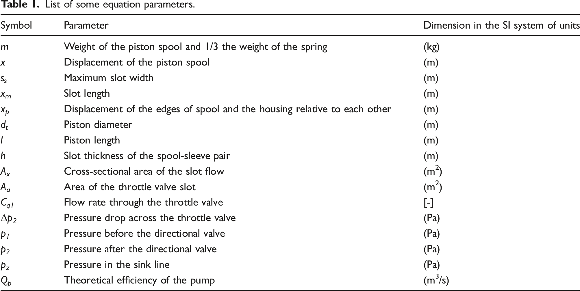
When starting the analysis of the theoretical model of the proportional directional valve, the starting point is the balance of forces acting on the spool. There is a division of forces due to the direction of action into transverse and longitudinal. These forces determine the resistance of the spool movement that must be overcome during override. Lateral forces of the movement of the spool relative to the sleeve do not have a direct effect, but acting perpendicularly to the axis of the spool, they determine the friction forces occurring on the surface of the spool. On the other hand, the values of longitudinal loads are often much greater than the values of the inertia and friction forces, therefore, they decisively determine the force necessary to override the spool of the directional valve, Figure 3. Forces (projection of forces) acting on the spool of the directional valve equipped with proportional electromagnets: Fb- spool inertia force, Ft- friction force in the slide pair, Fd- hydrodynamic force, Fs- force of springs centering the spool, FM- proportional solenoid force.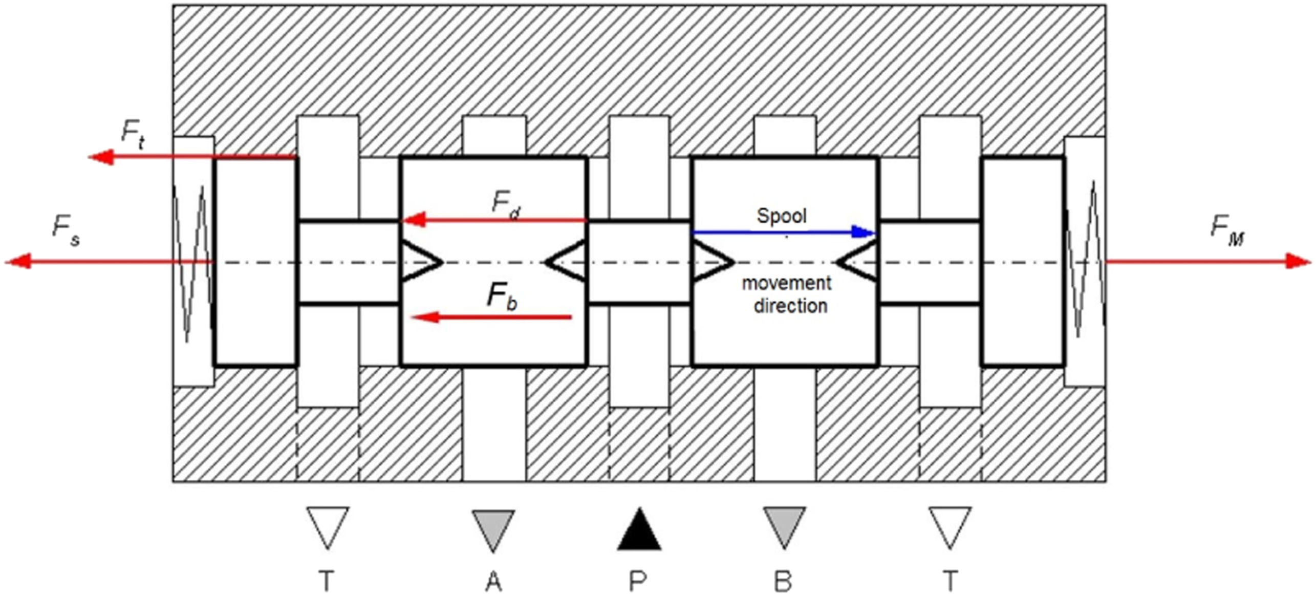
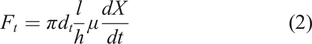
Due to the fact that the channels closed by the spool pistons are made around the entire circumference of the sleeve, the distribution of pressure acting on the piston is even over its entire circumference, which means that the spool is only loaded with radial forces. The necessary axial force needed to override the spool is the sum of the inertia forces of the spool and the liquid mass associated with it, friction in the sleeve and forces resulting from the flow of the medium in the directional valve channels at a certain speed. The inertia force can be determined from the relationship
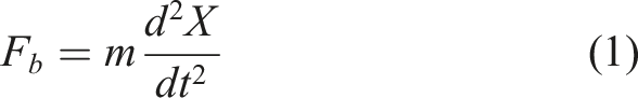
For a directional valve with centering springs, an additional third of their weight is taken into account. At high overshoot speeds, which may occur due to external kinematic forcing, Newtonian friction should be taken into account in the form of the relationship (Hidalgo and Garcia, 2017)
The hydrostatic forces caused by the flow of liquid through the channels and slots of the spool pair are the result of the pressure difference of the input and output streams in the channel caused by the flow resistance through the control slot (Li et al., 2023). In general, these differences are not large, but when acting on larger surfaces, they can cause significant forces. However, due to the fact that the faces of the pistons are equal, these forces compensate each other.
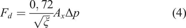
Much greater are the forces caused by the stream momentum change—hydrodynamic forces. These forces act on both the elements of the spool pair and the liquid. The hydrodynamic force always acts in the opposite direction to the direction of the spool movement, opposing its displacement. The relationship determining the hydrodynamic force in the directional valve can be written as follows

The angle of the jet outflow from the control slot formed by the sharp-edged piston in the spool sleeve channel depends on the relative opening of the flow channel x. So, the angle
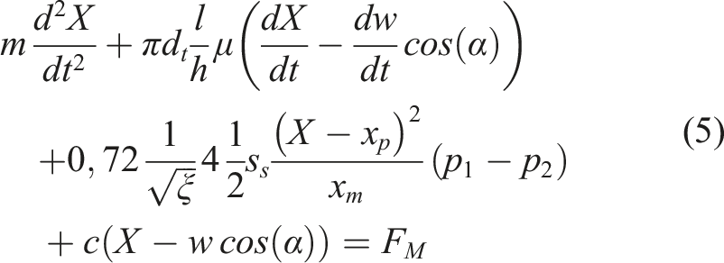
External mechanical vibrations acting on the tested hydraulic element (in this case, the proportional valve) can be described by a harmonic function of the form: w(t) = w 0 sin (2πft). Thus, the control element (distributor spool) is excited by vibrations of frequency fi and amplitude w 0 .
The equation of forces acting on the spool valve in a quasi-steady state, that is, in the state of external kinematic inputs, they should take into account that deformations and elastic forces are proportional to the relative displacement y = x - w, and Newtonian (liquid) friction forces—to the relative speed. Bearing this in mind and recording the angle between the direction of extortion and the direction of movement of the spool as α the equation describing the oscillating movement of the spool during the flow of liquid through the distributor is written in the modified form
The second equation of the mathematical model is the flow balance equation for the hydraulic system of the considered proportional directional valve. In this equation, the first term corresponds to the capacity of the displacement pump, the second term describes the flow through the directional valve port, the third term represents the flow due to leaks in the pump, and the fourth term represents the flow due to the compressibility of the hydraulic oil and hoses due to pressure. For the hydraulic system of the tested proportional directional valve, a third equation can be written, which is an equation describing the flow balance, taking into account the adjustable throttle valve. Finally, the system of equations forming the mathematical model of the considered proportional valve, taking into account external mechanical vibrations and the angle between their direction and the main axis of the valve spool, is as follows
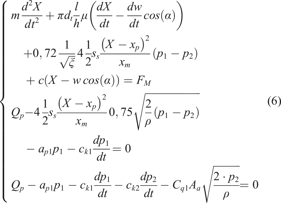
As a result of solving the system of equation (6) and substituting the numerical values of the parameters, functions satisfying the equations of the form X = f(t), p 1 = f(t) and p 2 = f(t) are obtained, describing, respectively, the position of the spool and the pressure pulsation resulting from vibrations of the spool caused by external mechanical vibrations before and after the forced proportional directional valve, respectively (at the measurement point p 2 , will be displayed further).
2.2. Numerical solution of the mathematical model
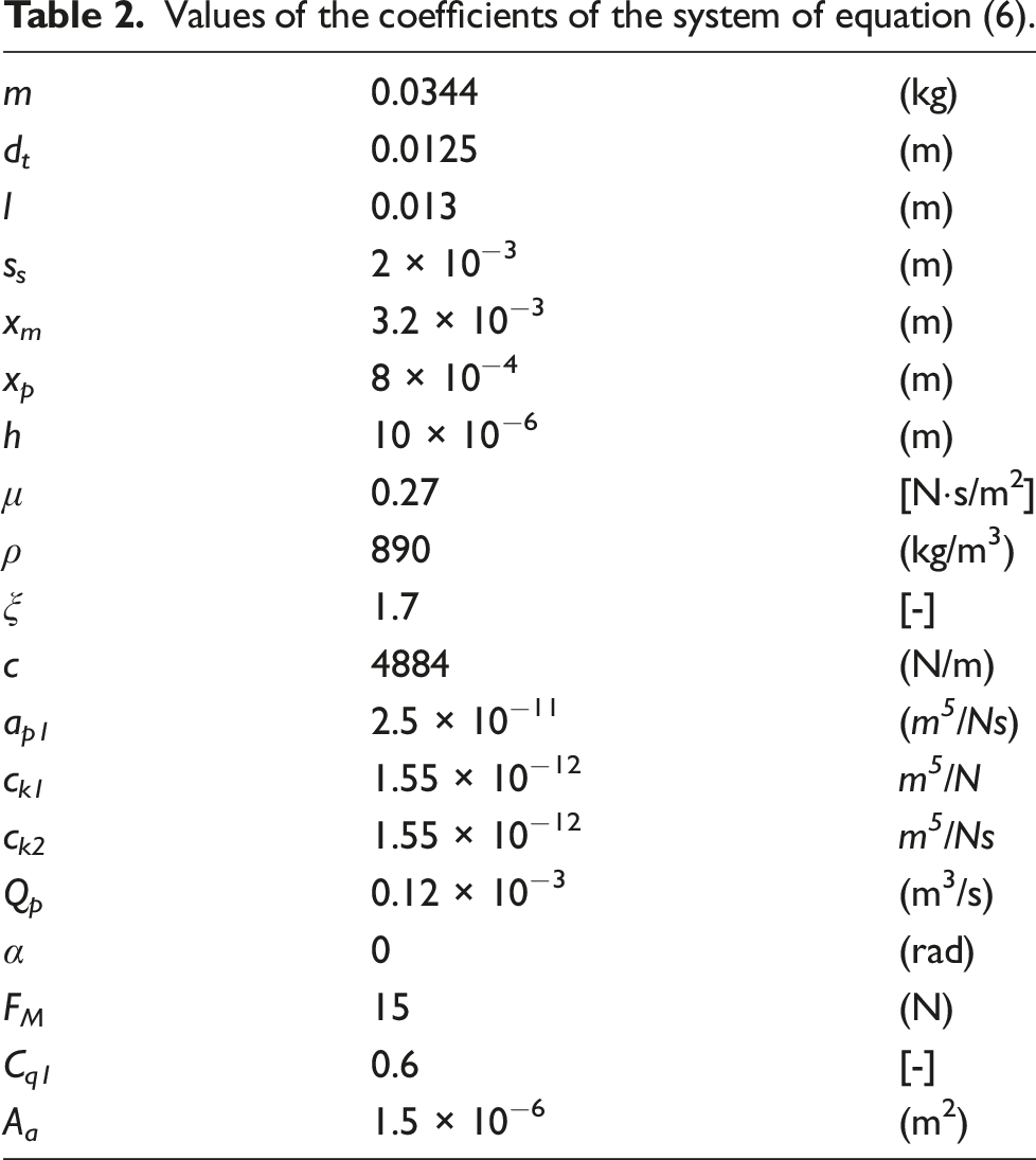
Values of the coefficients of the system of equation (6).
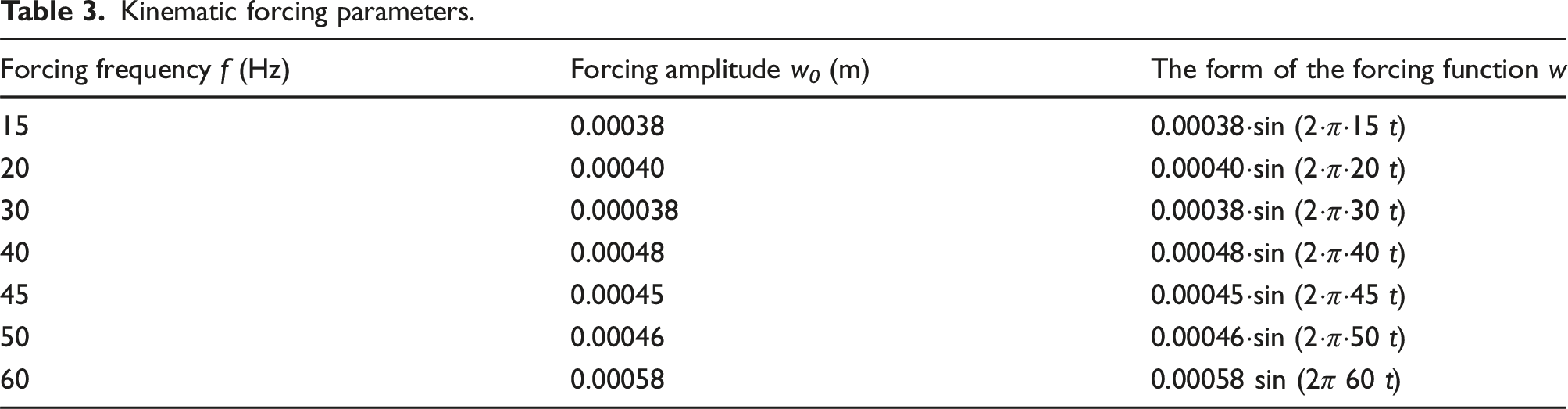
The kinematic forcing acted directly on the body of the proportional directional control valve. Figure 4 The proportional directional control valve was mounted non-susceptible to the vibrating hydraulic simulator table. The hydraulic simulator table was the source of the kinematic forcing. The direction of the kinematic forcing coincided with the main axis of the spool (spool movement axis). Parameters of external harmonics of mechanical vibrations acting on the directional valve (kinematic forcing) were also assumed, Table 3. Comparison of the amplitude-frequency spectrum of pressure pulsations p
2
for different frequencies of the external forcing. Kinematic forcing parameters.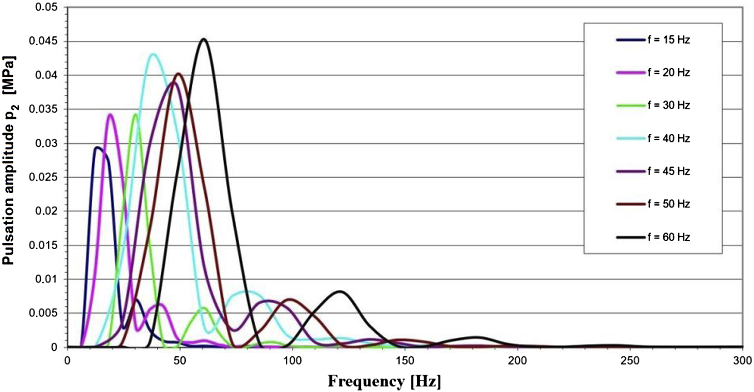
Comparisons of the amplitude-frequency spectrum for different external forcing frequencies (according to Table 3) were made in Figure 4.
From the results shown in Figure 4, it can be seen that for the proportional directional valve tested, components with frequencies corresponding to the frequencies of external mechanical vibrations appear in the pressure pulsation spectrum. Figure 4 also shows that the amplitude of pressure pulsations p
2
caused by external vibrations with a frequency of 60 Hz is the largest. This frequency is close to the undamped natural frequency f
0
of the spool of the considered directional valve because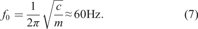
As the difference between the natural frequency of the undamped spool and the frequency of the external kinematic forcing increases, the amplitude of the harmonic component of the pressure pulsation decreases.
The presented mathematical model can be used to assess the impact of changes in selected design or operating parameters on changes in the pressure pulsation spectrum with a vibrating directional valve. In numerical considerations, it was decided to change the capacitance value. The capacitance of the hydraulic system can be changed, for example, by changing the volume of the liquid enclosed by the conduits or by changing the conduit material, for example, by replacing flexible conduits with steel conduits. The results of numerical solutions of the model (equation (6)) for equal capacitance values in the form of the amplitude-frequency spectrum of pressure pulsations are shown in Figures 5, 6, and 7 for the external frequency of mechanical vibrations acting on the directional valve equal to 60, 30, and 15 Hz. The influence of the hydraulic system capacitance on the value of the pressure pulsation amplitude for the kinematic forcing frequency f = 60 Hz. The influence of the hydraulic system capacitance on the value of the pressure pulsation amplitude for the kinematic forcing frequency f = 30 Hz. The influence of the hydraulic system capacitance on the value of the pressure pulsation amplitude for the kinematic forcing frequency f = 15 Hz.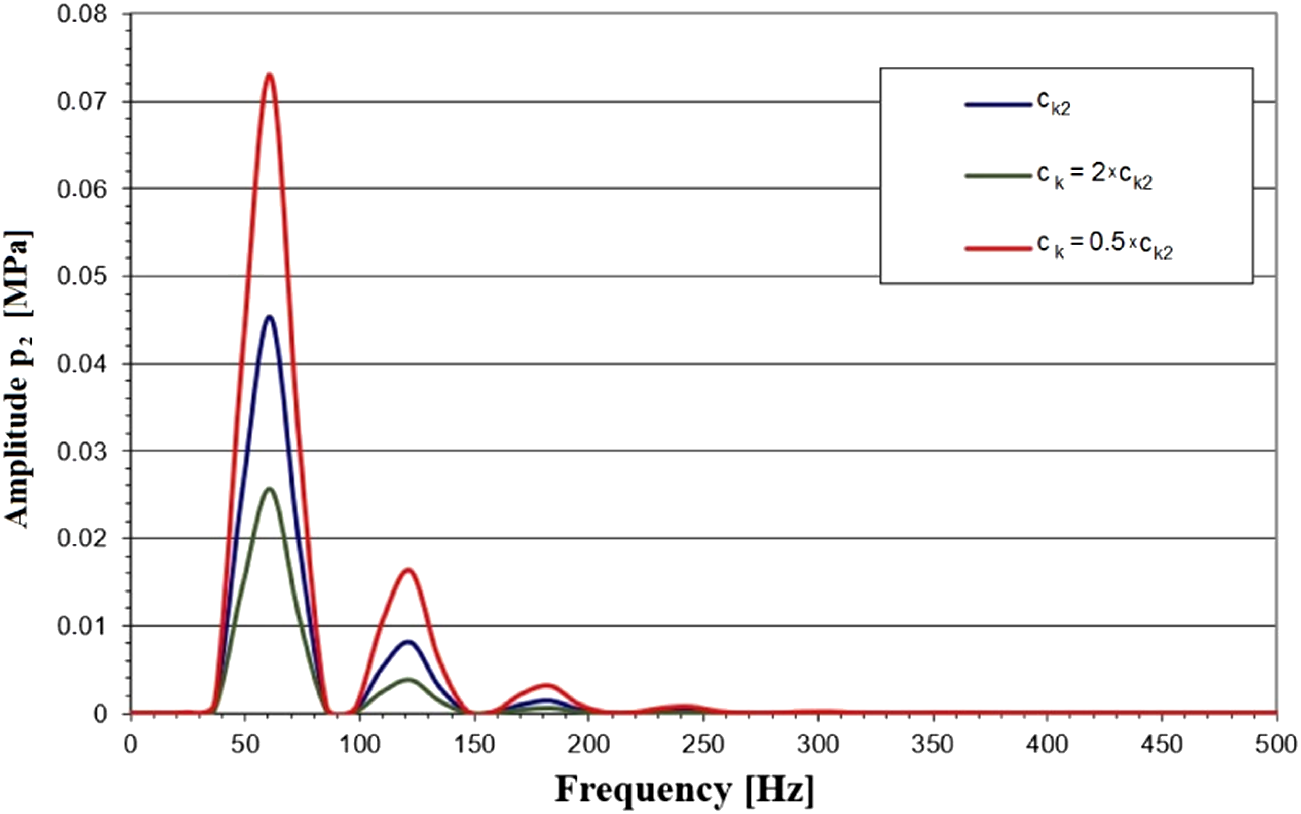
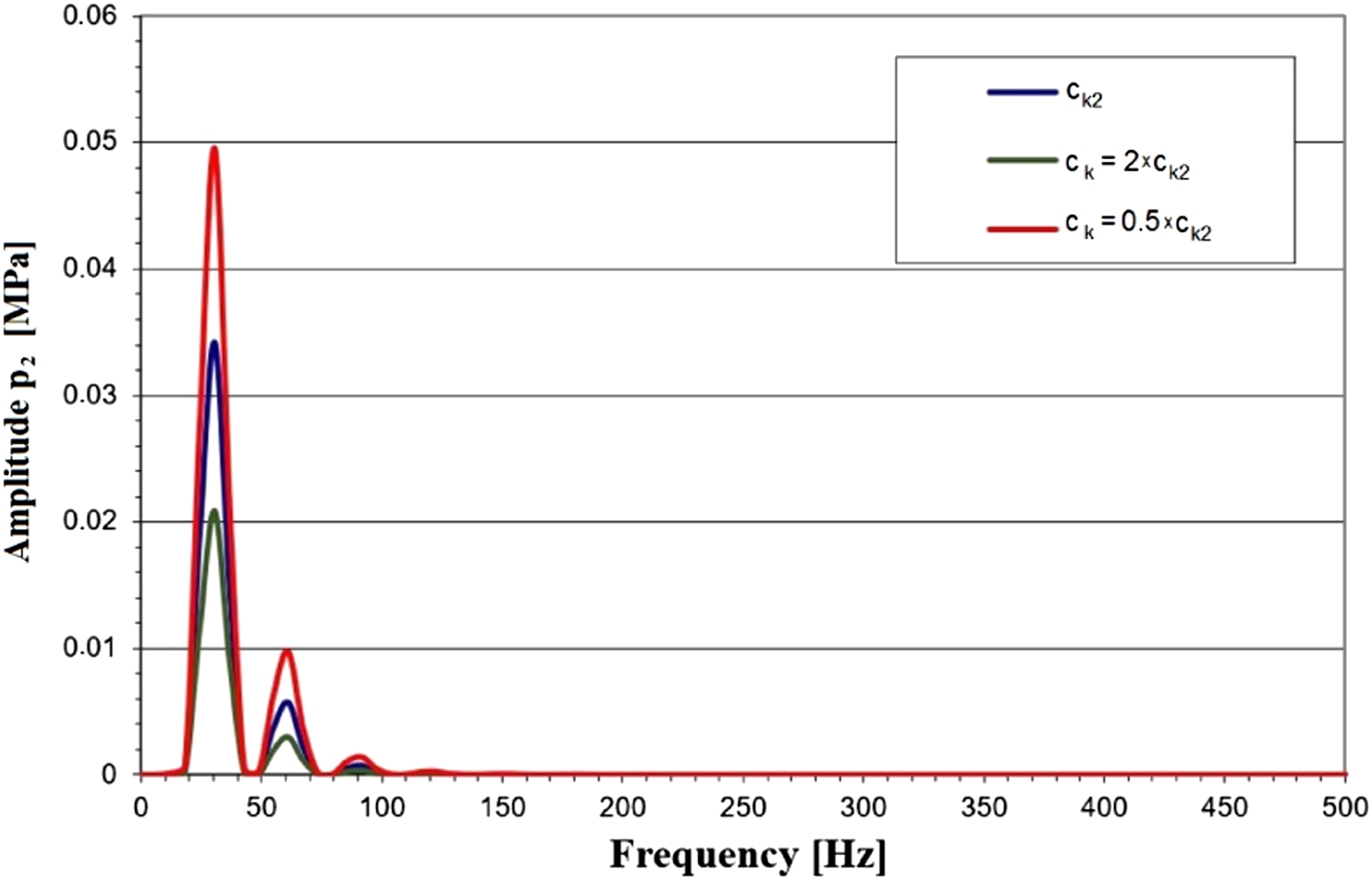
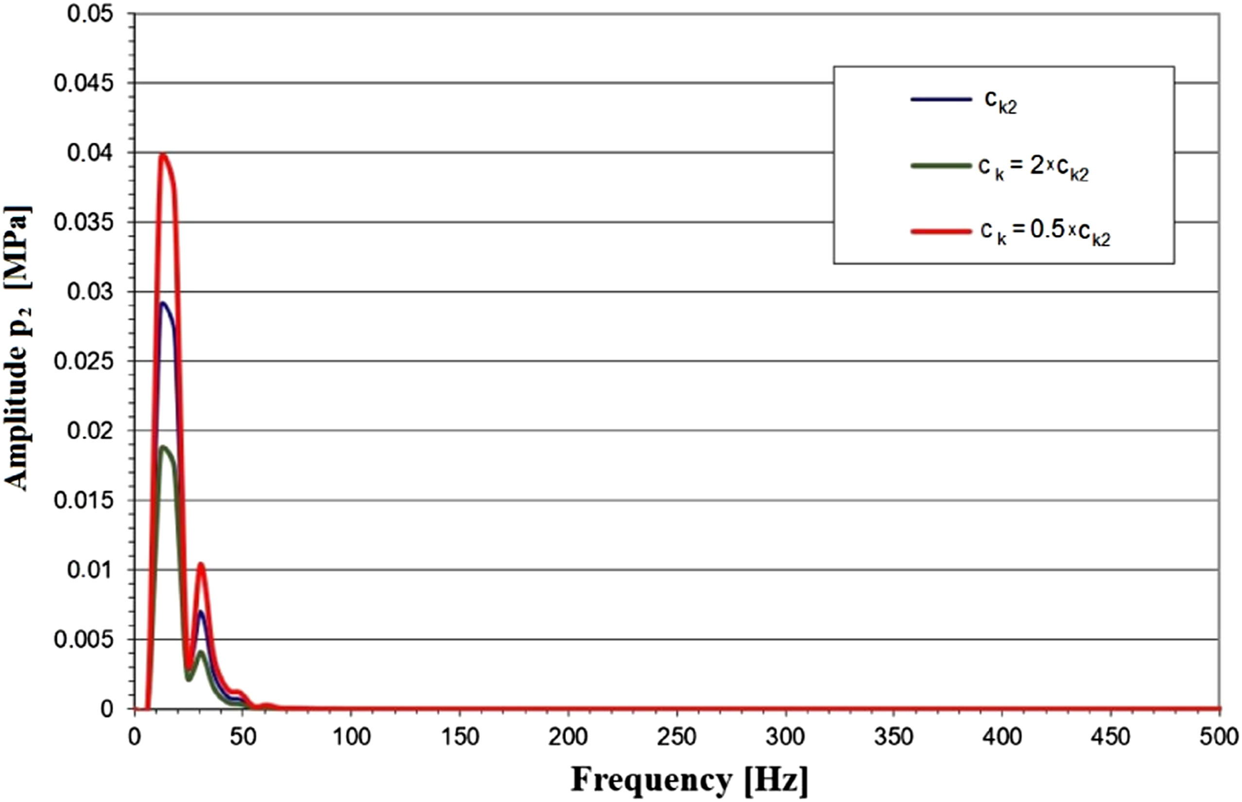
Increasing the capacitance of the hydraulic system from the value of c k2 = 1.55·10−12 [m5/N] to the value of 3.1·10−12 [m5/N] (2c k2 ), a decrease in the value of the amplitude of the pressure pulsation p 2 caused by the external kinematic forcing can be observed. On the other hand, reducing the system's capacitance from the value of c k2 = 1.55·10−12 [m5/N] to a value of 0.775·10−12 [m5/N] (e.g., by reducing the volume of fluid enclosed by the tubes) leads to an increase in the amplitude of this pulsation.
Full identification of the amplitude-frequency spectrum of pressure pulsations in a hydraulic system requires the analysis of pressure pulsations caused by displacement pump capacity pulsations.
3. Pressure pulsation caused by displacement pump kinematics
Performance pulsation causes changes in flow over time, and thus the formation of non-stationary processes in pressure conduits mostly adversely affects the work and operation of hydraulic components and systems. In hydraulic systems, the wave phenomena are called the Hydraulic Long Line (HLL). Hydraulic long lines are conduits in which the longitudinal parameters (resistance R
0
; inertance M
0
; capacitance c
k
) have a significant impact on the dynamic properties of the systems. Pressure pulsation in the hydraulic line due to performance pulsation is described by the HLL model with clustered parameters. It was assumed that the parameters R
0
, M
0
, and c
k
are concentrated at selected points along the axis of the hydraulic conduit (Martí-Calatayud et al., 2018). The application of the model with clustered parameters was possible because the length of the pipe is smaller than the fourth part of the length of the pressure wave propagated in it. The method of determining the pressure pulsation based on the capacity pulsation has the following steps: • Decomposition function Q = Q(t) into harmonic components of the Fourier series; • Determination complex hydraulic impedance of the system for successive harmonics; • Determination amplitudes of individual pressure harmonics as products of amplitudes of efficiency and hydraulic impedances; • Representation of pressure pulsation as a sum of Fourier series terms.
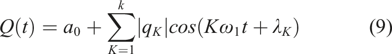
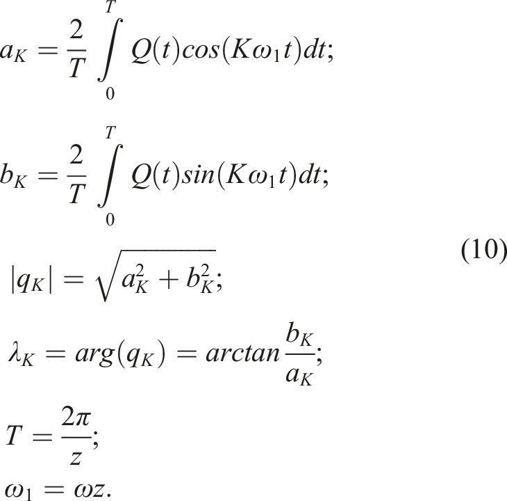
Distribution of the displacement pump capacity pulsation (time course) in the Fourier series can be written in the form of the equation (Piersol and Paez, 2009)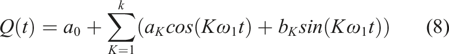
The relationship between harmonic changes in capacity and pressure is determined by the hydraulic impedance Z
k
defined according to the dependence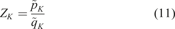
The hydraulic impedance Z
K
is a complex quantity that depends on the structure of the hydraulic system. Assuming harmonic forcing at the beginning of the line in the form of a sinusoidal change in capacity, one can write the relationship between the amplitudes of the harmonic changes in capacity and pressure at the beginning and end of the line (Hoffmann, 1975; Krus, 2019)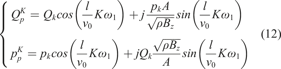
Rearranging equation (12), the hydraulic impedance is obtained in the form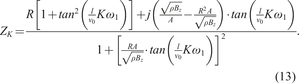
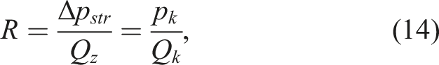
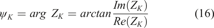
The hydraulic impedance defined by the relation (13) is a complex quantity whose modulus and argument can be defined by the relations
Based on the presented dependencies, the complex amplitudes of individual harmonic waveforms of pressure pulsations were determined
Using the described method of determining pressure pulsations on the basis of capacity pulsations, the course of pressure pulsations was determined for the first harmonic component of the amplitude-frequency spectrum, shown in the Figure 8. The amplitude-frequency spectrum of the pressure pulsation caused by the non-uniformity of pump performance.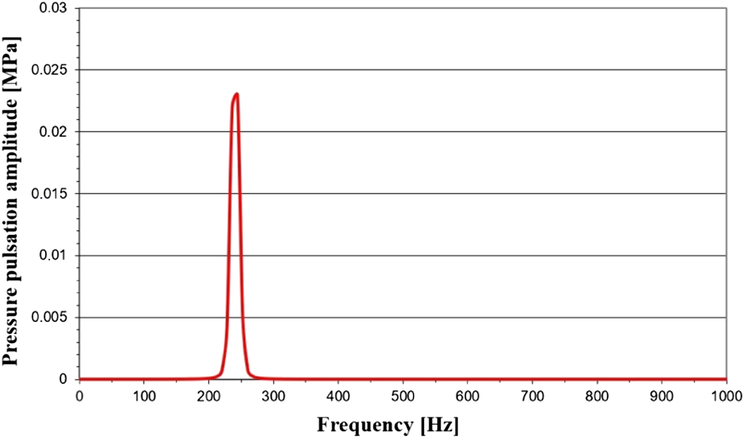
The dominant frequency in Figure 6 is 242 Hz and results from the number of pump displacement elements (9 blades) and the rotational speed on its drive shaft (n p = 1450 rpm).
4. Experimental verification of changes in the pressure pulsation spectrum
In order to verify the conducted considerations, experimental tests were carried out to confirm changes in the pressure pulsation spectrum caused by external mechanical vibrations acting on the proportional directional valve.
4.1. Experimental research
In the experimental tests, a hydraulic system of external forcing in the form of mechanical vibrations acting on the distributor element was used as a simulator of a linear hydrostatic drive realizing reciprocating motion in the frequency range up to 100 Hz, Figure 9(a). During the experimental tests, the following quantities were measured and recorded: amplitude and frequency of vibrations acting on the proportional distributor, relative movement of the distributor slider inside the oscillating valve body, pressure pulsation in the hydraulic system in which the directional valve worked, Figure 9(b). For the set vibration frequency of the hydraulic simulator, the vibrations of the directional control valve body and the pressure pulsation in the hydraulic system were recorded. The frequency of vibration generated by the hydraulic simulator was then changed and the vibration of the directional control valve body and the pressure pulsation in the hydraulic system were recorded again. The vibrations were measured with an accelerometer and the pressure pulsation with a piezoelectric sensor. In this way, a time course of the pressure pulsation was obtained for each selected vibration frequency, followed by a pressure pulsation spectrum. An experimental test bench view: (a) photograph of a hydraulic simulator working as a generator of mechanical vibrations—kinematic forcing acting on the tested hydraulic element; (b) Distribution of measurement points in the test system of the proportional directional valve: 1- pump supplying the test system of the considered element, 2- safety valve, 3- tested proportional directional valve 4WRE 6 E08-12/24Z4/M placed on the simulator table, 4- hydraulic simulator table constituting kinematic input harmonic function for the tested element with the table position measurement point, 5- pressure change measurement point with M101A04 piezoelectric sensor, 6- adjustable throttle valve, 7- measurement of the position of the spool of the directional valve with an inductive sensor.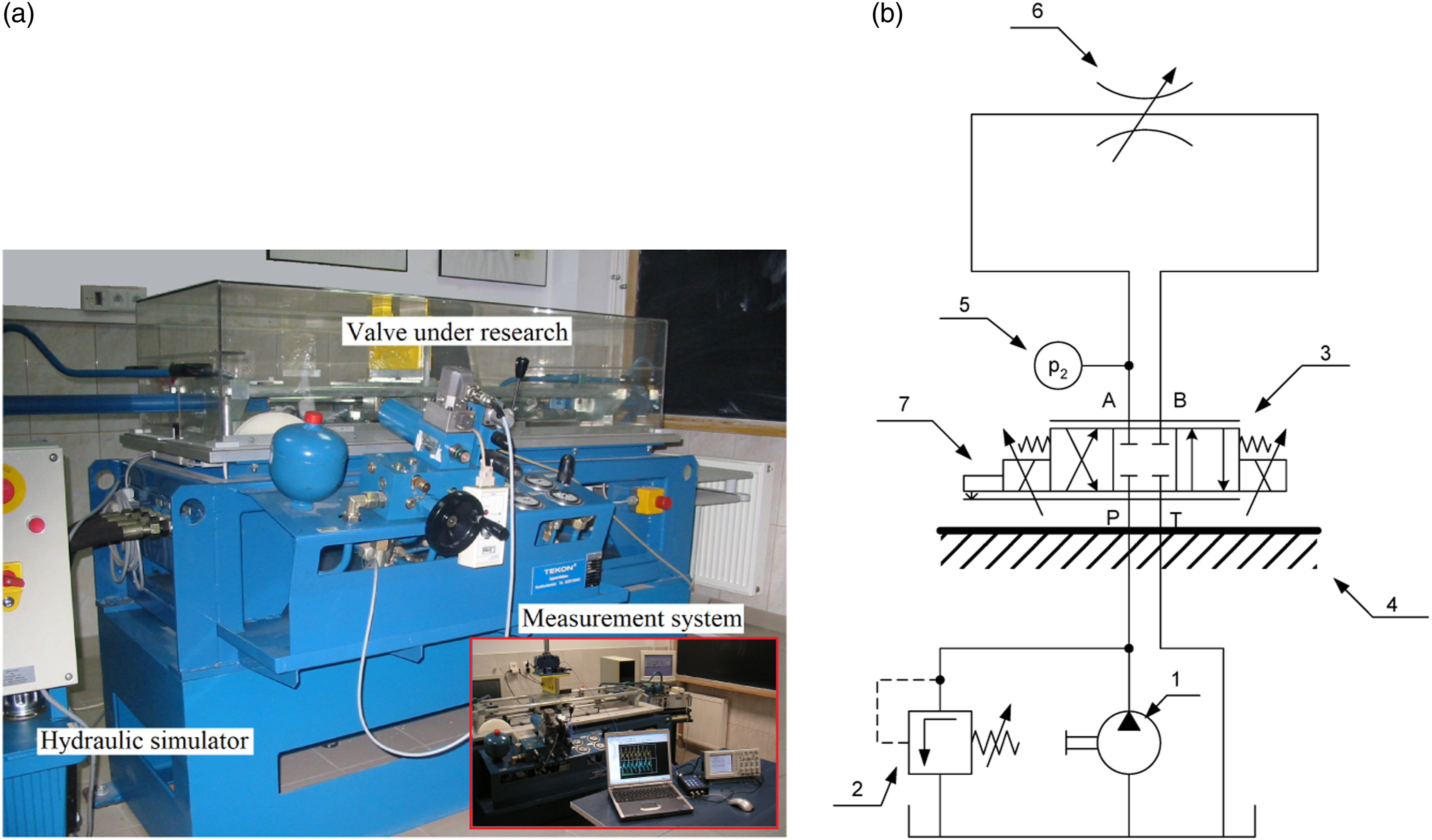
The tested proportional directional valve was subjected to harmonic mechanical vibrations with the amplitude and frequency was given in Table 3. Pressure pulsations were recorded for a given form of external mechanical vibrations. The pulsation of pressure in the hydraulic system of the directional valve was also recorded in the case where the directional valve was not affected by external mechanical vibrations. The results of experimental tests in the form of a collective amplitude-frequency spectrum are shown in Figure 10. The amplitude-frequency spectrum of pressure pulsations in a hydraulic system with a proportional directional valve forced with the different frequencies.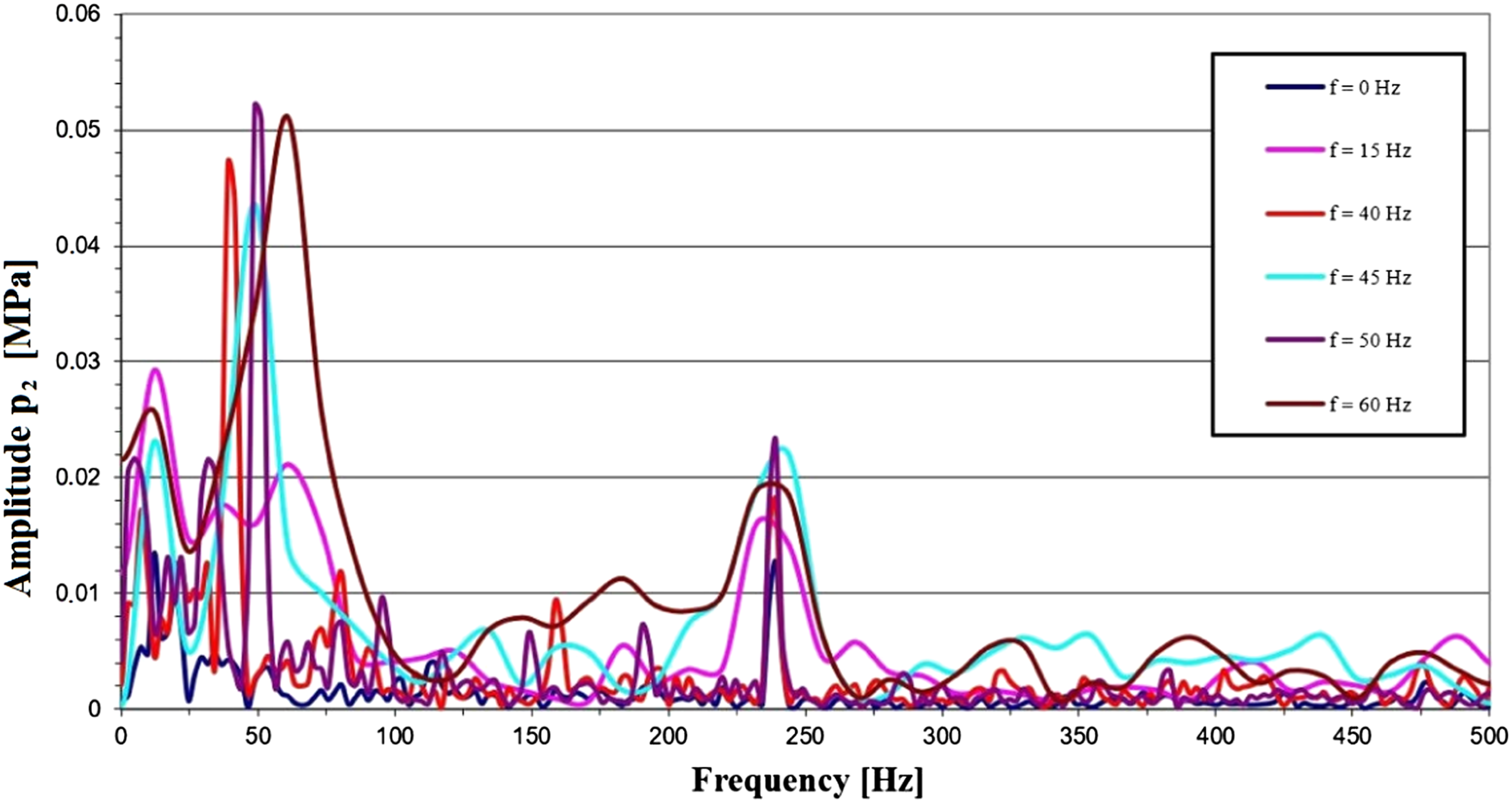
The results presented above (Figure 10) show the influence of external mechanical vibrations on pressure pulsation in the hydraulic system with a forced proportional directional valve. Moreover, it shows that this influence is the greatest for the external forcing frequency f = 50 Hz. Among the components of the amplitude-frequency spectrum of pressure pulsations, there is also a component with a frequency of 242 Hz, which is the result of pulsations of the capacity of the displacement pump supplying the hydraulic system of the tested directional valve. From the results presented in Figure 10, it can be seen that in the range of frequencies analyzed up to 500 Hz, the dominant component of the spectrum is that originating from the kinematic forcing. In the absence of kinematic forcing (f = 0 Hz), the dominant component of the pressure pulsation spectrum is that originating from the pump output pulsation. Moreover, for both the components originating from the kinematic forcing and the performance pulsation, the higher harmonic components of the pressure pulsation spectrum are significantly lower than the first component.
4.2. Comparison results of numerical and experimental researches
In order to assess the correctness of the construction of the model describing the pressure pulsation in the hydraulic system with the kinematically forced proportional directional valve, a comparison of the results was obtained. Figures 11, 12, and 13 show a comparison of pressure pulsations and spool vibrations of the directional valve obtained experimentally and simulated. Simulation solutions were obtained on the numerical solution of models (6) and (17) by superposition of their solutions concerning, respectively, pressure pulsations due to external kinematic extortions and pressure pulsations due to capacity pulsations. Comparison of the amplitude-frequency spectrum of pressure pulsations for the kinematic forcing frequency f = 60 Hz. Comparison of the amplitude-frequency spectrum of pressure pulsations for the kinematic forcing frequency f = 30 Hz. Comparison of the amplitude-frequency spectrum of pressure pulsations for the kinematic forcing frequency f = 15 Hz.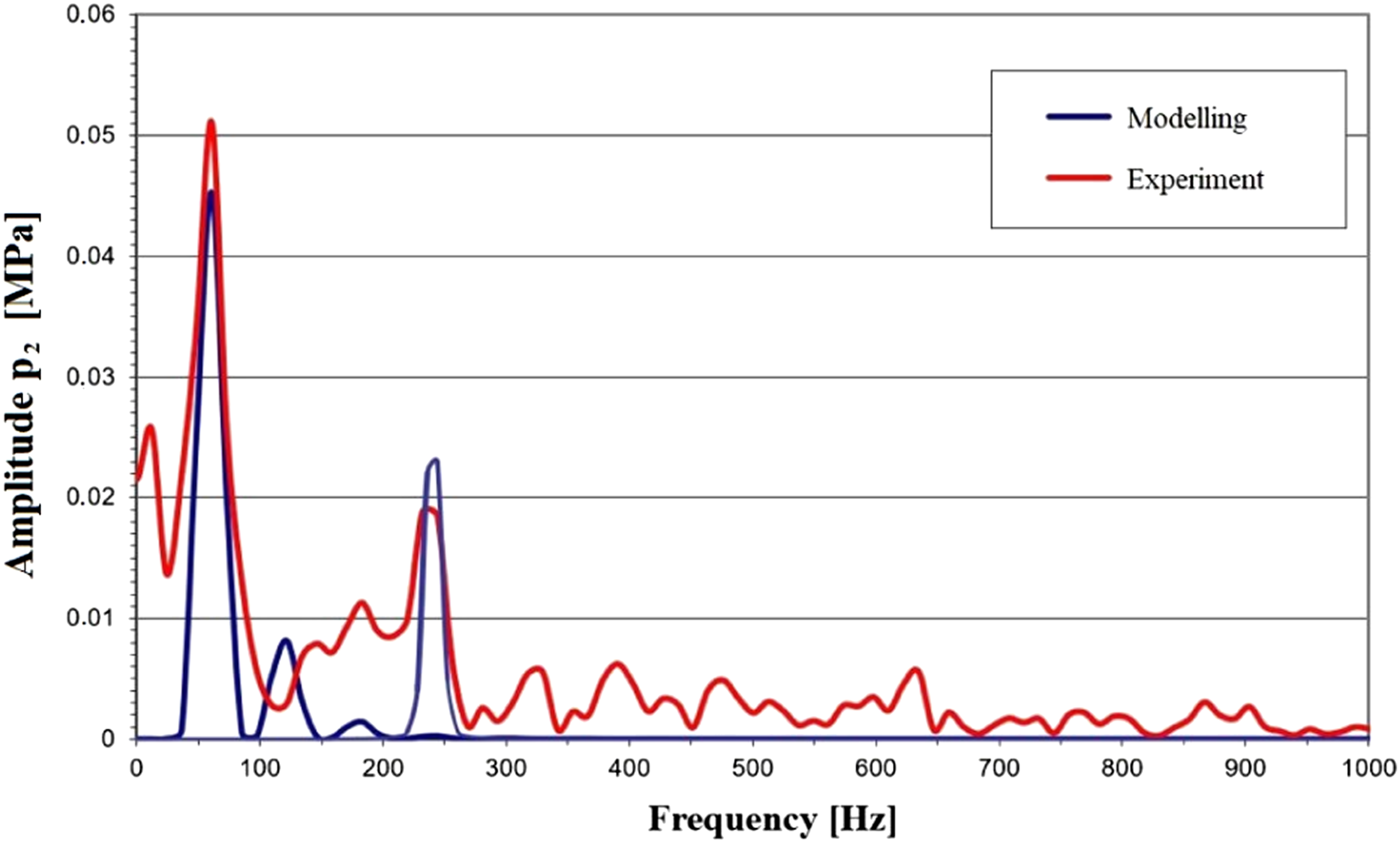

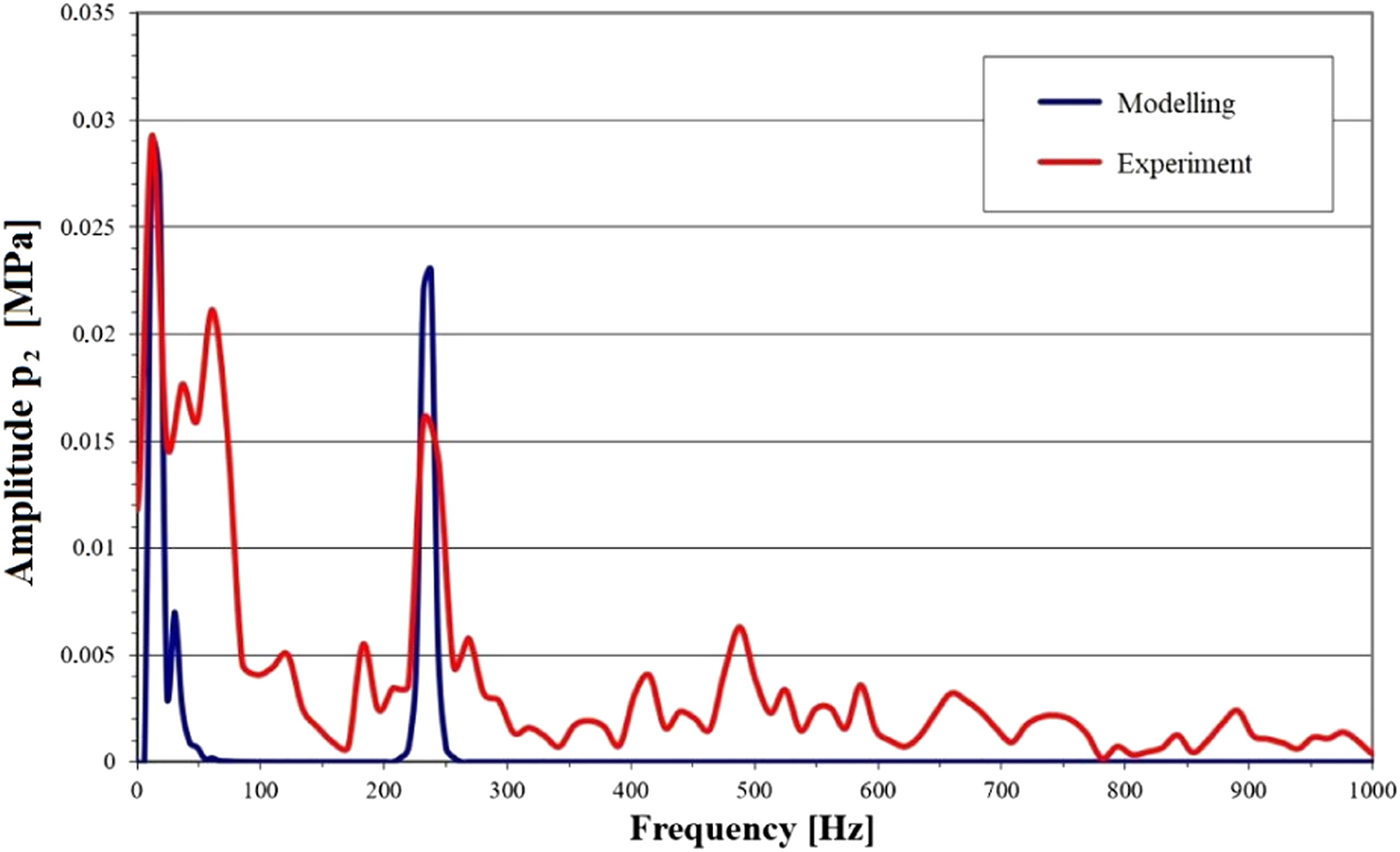
Theoretical waveforms for the amplitude-frequency spectrum of pressure pulsations in the kinematically forced proportional directional valve system correspond in nature and values to the experimental waveforms presented in the form of an amplitude-frequency spectrum in the scope of applied external forcing. Figures 11, 12, and 13 show, among others, the pressure pulsation spectra obtained during the experimental tests. It can be seen that these spectra have, in addition to components due to kinematic forcing and pump performance pulsations, other components that may be due to imbalances in the drive shaft of the positive displacement pump or wave phenomena in the hydraulic hoses.
5. Conclusions
The following conclusions can be drawn from the comparison of experimental and simulation runs: a good agreement was obtained: between the experimental and theoretical runs describing the pressure pulsation in the hydraulic system with kinematically forced proportional directional valve; for the fundamental component of the pressure pulsation spectrum resulting from the displacement pump capacity pulsation; of the pressure pulsations by the theoretical model is of particular importance because the course of pressure (together with its harmonic components) in the system determines the operation of the entire system and, in particular, affects the operation of hydraulic actuators and the generated noise level and forcing of vibrations of other elements of the hydraulic system. (e.g., hydraulic lines).
As has been shown in experimental studies, there are frequencies of external forcing at which an increase in the amplitude of pressure pulsations in the hydraulic system is observed. The reasons for this phenomenon should be sought in the value of the natural frequency of the hydraulic valve control elements. This observation can be generalized to hydraulic valves, in which the mass of the vibrating element and the stiffness of the associated system have a decisive influence on the natural frequency. In the case of the considered proportional directional valve, in which the spool is overridden due to the forces exerted by the proportional electromagnet coils, the mass of the vibrating element (the spool together with 1/3 of the spring mass) and the equivalent stiffness of the spring system will have a decisive impact on the natural frequency of the spool. The proposed description of the motion of the vibrating spool allows to analyze the effects of the capacitance change on the value of the pressure pulsation amplitude. An increase in the capacitance of the system causes a decrease in the value of the pressure pulsation amplitude, which is a favorable phenomenon. The influence of other parameters of the hydraulic system, such as the viscosity of the hydraulic oil, can be tested.
Footnotes
Declaration of conflicting interests
The author(s) declared no potential conflicts of interest with respect to the research, authorship, and/or publication of this article.
Funding
The author(s) received no financial support for the research, authorship, and/or publication of this article.