
Abstract
Tunnel boring machine (TBM) is seriously damaged during tunneling due to excessive vibration. Insufficient research on the TBM vibration mechanism has led to low accuracy in the calculation of the dynamic response of the TBM main drive system under uncertain load. In this paper, multi-degree-of-freedom coupled dynamics model of the main drive system containing the cutterhead, gear drive, shield, and propulsion system was established, taking bearing and drive gear nonlinear contact forces, uncertain load into account. A multi-position vibration test was carried out based on practical engineering. The vibration mechanism and vibration transmission law along the main structure are studied. The results show that the frequency response of the cutterhead presented a wide frequency domain bandwidth. The main frequency band of support shell is concentrated at 18–20 Hz, which is mainly caused by the excitation of the first three-order natural frequencies of the system under the action of the system’s broadband external excitation load. At the same time, it is found that the coupled vibration of radial overturning vibration and lateral translation vibration is easy to appear in the actual system vibration. The influence of the main mass and stiffness parameters of the system on the various modes of the system is analyzed. The overturning vibration of the shield body has a significant “amplification effect,” and its amplitude reaches 123.60% and 118.99% of the cutterhead, respectively. This study provides a basis for the system’s dynamic design and evaluation of the TBM performance in tunnel construction.
Introduction
In the process of tunneling, TBM bears impact loads. At the same time, the internal subsystems such as cutterhead, transmission system, propulsion system, and support system interact with each other, which makes the dynamic characteristic of the system extremely complex. It is difficult to predict the vibration law of each key part during the excavation process, which directly affects the overall stability and excavation performance of the main drive system. This easily leads to a series of failures of key components of the TBM main drive (such as large-scale cracking of the cutter head body, fracture of connecting bolts, failure of bearing seals, etc.), 1 resulting in serious engineering problems. Therefore, studying the dynamic characteristic and mechanism of the TBM main drive system under the coupling action of multiple subsystems is the basis for effective dynamic performance design.
The rock breaking load of TBM cutterhead provides external excitation for studying the dynamic characteristics and transmission laws of the main drive system, which is the basis for studying the dynamic characteristics of TBM main drive system. It directly affects the accuracy of system dynamic characteristic calculation. 2 The research on the rock breaking load of rolling cutters mainly focuses on three directions: obtaining the load from laboratory rolling cutter rock breaking experiments, 3 numerical model simulation, 4 and on-site measurement of rolling cutter rock breaking load. 5 In order to solve severe vibration problem of key components of the TBM main drive system and reveal the complex dynamic behavior of the system under impact load, scholars mainly study by establishing dynamic model of the main drive system and analyzing the relevant dynamic responses. Scholars6,7 have established a dynamic model of the TBM main drive system based on gear dynamics and bearing dynamics in order to explore the dynamic characteristics of internal vibration loads and other dynamic features of the system. Gear dynamics is an important part of the dynamic modeling of TBM main drive systems to study their load sharing and meshing characteristics under strong sudden loads. Kahraman and Singh8,9 established a 3-degree-of-freedom bending torsional coupling dynamic model for gear pairs, taking into account the time-varying mesh stiffness and tooth flank clearance of the gear pairs, as well as the coupling relationship between the bending and torsional vibration directions of the gears, and analyzed their nonlinear vibration response. Based on this gear model, Sun et al.10,11 established a multi-degree-of-freedom coupled dynamic model of the TBM cutterhead system, considering the dynamic meshing stiffness of gear teeth and bearing stiffness. After that, Zhang et al.12,13 based on the above dynamic model, used the finite element method to model the main drive system drive shaft subsystem, and finally used a hierarchical dynamic modeling method to model each subsystem of the TBM. The model is more accurate in analyzing the dynamic characteristics of the synchronous drive transmission system. Since the support propulsion system plays a major role in supporting the TBM, its dynamic characteristics significantly affect the vibration and attitude of the main drive system of the TBM during the excavation process. Therefore, based on the dynamic model of the TBM drive system, scholars further established the dynamic model of the TBM main drive support propulsion system. Liao et al. 14 considered the closed-chain and kinematic relationship of the TBM support system, and established a dynamic model of the support propulsion system. By using the CSM formula to calculate the equivalent external load, the model can study and analyze the attitude of the system under different surrounding rock conditions and the support state of each cylinder. Huo et al.15,16 established a multi-degree-of-freedom coupling model of the TBM main drive system from the cutter head to the main beam, and measured the vibration of the cutter head of the main drive system. However, only the main bearing direction of the axial direction is considered. Zou et al. 17 established a dynamic model for the open TBM main drive system. Based on this, the vibration energy of the system under different penetration degrees and rock types is studied. However, the model mainly considers the three-dimensional translation degrees of freedom of the system, so it is difficult for the model to study and analyze the unbalanced overturning vibration that the system bears during the actual excavation process.
Based on the above-mentioned dynamic model of the TBM’s main drive system, scholars have conducted a lot of research on the inherent characteristics of the system and the dynamic characteristics under impact load. Ling et al. 18 obtained the modal energy distribution of each system on the basis of a multi-degree-of-freedom coupled dynamics model, further distinguished the modal vibrations of each order, identified the modal sensitive parameters. Wu et al. 19 analyzed the load characteristics of the main components of the system based on an equivalent dynamic model of the TBM main drive system. Also Huo et al. 20 further used interval uncertainty theory to describe the uncertainty of strati-graphic parameters, combined with a dynamic model to analyze the vibration characteristics of TBMs in composite rock formation, and explored the influence of the ratio of soft and hard rock on its vibration characteristics. Xia et al. 21 studied the vibration frequency band of the support propulsion system based on a multi-body dynamic simulation platform. Then a field vibration of the TBM support propulsion system was measured. The results show that the vibration of its main beam part was dominated by axial vibration.
In summary, for the study of the dynamic behavior of the TBM main drive system, scholars have mainly studied and analyzed the inherent and dynamic characteristics of the system based on the drive system dynamic model. Existing dynamic models and vibration measurements are not systematic enough to determine the dynamics of the main drive system with reasonable accuracy. Existing studies can only roughly calculate the vibration level, and there is insufficient research on the vibration mechanism and variation law of the TBM system. This has led to difficulties in TBM systems’ dynamic design to effectively solve the severe system vibration.
The aim of this paper is to establish a multi-degree-of-freedom coupled dynamic model of the main drive system containing the cutterhead, gear drive, shield, and propulsion system based on the structural characteristics. Meanwhile, internal excitations such as bearing and drive gear nonlinear contact forces are also considered. The vibration characteristics of the main drive system were measured at multiple points of the whole machine to verify the accuracy of the dynamic model. The vibration transmission law and vibration mechanism of the dynamic system under typical external load are studied based on the dynamic model.
Methods and materials
Modeling of TBM main drive system dynamics
A typical TBM main drive system is shown in Figure 1. It consists of a cutter system, main drive system, shield system, and support propulsion system. The main drive system and the support propulsion system are cemented together by flanges at the front section of the main beam, and the support propulsion system provides axial support for the entire main drive system. Through the coordinated action of the main drive system and the support propulsion system, the TBM completes the rock-breaking action.22,23

The structure diagram of TBM main system.
Equivalent dynamic model of TBM main drive system
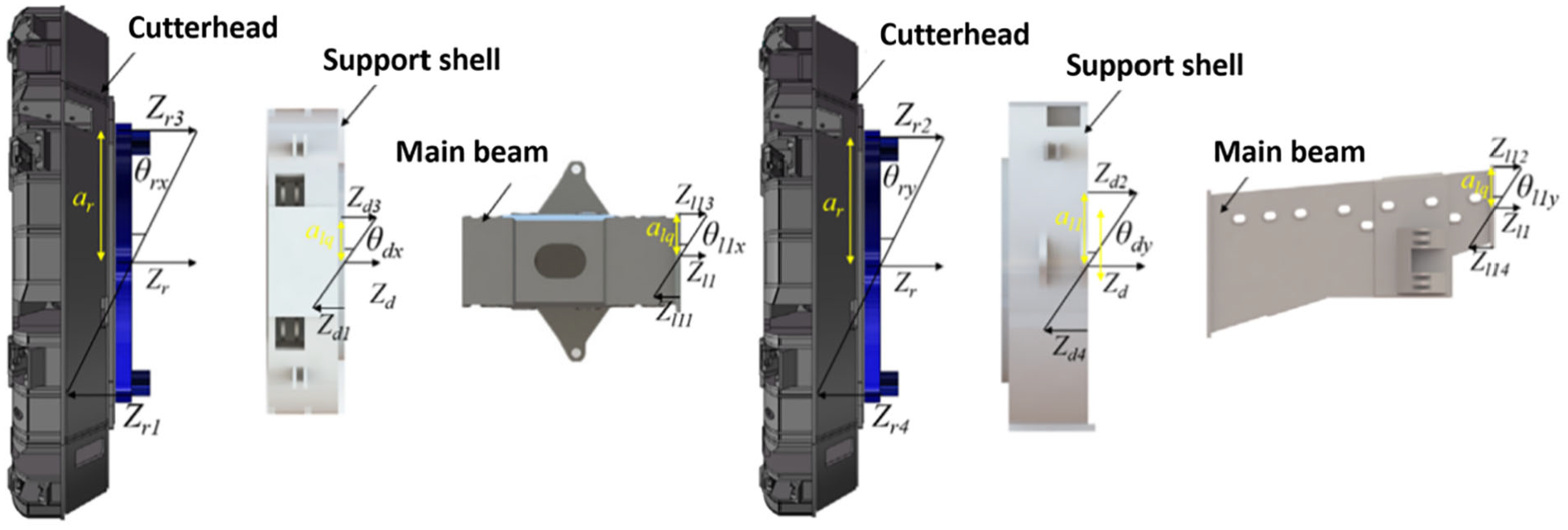
Based on the multi-source drive mode and support structure of the TBM main drive system, the multi-degree-of-freedom coupling dynamic model of the TBM main drive system is established, as shown in Figure 2. The model mainly considers the translational and torsional degrees of freedom in the axial, horizontal, and vertical directions of the system. The model is established by the concentrated mass method, and the particle division mainly includes the cutter head-large ring gear, the support shield, the driving gears, the front section of the main beam, the middle section of the main beam, and the saddle. The mass points of the system are related to each other through nonlinear loads and spring damping elements. The large gear ring and the support shell are connected by bearing contact force. The driving gears and the large ring gear are connected by the meshing force of the gear teeth. The propulsion force between the main beam and the saddle is through the propulsion cylinder. The support shell and the surrounding rock are connected by contact force. The multi-source input load of the model is mainly reflected in two parts, one is the axial force, radial force, overturning moment and torque at the cutter head, and the other is the dynamic driving torque input by each drive motor. In the model, Fx, Fy, Fy are the horizontal, vertical, and axial equivalent loads on the cutter head. Tpi is the output torque of the ith motor. TL is the equivalent total torque that the cutter head bears. Mx, My are the horizontal and vertical overturning moments of the cutter head. Xj, Yj, Zj, θj, θjx, θjy represent the horizontal displacement, vertical displacement, axial displacement, torsional displacement, horizontal overturning displacement, and vertical overturning displacement of the j component, respectively. m and I represent the equivalent mass and moment of inertia of each component. j = r, d, l1, l2, c, pi, mi represent the cutter head, the main drive support frame, the front section of the main beam, the middle section of the main beam, the ith drive gear of the saddle, and the ith drive motor, respectively.

Dynamic model of TBM main drive system. (a) Main drive system dynamics model (horizontal direction). (b) Main drive system dynamics model (vertical direction). (c) Transmission system dynamics model (horizontal and axial directions). (d) Dynamic model of saddle and gripper shoe (axial direction).
The stiffness and damping of each component in the dynamic model are shown in Table 1. The dynamic parameters are calculated according to references. 11
Main parameters of stiffness and damping in dynamic model.

The coupling relationship of each degree of freedom of the system
The relationship between the bending and torsional degrees of freedom of the large ring gear and the pinion
When the main drive system is working, each pinion synchronously drives the large ring gear to rotate. According to the structure of the main drive system, the drive mode can be divided into internal meshing form and external meshing form. When the gear drive is external meshing. The relative displacement relationship between the pinion gear and the large ring gear is shown in Figure 2(c).
The relative elastic deformation xpri between the large ring gear and the pinion is:

Where ur and upi are the displacements of the large ring gear and the pinion on the meshing line. Xr, Yr, Xpi, and Ypi are the horizontal and vertical displacements of the large ring gear and the pinion; α and φi are the meshing angle and phase angle of each small gear.
The equivalent meshing error of the large ring gear and the pinion on the meshing line is:

Where Er, Ar, εr, σr are the manufacturing error, installation error, tooth thickness deviation, and tooth profile error of the large ring gear. Epi, Api, εpi, σpi are manufacturing error, installation error, tooth thickness deviation, and tooth profile error of the pinion. βr, γr, βpi, γpi are the phase angles of each error. ωr and ωp are the angular velocity of the large ring gear and the pinion.
The time-varying meshing force Fpri and the time-varying meshing damping force Dpri of the gear are:


where kpri(t) and cpri(t) are the time-varying meshing stiffness and damping of each pinion, f(xpri, b) is the non-linear meshing clearance function.

Where the backlash of the gear pair is 2b, and xpri is the dynamic relative displacement of each gear pair along the meshing line.
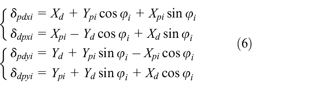
In the dynamic model, δpdxi, δpdyi, δdpxi, δdpyi are the horizontal and vertical displacements of the i-th drive gear and the support frame, respectively. The calculation method is shown in the equation (6).
Relative displacement relationship of propulsion system
The bending, axial, and overturning coupling relationship of the support system is mainly used to describe the relative positional relationship between the front section of the main beam and the gripper shoe, and the relative displacement relationship is shown in Figure 3. Since the TBM gripper shoe can be equivalent to a stationary state along the driving direction, only the horizontal direction of the gripper shoe cylinder is considered in the dynamic model. Its relative relationship with the middle section of the main beam is shown in Figure 3.Where the intermediate variables xl1cy1 and xl1cy2 are the relative elastic deformation of the main beam’s front section and the gripper shoe, and the calculation method is shown in equation (7).

Where β1 is the support angle of the main propulsion cylinder, and al1m is the projected distance from the center of mass of the front section of the main beam to the support direction of the main propulsion cylinder.

The relative displacement relationship.
The intermediate variables δl2c1 and δl2c2 are the relative displacements of the main beam’s middle section and the saddle, respectively, as shown in formula (8).
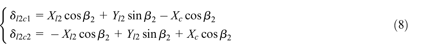
Where Xl2, Yl2, Xc, Yc are the horizontal and vertical displacements of the middle section of the main beam and the saddle, respectively, and β2 is the support angle of the anti-twist cylinder.
Overturning-axial displacement relationship of main drive system
The relative relationship between the overturning displacement and the axial displacement of the cutter head, support shell, and main beam is shown in Figure 4.
Axial-overturning relationship of the main system.
The intermediate variable Zri (i = 1–4) is the axial displacement of the lower, left, upper, and right positions of the cutter head. Zdi (i = 1–4) is the axial displacement of the lower, left, upper, and right positions of the shield. Zl1i (i = 1–4) is the axial displacement of the lower, left, upper, and right positions of the front section of the main beam.

Where ar is the radius where the axial thrust roller of the bearing is located, al1 is half the length of the shield body’s flange and the front main beam, and alq is half the width of shield body’s flange and the front main beam.
Establishment of system dynamics differential equations
According to the dynamic equivalent model and the relative displacement relationship of each part, the dynamic equations corresponding to the dynamic model of the TBM main drive system are shown in equations (10) to (13).
For cutterhead:

For drive gears and motors:
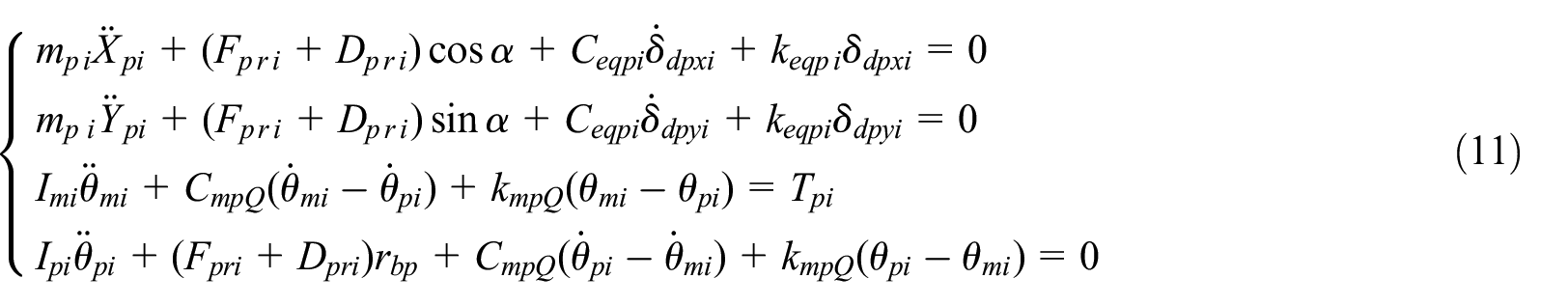
For shield body:

For main beam:

Multi-point vibration measurement of TBM main drive system
As the vibration of the cutter head part is the strongest. The lower part of the cutter head often has the presence of water. The installation position of the sensor will obvious influence its normal operation. The location of the sensor on the TBM’s cutterhead is shown in Figure 5(a) and (b). The acceleration sensor in the shield part is placed behind the bearing ring as shown in Figure 5(c), and the sensor in the front part of the main beam is placed in the place where the main beam and the support shield are connected. The environmental rock parameters, excavation parameters, and main support state parameters of the system during the vibration measurement process as shown in Table 2.
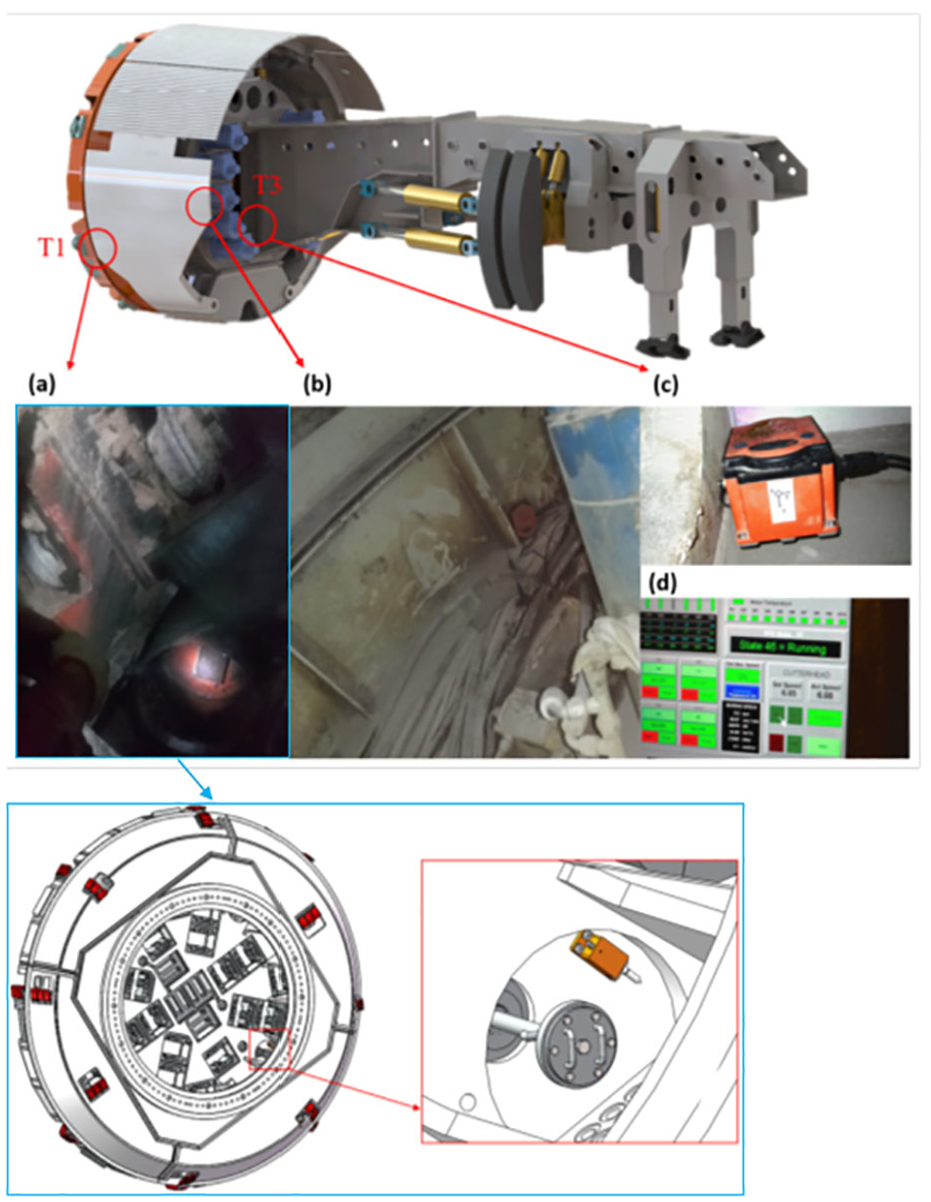
Layout of cutterhead acceleration sensor and test diagram: (a) cutterhead T1, (b) support shell T2, (c) main beam T3, and (d) tunneling parameters.
Main driving parameters in vibration measurement.

Results
Equivalent load of cutterhead
The load of the cutter at each position of the cutterhead is synthesized to obtain the equivalent load of the cutterhead as shown in Figure 6.

Equivalent load of cutterhead.
From Figure 5, it can be seen that the dynamic loads of the cutterhead exhibit significant abrupt changes in all directions, among which the transverse and longitudinal overturning moments and the transverse and longitudinal unbalanced loads also show obvious periodic variation characteristics, with the variation period consistent with the rotation period of the cutterhead. After statistical analysis, the RMS values of axial load and torque were 5610.9 kN and 2872.2 kNm, respectively, with maximum amplitudes of 1448.1 kN and 190.2 kNm, respectively; The RMS values of its horizontal and vertical unbalanced loads are 192.1 and 164.2 kN, respectively, with maximum amplitudes of 637.7 and 480.1 kN, respectively; The RMS values of its transverse and longitudinal overturning moments are 1723.0 and 1763.0 kN, respectively, with maximum amplitudes of 3250.9 and 3388.3 kNm, respectively.
Vibration characteristics of main drive system
In the dynamic model of the main drive system, the structural stiffness of the front and middle sections of the main beam is calculated by the finite element method. The dynamic parameters to be modified mainly include the structural stiffness of the front and middle sections of the main beam. The estimated range of each stiffness is shown in equation:

In order to improve the calculation accuracy of the coupled model for the system vibration response, the main structural stiffness of the TBM main drive was modified based on the excavation data of the field test. The optimization process takes the minimum error between the vibration response RMS value of the dynamic model and the test data as the optimization goal. The optimization method adopts the Hooke-Jeeves method (K and M, 1997; Table 3).
Modified TBM structure stiffness parameters.

After the model is modified, the three-directional vibration of the cutter head, support shield, and main beam of the system is calculated based on the coupled dynamics model, and the comparison with the measured vibration data of each component is shown in Figure 7 and Table 4.

Comparison between vibration test data and calculation value. (a) Axial acceleration of the cutterhead. (b) Horizontal acceleration of the cutterhead. (c) Vertical acceleration of the cutterhead. (d) Axial acceleration of support shell. (e) Horizontal acceleration of support shell. (f) Vertical acceleration of support shell. (g) Axial acceleration of main beam. (h) Horizontal acceleration of main beam. (i) Vertical acceleration of main beam.
Test data and calculated value statistics.

As shown in Figure 7, the maximum errors of the RMS values of the three-directional vibration at the specific position of the TBM cutter head, the support shield, and the front section of the main beam are within 18%, 21% and 22%, respectively.
The frequency response data corresponding to the main vibration directions of the cutter head, the interface between the support shell and the main beam are extracted. It was compared with the frequency domain response calculated by the dynamic model, as shown in Figure 8.

Frequency domain of vibration test data and calculation value: (a) axial acceleration of the cutterhead and (b) axial acceleration of support shell.
It can be seen that the axial acceleration frequency domain response of the cutter head is a typical broadband frequency domain vibration, which is caused by the uncertain load of the surrounding rock in the front section during the field excavation process. The vibration distribution of the measured frequency domain response is relatively uniform in the frequency domain of 0–80 Hz, and shows a slightly larger proportion in the frequency domain of 20–30 Hz and 50–60 Hz. But the calculated frequency domain response of the dynamic model shows a slightly larger proportion of vibration at frequencies of 10–15 Hz, 25, 42, 50, and 62 Hz. This frequency domain response is very close to the frequency domain response of the axial equivalent load of the cutterhead, 19 so the vibration of the cutter head is mainly reflected as the forced vibration of the system under the external excitation load.
The vibration test part of the support shield is located at the connecting flange between the support shield and the front section of the main beam. The frequency-domain response of the axial vibration acceleration is obviously concentrated around 18–20 Hz, and it also shows larger vibration at 25–30 Hz. The main frequency band of the frequency domain response of vibration acceleration at this position calculated by the dynamic model is concentrated around 17.4 Hz. From the analysis of the natural frequency of the system in section “Inherent characteristics of main drive system and multi-parameter influence analysis” of this paper, it can be seen that it is the first order natural frequency of the system, and its corresponding mode shape is horizontal overturning vibration. The main frequency band of the system is relatively consistent with the measured frequency domain response.
Inherent characteristics of main drive system and multi-parameter influence analysis
Analysis of inherent characteristics of main drive system
The first 10 natural frequencies of the TBM main drive system and the corresponding modes are shown in Figure 9. It can be seen that the first-order mode of the system is 17.44 Hz, which is dominated by the horizontal overturning vibration of the system, accompanied by the horizontal translation vibration of the system. The second-order and third-order modes are 19.23 and 21.39 Hz, respectively, and are dominated by overturning vibration. The first three modes of the system are similar, and the coupled vibration of the first to third modes is easy to occur in the actual vibration. The mode is the coupled vibration of the overturning vibration in each direction and the horizontal translation vibration. The natural frequency corresponding to the axial mode is the highest, followed by the vertical translation mode, and the natural frequency corresponding to the horizontal mode is the smallest. Therefore, the rigidity of the system is the highest in the axial direction, followed by the vertical direction, and the smallest in the horizontal direction.

Mode corresponding to natural frequency of the system.
Multi-parameter analysis of natural frequency
Equivalent support stiffness of main propulsion cylinder
The main propulsion cylinder plays a major role in supporting the axial direction of the system and provides the power required for the axial movement of the system. The relationship between the equivalent support stiffness of the cylinder and the natural frequency of the system is shown in Figure 10(a).

Relationship between propulsion cylinder stiffness and natural frequency.
In the figure, Xi, Yi, and Zi represent the natural frequencies corresponding to the i-th horizontal, vertical, and axial translational vibration modes of the system, respectively. θxi and θyi represent the natural frequencies corresponding to the i-th horizontal and vertical overturning vibration modes of the system, respectively.
It can be seen that with the increase of the equivalent support stiffness of the main propulsion cylinder, the corresponding natural frequencies of the first-order and second-order horizontal overturning modes of the system show a significant increasing trend. When the equivalent support stiffness is about 1e9 N/m, the phenomenon of modal superposition occurs, and the coupled vibration of horizontal and vertical overturning vibration occurs. Within the overall range of equivalent stiffness changes, the natural frequency of the first-order axial vibration of the system shows a relatively obvious increasing trend. At the same time, the natural frequency corresponding to the first-order vertical translation vibration of the system does not change significantly.
Equivalent support stiffness of shield body
It can be seen from Figure11(b) that the equivalent support stiffness of the shield body has a significant influence on the second-order horizontal overturning mode and the first-order horizontal and vertical translation mode of the system. When the equivalent support stiffness of the shield is greater than 8e8 N/m, the second-order horizontal overturning mode increases significantly.

Relationship between main bearing support stiffness and natural frequency: (a) main bearing axial stiffness and (b) main bearing radial stiffness.
Equivalent support stiffness of main bearing
The main bearing of TBM is the main bearing structure of the system. The relationship between the equivalent axial and radial equivalent stiffness of the main bearing and the system mode is shown in the Figure 11.
It can be seen that the natural frequencies of the first-order overturning vibration modes show a significant increasing trend. In the range of 1e8–3e8 N/m, the two modes show the phenomenon of mode separation, and in the range of 3e8–1e9 N/m, the two modes show the trend of mode overlap. The equivalent axial stiffness of the main bearing has a great influence on the various order modes of the system, especially on the axial translation vibration and overturning vibration modes of the system.
The modal energy analysis of the system
On the basis of system modal analysis, we have analyzed the modal energy of the system. The specific analysis is as follows. The kth mode kinetic energy Wi and mode deformation energy Ei of the main drive system are expressed as follows:

Where ωk is the kth natural frequency, K and M are the stiffness matrix and mass matrix of the system, respectively, and {φ} k is the principal mode vector corresponding to the kth natural frequency.
The modal deformation energy of each component is shown in Figure 12. From Figure 12, it can be seen that the total deformation energy of the TBM main drive system is mainly concentrated in the first 10 modes of the system. When the modes are greater than 10, the deformation energy of the system is very low, indicating that the deformation degree of the system is relatively large during low-frequency vibration. In the first 10 natural frequencies, the natural frequencies corresponding to the transverse and longitudinal overturning vibration of the first and second orders also exhibit higher total system deformation energy. The modal deformation energy corresponding to the lateral overturning vibration mode is the maximum supported by the shell. At the same time, the natural frequencies corresponding to axial vibration and longitudinal overturning vibration in the 7th to 10th order also exhibit high modal deformation energy. The deformation energy of the cutterhead is the highest, followed by the supporting shell, and the main beam is the smallest.

Modal deformation energy distribution. (a) The modal deformation energy of cutterhead. (b)The modal deformation energy of shield. (c) The modal deformation energy of main beam. (d) Proportion of modal deformation energy.
The modal kinetic energy of each component is shown in Figure 13. From Figure 13, it can be concluded that the total modal kinetic energy of the system is mainly concentrated in the first 10 modes of vibration of the TBM main drive system. The total kinetic energy is mainly concentrated in the transverse and longitudinal overturning modes of order 1–2 and the axial translation and longitudinal overturning modes of order 8–10. The total kinetic energy of the torsional vibration modes of the third and fifth order systems along the excavation direction is not significant. In its first-order lateral overturning mode, the kinetic energy of the supporting shell accounts for the largest proportion. In the first order axial translational vibration mode, the kinetic energy of the cutterhead accounts for the largest proportion.

System modal kinetic energy distribution. (a) The kinetic energy energy of cutterhead. (b) The kinetic energy energy of shield. (c) The kinetic energy energy of main beam. (d) Proportion of modal kinetic energy.
Sensitivity analysis of system dynamic parameters
Sensitivity analysis of cutterhead mass
This paper analyzes the sensitivity of the mass of the cutterhead to system vibration. The mass range varies from 80% of the original mass to 120%, and the analysis results of the three-dimensional vibration amplitude and RMS value of each component are shown in the following Figure 14.

Relationship between cutterhead quality and cutterhead vibration. (a) The relationship between cutterhead mass and vibration RMS value. (b) The relationship between cutterhead mass and vibration amplitude.
It can be seen that during the process of the mass of the cutterhead changing from 80% of the original mass to 120%, the RMS value of the cutterhead’s translational vibration has undergone significant changes. As the mass coefficient of the cutterhead increases, the RMS value of its translational vibration shows a significant downward trend in the mass coefficient, and the rate of decrease is similar. During the process of increasing the mass coefficient of the cutterhead from 0.8 to 1.2, the RMS value of its axial vibration decreased by 29.5%, and the RMS values of its transverse and longitudinal vibrations decreased by 36.9% and 36.2%, respectively. The amplitude of its isotropic translational vibration also shows a significant decreasing trend, with the axial vibration amplitude of the cutterhead decreasing at a similar rate within the overall range of mass coefficient variation. When the mass coefficient reaches 1.2, the vibration amplitude decreases by 33.0%. The lateral vibration amplitude shows a continuous decreasing trend during the process of changing the mass coefficient, and the decreasing speed gradually decreases, with a decrease amplitude of 31.7%. The longitudinal vibration amplitude decreases rapidly within the range of 0.85–0.95 and 1.15–1.2 of the mass coefficient variation, and the longitudinal vibration amplitude decreases by 45.5% within the overall range of mass coefficient variation.
Sensitivity analysis of hydraulic cylinder stiffness
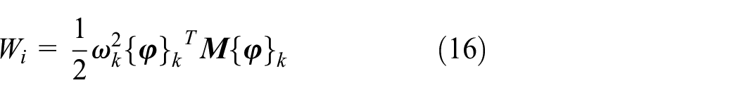
The main propulsion cylinder plays a major axial support role in the main drive system. In order to study the influence of the axial stiffness of the main propulsion cylinder on the dynamic characteristics of the system, the relationship between its stiffness and the overturning and translational vibration of the main beam was extracted as shown in Figure 15.
Relationship between the stiffness of the propulsion cylinder and the RMS value of the main beam vibration. (a) The relationship between propulsion cylinder stiffness and translational vibration RMS value. (b) The relationship between propulsion cylinder stiffness and overturning vibration RMS value. (c)The relationship between propulsion cylinder stiffness and translational vibration amplitude. (d)The relationship between propulsion cylinder stiffness and overturning vibration amplitude.
It can be seen that the angle of the overturning vibration of the main beam and the stiffness of the propulsion cylinder have a significant impact on the lateral overturning vibration of the main beam, while they have almost no effect on the longitudinal overturning vibration of the main beam. When the stiffness of the propulsion cylinder is less than 4e8 N/m, the RMS value and amplitude of the transverse overturning vibration in the front section of the main beam do not change significantly, at the levels of 0.6–0.7 rad/s 2 and 1.8–1.9 rad/s 2 , respectively. When the stiffness of the propulsion cylinder is greater than 4e8 N/m, the RMS value and amplitude of the transverse overturning vibration in the front section of the main beam show a significant downward trend. When the stiffness of the propulsion cylinder increases to 1e9 N/m, the RMS value of its lateral overturning vibration decreases by 59.93% and the amplitude decreases by 57.66%. From the perspective of translational vibration of the main beam, the stiffness of the main propulsion cylinder has the most significant impact on the axial vibration of the main beam, followed by its lateral vibration, and has little effect on its longitudinal vibration. The axial vibration amplitude and RMS value significantly decrease with the increase of its equivalent support stiffness. During the process of increasing its support stiffness from 1e8 to 10E8, the axial vibration amplitude of the main beam decreased by 33.44%, and its axial vibration RMS decreased by 43.60%. The RMS value of lateral vibration shows a slight decrease with the increase of the stiffness of the supporting oil cylinder, which is 2.62% lower than that when the stiffness is 1e8 N/m. The amplitude and RMS value of its longitudinal vibration are not significantly related to the equivalent support stiffness of the main propulsion cylinder. The lateral vibration amplitude shows a significant change with the increase of equivalent support stiffness. When the lateral vibration amplitude of the main beam is below 5e8 N/m, it shows a negative correlation with the equivalent support stiffness of the main propulsion cylinder. When the lateral vibration amplitude is above 5e8 N/m, it shows a positive correlation with the equivalent support stiffness of the main propulsion cylinder.
Sensitivity analysis of radial stiffness of main bearing
In order to study the influence of the radial stiffness of the main bearing on its dynamic characteristics, the relationship between the radial stiffness of the main bearing and the radial translational vibration of the cutterhead and support housing was extracted as shown in Figure 16.

Relationship between main bearing radial stiffness and system acceleration. (a) The relationship between main bearing stiffness and vibration RMS value of cutterhead. (b) The relationship between main bearing stiffness and vibration RMS value of shield. (c)The relationship between main bearing stiffness and vibration amplitude of cutterhead. (d)The relationship between main bearing stiffness and vibration amplitude of shield.
It can be seen that the RMS value of the transverse and longitudinal translational vibration of the cutterhead fluctuates slightly with the increase of the radial stiffness of the main bearing. The RMS value of its lateral translational vibration is in the range of 5.03–5.45 m/s 2 , and the RMS value of its lateral translational vibration is in the range of 4.89–5.30 m/s 2 . The lateral translational vibration amplitude of the cutterhead significantly decreases within the range of 5–7e8 N/m of the main bearing radial stiffness, with a reduction of 25.00%. The amplitude of its longitudinal translational vibration shows a slight overall increase trend during the increase of the radial stiffness of the main bearing, with an increase of 13.66%. The RMS value and amplitude of the lateral and longitudinal translational vibration of the supporting shell significantly increase with the increase of the radial stiffness of the main bearing. The RMS values of its lateral and longitudinal translational vibrations increased by 1 and 0.66 times, respectively, while the amplitude of its lateral and longitudinal translational vibrations increased by 1.72 and 0.56 times, respectively.
Vibration transmission law of TBM main drive system
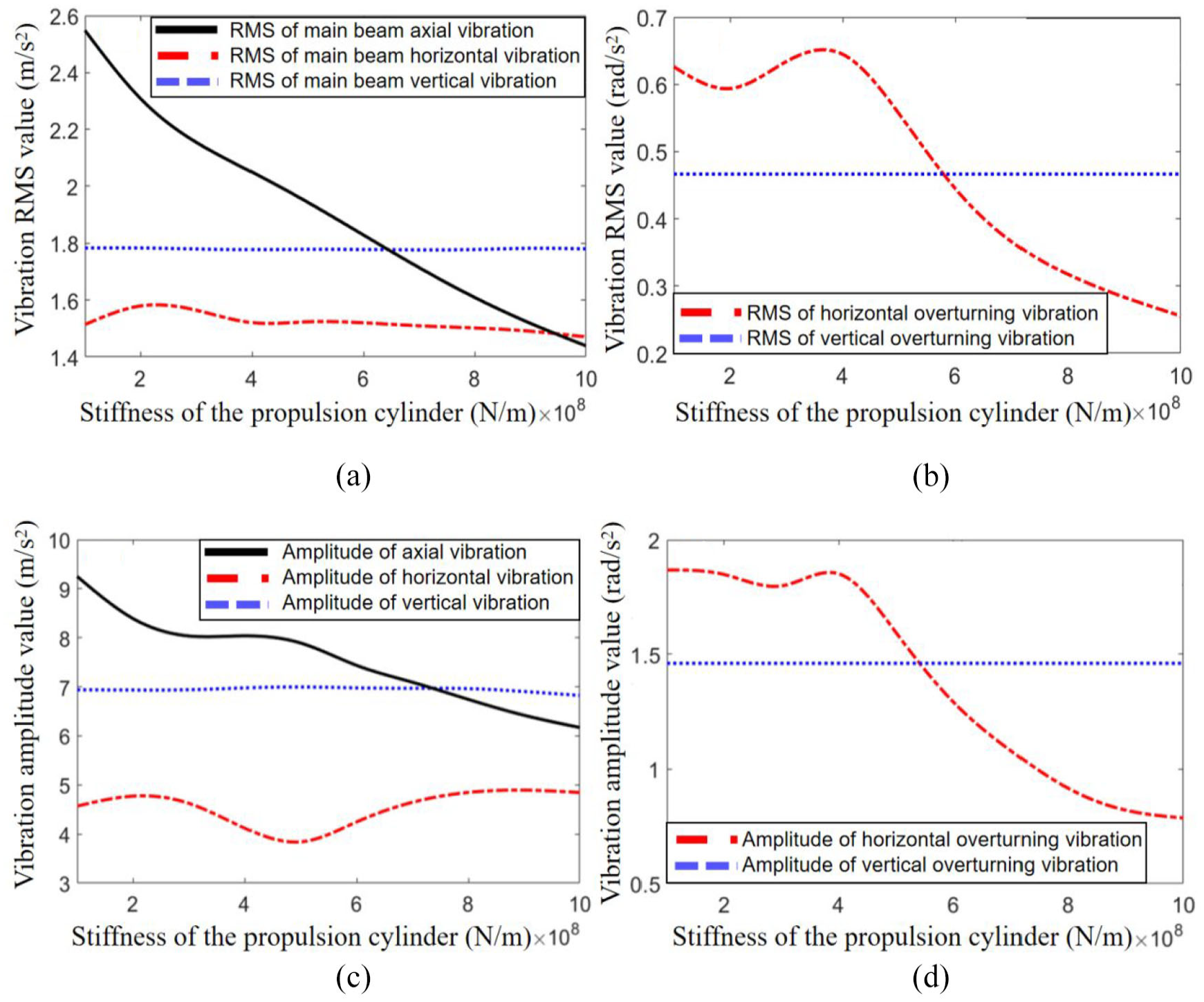
Figure 17 shows the vibration data of acceleration at the position of the cutter head, shield body, main beam and center mass of the gripper shoe. The variation law of the RMS value and amplitude of the vibration acceleration of the system along the main drive driving direction is shown in the Figure 14 and Table 5. It can be seen that the axial translation vibration of the system presents a continuous attenuation trend along the driving direction. The RMS value of the axial translation vibration at the mass center of the shield body is reduced to 59.01% of the cutterhead, and the maximum amplitude is reduced to 55.97% of the cutterhead. The RMS value is reduced to 0.2411 g at the front section of the main beam, which is 35.51% of the cutter head, and the maximum amplitude is reduced to 0.8217 g, which is 44.79% of the cutter head. The horizontal and vertical translation vibration of the system is significantly reduced when the vibration is transmitted to the shield body, the RMS value is reduced to 25.94% and 27.04% of the cutterhead, and the amplitude is reduced to 21.23% and 18.50% of the cutter head. In general, the horizontal and vertical translation vibration first showed a significant decrease to a lower level at the shield body, then increased slightly at the front of the main beam, and finally gradually decreased along the back of the main beam. This shows that the shield body plays a major radial support role for the TBM main drive system.

Vibration transmission law of TBM main drive system. (a) Translation vibration RMS value transmission law of TBM main drive system. (b) Overturning vibration RMS value transmission law of TBM main drive system. (c) Translation vibration amplitude transmission law of TBM main drive system. (d) Overturning vibration amplitude transmission law of TBM main drive system.
Acceleration response statistics.

The horizontal and vertical overturning vibration of the system shows an obvious increasing trend at the shield body. Its RMS value reaches 155.21% and 130.11% of the cutter head, and its amplitude reaches 123.60% and 118.99% of the cutter head. This trend may be due to the small size of the connecting flange between the main beam and the shield body, which is prone to overturning vibration. Figure 18(a)–(c) show the frequency domain diagrams of the displacement vibration of the shield in different directions.

Frequency response of support shell displacement vibration: (a) axial vibration, (b) radial vibration, and (c) overturning vibration.
It can be seen from Figure 18 that the main vibration form of the shield body is the coupled vibration around 15–20 Hz. Radial translation vibration and overturning vibration also show significant peaks at low frequencies (below 1 Hz), which are mainly due to the periodic change with a frequency of 0.093 Hz under the rotation period of the cutter head.
In order to better compare the vibration energy ratio of the system, after normalizing the vibration energy, the statistical value of the vibration energy ratio of each part is shown in Table 6.
Statistical value of vibration energy proportion.

It can be seen from Figure 19 that at the position of the cutter head, the radial vibration, axial vibration, and overturning vibration energy of the system are close. At the shield position, the proportion of radial vibration is significantly reduced, and the proportion of vibration energy is reduced to 7.83% and 9.44%, respectively, and the radial vibration energy only accounts for less than 20% of the total system energy. The proportion of overturning vibration energy increased significantly, and the proportion of its overturning vibration energy reached 30.78% and 17.78%, respectively. When in the position of the main beam, the vibration energy in all directions is in an average condition again. Its horizontal translation vibration energy is the largest, reaching 23.8%. According to the statistical value of the vibration energy ratio in each direction in Table 6, the variation law of the vibration energy ratio is shown in Figure 16.
Law of vibration energy proportion change.
Conclusion
Based on the distributed support of the main drive system and the structure of multi-source input, this paper analyzed the coupling relationship between the degrees of freedom of the system. Considering the nonlinear internal excitation of bearing dynamic stiffness, gear meshing error, tooth side clearance, this paper established a multi DOF coupling dynamic model of the main drive system, including the cutter head, transmission system, support, and propulsion system. The vibration of the main part of the TBM is measured. Based on the measured data, the dynamic model of the main drive system is corrected, and the maximum errors in the calculation of the three-dimensional vibration of the TBM cutterhead, the shield body, and the front section of the main beam are within 18%, 21%, and 22%, respectively.
The analysis shows that the axial acceleration frequency domain response of the cutter head is the vibration of a wide frequency domain bandwidth. At the same time, it shows a larger proportion in the frequency domain of 20–30 Hz and 50–60 Hz. The vibration of the cutter head is mainly reflected in the forced vibration of the system under the external excitation load, which is consistent with the characteristic that the cutter head is in direct contact with the surrounding rock at the front end of the system. For the connection flange between the shield body and the front section of the main beam, the frequency domain response of the axial vibration acceleration is obviously concentrated at 18–20 Hz. The main frequency band is relatively consistent with the measured frequency domain response, which is mainly caused by the excitation of the first three-order natural frequencies of the system under the action of the system’s broadband external excitation load.
The coupled vibration of radial overturning vibration and lateral translation vibration is easy to appear in the actual vibration of the system. The influence of the main mass parameters and stiffness parameters of the system on the various modes of the system is analyzed, and the modal transition points under each dynamic parameter are obtained. By studying the nonlinear variation law of the main components of the system along the main drive tunneling direction, it is found that the overturning vibration of the shield body has a significant “amplification effect,” and its amplitude reaches 123.60% and 118.99% of the cutter head, respectively.
In terms of dynamic modeling research, the coupling relationship between hydraulic and mechanical systems should be considered in the future, which may have an influence on the vibration and load characteristics of the main load-bearing area of the system. At the same time, the clearance and assembly parameters between key components of the TBM main drive system also have an influence on its dynamic behavior. In subsequent research, the dynamic model should be further improved to address this issue. In terms of validating the dynamic model, future research can combine vibration big data to calibrate the dynamic response of the dynamic model under different complex rock conditions, thereby improving the applicability and universality of the dynamic model.
Footnotes
Handling Editor: Sharmili Pandian
Declaration of conflicting interests
The author(s) declared no potential conflicts of interest with respect to the research, authorship, and/or publication of this article.
Funding
The author(s) disclosed receipt of the following financial support for the research, authorship, and/or publication of this article: This work was supported by the National Natural Science Foundation of China (Grant No. 51375001), NSFC-Liaoning United Foundation (Grant No. U1608256), and Natural Science Foundation of Zhejiang Province (Grant No. LTGY23E070001).