
Abstract
The axial vibration in turbine machine has attracted more and more interest. Tilting-pad thrust bearings are widely used in turbine machines to support the axial load. The dynamic properties generated by oil film of the thrust pad have important effects on the axial vibration of the rotor-bearing system. It is necessary to develop the method to test the dynamic characteristics of thrust bearings. A new rig has been developed. The facility allows a complete set of bearing operating parameters to be measured. Parameters measured include oil temperatures, oil-film thickness, and pressure. The static load and dynamic load can be added on the thrust bearing in the vertical direction at the same time. The relative and absolute displacement vibrations of the test experimental bearing with the changes of dynamic force are measured, and the dynamic characteristics of the test bearing are obtained. The experimental results show clearly that the operating conditions influence largely on the pad static and dynamic characteristics.
Introduction
Stability study is usually focused on the lateral vibration of horizontal sets but not on the axial rotor system in general. However, with the turbines rotating at a higher speed and becoming more powerful, the axial vibration has been obtaining more interest from the research communities. As a key component, tilting-pad thrust bearings are widely used in turbine machines to support the axial load. The dynamic properties generated by oil film of the thrust pad play an important role on the axial vibration of rotor-bearing system. Therefore, there is a demand for developing a test method to study the dynamic characteristics of thrust bearings.
Noticeable contributions to the experimental investigations of static behaviors of hydrodynamic lubricated thrust bearings can be found in literature.1–6 Heinrichson and Fuerst 1 performed experimental investigation of the influence of an oil injection pocket on the pressure distribution and oil-film thickness. Measurements of the pressure and oil-film thickness distributions were presented for tilting-pad thrust bearing with surface area of the pad around 100 cm2. Two pads were measured in a laboratory test rig at loads of 1.5–4.0 MPa with velocities up to 33 m/s. Almqvist et al. 2 compared a thermohydrodynamic (THD) model and numerical simulation of hydrodynamic thrust bearings with experiments results. The test rig contained two identical equalizing pivoted pad thrust bearings. The power loss, running temperature, and pressure profiles were measured and presented as functions of load and rotational speed. Glavatskih and colleagues3–5 developed a thrust bearing test rig, which could measure the film temperature and frictional torque. Harika et al. 6 experimentally studied the effect of water contamination on the tilting-pad thrust bearings lubrication. An eight shoes tilting-pad thrust bearing supplied with water-contaminated oil in which the contamination rate reached 10% of water by mass was investigated. Dwyer-Joyce et al. 7 performed an experiment on a full-size polytetrafluoroethylene (PTFE)-faced thrust pad designed for a hydroelectric power station turbine. An ultrasonic method was developed for oil-film measurement and served as a condition monitoring tool. The ultrasonic transducer was mounted on the back face of the thrust pad with a series of calibration procedures. Dadouche et al. 8 analyzed the characteristics of a fixed-geometry thrust bearing in typical operating conditions and gave experimental results to facilitate and validate THD lubrication models. The influence of the applied load, the rotational speed, and the feeding temperature on the thrust bearing performance was presented and discussed. Berger et al. 9 emphasized that the hydrodynamic thrust bearing provided additional stiffness and additional damping to the rotor-bearing system. And axial vibrations of the shaft had to be taken into account in order to completely analyze the coupling between the thrust bearing and the bending vibration of the shaft.
Compared with the theoretical study of the dynamic behavior of thrust bearings, the experimental study of thrust bearing dynamic performance is seldom reported. In this article, the tilting-pad thrust bearing’s characteristics, especially the dynamic properties, are studied experimentally. A new test rig has been developed for the purpose of investigating the static as well as the dynamic performances of tilting-pad thrust bearings. The thrust bearing to be tested is assembled in a suspended bracket with the flexibility of testing various kinds of thrust bearings. Temperature and pressure at various locations on the thrust bearing pads are measured. The hydrodynamic lubrication film stiffness and damping coefficients are obtained by measuring the relative and absolute displacement of the test bearing. The testing results are presented and discussed.
Test program
Experimental investigations of static and dynamic characteristics of tilting-pad thrust bearing are presented for a line-pivoted tilting thrust pads. A new test rig is designed and fabricated. The test rig consists of a driving system, a loading system provided with both static and dynamic loading, a testing rotor-bearing system, a lubricating system, and a data acquisition system. Test parameters include pad temperature, pressure, and vibration of the test bearing. In addition to the static loading test, a test procedure is developed for dynamic loading. The stiffness and damping characteristics of hydrodynamic lubrication film can be obtained with the assistance of computational simulation algorithm.
Experimental apparatus
The structure of the test rig is shown in Figure 1. A steel base is used to support the main test unit. The main shaft is driven by a motor through a flexible coupling with an adjustable speed controller.

Sketch of test rig.
The main shaft aligns vertically, and it is supported by a pair of rolling bearings. A plate, which mates against the test bearing, is mounted on the main shaft. While the shaft rotates, hydrodynamic film is formed between the test bearing and the runner plate. The test bearing is suspending by three groups of wire ropes to isolate structural vibrations. The loading system includes static loading and dynamic loading assemblies. The driving stepper motor drives a ball screw to apply static axial load. A spring located between the static load support and the test bearing is installed in the static loading system to isolate vibration. A load sensor is used to measure the axial static load. An electromagnetic exciter, assembled on a different support to avoid possible interference with static load system, is used to achieve the dynamic axial load. A dynamic load sensor is assembled to the exciter to measure the axial dynamic load. The dynamic characteristics of the thrust bearing will be obtained by measuring the relative displacement between the test thrust bearing and the runner plate, and the absolute displacement between the thrust test bearing and the ground base.
Test parameters and sensors
The performance of the line-supported tilting-pad thrust bearing is experimentally studied. Test parameters are listed in Table 1. The test bearing has three line-supported pads. The inner diameter of the pad is 110 mm, and the outer diameter of the pad is 220 mm. The pad angle is 45°, and the pad pivot angle is 27°. The pad thickness is 28 mm, and the babbitt layer thickness is 1 mm.
Test parameters.

The thrust bearing has been equipped with sensors to provide the data of performance characteristics. In order to determine the temperature distribution over the entire pad surface, an array of nine Pt thermocouples is evenly distributed in the pad. The layout of thermocouples on the pad is shown in Figure 2(a). The distance between active probe surface and pad surface is 3 mm. The measuring accuracy of the temperature is ±0.1 °C.

Distributions of sensors at the back of the pad: (a) thermocouples distribution and (b) pressure sensors distribution.
Six pressure sensors are installed in the pad as shown in Figure 2(b). The pressure distribution is measured by pressure sensors via oil pipes which are connected to these through pressure holes. The N-S pressure sensor is used to measure the oil pressure which is in the range of measurement of 0–5 MPa.
Displacement sensors are used to measure the vibration, and thus dynamic characteristics of the thrust bearing can be analyzed. The arrangement of displacement sensors is shown in Figure 3. Three proximity probes are placed along 120° circumferential direction of test bearing block. We obtain the oil-film thickness by taking three values. The probe is made by China aviation machinery research institute. Its range of measurement is 0–1 mm and resolution is 1 µm. Both the relative and the absolute displacements are measured, and the dynamic characteristics of the thrust bearing are analyzed by solving governing equations discussed in the following section.

Location of displacement sensors.
Three pads are uniformly distributed in the circumferential direction. And holes are drilled at the back of the pads to assemble the thermocouples and pressure pipes.
Dynamic characteristics test method
The dynamic model of thrust bearings is simplified as shown in Figure 4, where M is the equivalent mass of the test thrust bearing, K is the vertical spring stiffness, and C is the vertical damping. Therefore, the dynamic behavior of the thrust pad can be characterized by the stiffness coefficient and the damping coefficient.

The dynamic model of the test thrust bearing.
The test rig is designed as an invert structure. The main shaft only has the degree of freedom (DOF) in rotational direction. The test bearing is excited using the electromagnetic exciter in vertical direction. Dynamic data include the bearing relative position with respect to the shaft, absolute displacement of the bearing, and dynamic load applied by the shaker.
The equation of motion for the bearing mass m in vertical direction can be written as follows

where relative displacement
After substituting these terms into equation (1), it can be rewritten as

Dividing by


In equations (3) and (4), the bearing mass, the excited dynamic load T, relative displacement
The displacement data in time domain is transferred with fast Fourier transform (FFT) to be treated as amplitude-frequency data. The dynamic coefficients are solved in frequency domain.
Results and discussion
Static test performance
Before the formal experiments, we should perform the experiment preheating process. At a constant speed, load 400–1400 N in stages (under each load for 15 min), and start formal experiment after stabilizing temperature and pressure.
The effect of applied load on pad temperature is studied. Figure 5 shows a set of results for oil-film temperature as obtained under different loads. The distributions of the pad temperature in circumferential direction (section A in Figure 2(a)) are presented in Figure 5(a), in which the rotational speed is 915 r/min and the feeding temperature is 20 °C. We can find that the pad temperature increases noticeably with the increase of applied load. The pad temperature also increases with the increase of angle at the same radius.

The distribution of pad temperatures in (a) circumferential and (b) radial directions (915 r/min).
With the same testing condition, the distributions of the pad temperatures in radial direction (section B in Figure 2(a)) are presented in Figure 5(b). Again, the pad temperature increases with the increase of applied load as expected. On the contrary, the pad temperature increases slightly with the increase of radius at the same angle because of the small operating speed and loading.
In Figure 5, we can observe that the effect of increasing the applied load leads to increase in temperature.
The influence of rotational speed on the pad temperature is also studied. The speed tested ranges from 600 to 1200 r/min. The distributions of the pad temperature in circumferential direction (section A in Figure 2(a)) are presented in Figure 6(a), in which the applied load is 1420 N. On varying the rotational speed, it was seen that, in general, the pad temperature increases with increase in speed. The pad temperature also increases with the increase of angle (from inlet to the outlet) at same radius. This effect is more pronounced at higher rotational speed.

The distribution of pad temperatures in (a) circumferential and (b) radial directions (1420 N).
The distributions of the pad temperatures in radial direction are presented in Figure 6(b). The pad temperatures increase noticeably with the increase of the rotational speed (600 to 1200 r/min). The pad temperatures slightly increase with the increase of radius at the same angle.
The effect of rotational speed on hydrodynamic gauge pressure is shown in Figure 7. The variation of hydrodynamic pressure versus rotational speed, with the applied loading of 1420 N, is presented in Figure 7. The oil feeding temperature is 20 °C. The hydrodynamic pressures near the inner and outer radii vary slightly with the rotational speed. It is noticed that the lowest pressure appears at the leading edge and the edge zone near inner radius. Because the pad pivot cannot be drilled to assemble pressure sensor, the maximum pressure peak appears at the test point near the line pivot and toward the outlet direction.

Variation of hydrodynamic pressure at (a) 800, (b) 1000 and (c) 1200 r/min.
The influence of applied load on film pressure was shown in Figure 8. The variation of pressure versus load with a rotational speed of 915 r/min can be seen. In general, the measured film pressure rises with the incensement of applied load. The variation of the film pressure is more pronounced near the pivot as indicated in Figure 8 that the maximum pressure varies from 0.28 to 0.56 MPa when the load increases from 650 to 1310 N.

Variation of hydrodynamic pressure at (a) 650 N, (b) 1080 N, and (c) 1310 N.
Dynamic test performance
The dynamic characteristics of tilting-pad thrust bearing are investigated with this newly designed rig. The test parameters are listed as follows: feeding temperature is 13 °C, rotational speed ranges from 800 to 1400 r/min, dynamic load force is 26.84 N at a frequency of 70 Hz, and static applied load is 410 N.
Experimental results of film thickness have also been obtained by averaging readings from displacement probes. Sensor tips were positioned about 0.5 mm above the pad surface.
The test results show that the film thickness increases when the rotational speed increases, which have agreement with common theoretical analysis. After the displacement data is FFT treated, a FORTRAN program is used to solve equations (3) and (4) to calculate the dynamic characteristics of the test thrust pad. The results of stiffness and damping coefficients of the thrust bearing are shown in Figure 9.

Stiffness coefficients and damping coefficients at 800–1400 r/min.
For a given speed, the increase of speed leads to a significant increase in the gap between the pad and the runner.
The film thickness is compared at 400–1200 r/min in Figure 10. The film thickness decreases noticeably with the increase of the applied load.

Film thickness with the increase of load.
In Figure 11, it can be seen easily that stiffness coefficients increase obviously. But damping coefficients slightly change with the increase of applied load. This observation is consistent with the theoretical findings in general.
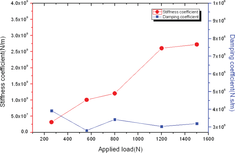
Stiffness coefficients and damping coefficients at 800 r/min.
It can be seen from dynamic characteristic versus exciting frequency in Figure 12 that the influence of exciting frequency on the stiffness coefficient is big. The increase of exciting frequency contributes to adding the value of stiffness coefficient. Damping coefficients slightly change with the increase of exciting frequency in the specified range of frequency.
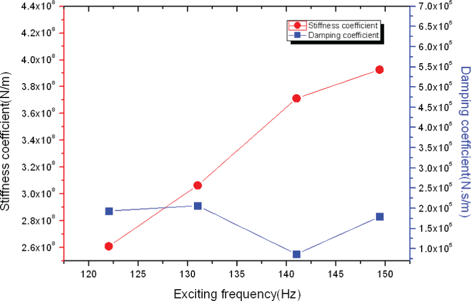
Stiffness coefficients and damping coefficients at 800 N load.
Conclusion
A new thrust bearing test rig has been developed. The measured parameters include temperatures, film thickness, and film pressure. And the dynamic properties of the thrust bearing are experimentally studied.
Based on the test results, some conclusions can be obtained. The dynamic properties could be tested by this test rig. And the variations of thrust bearing’s stiffness and damping coefficients are measured under the test conditions. The experimental data show that the increase of the exciting frequency can increase its stiffness coefficient, but among a specified range, it has little influence on damping coefficients.
Footnotes
Academic Editor: Wen-Hsien Kao
Declaration of conflicting interests
The authors declare that there is no conflict of interest.
Funding
This work is supported from Natural Science Foundation of China (NSFC) project (No.50876057) and Shanghai Key Laboratory of Manufacturing Automation and Robotics.