
Abstract
Industrial robots play a crucial role in intelligent manufacturing production lines. By installing a six-dimensional force sensor at the end of the industrial robot’s wrist, a force/position control method is designed in this paper, which simplifies the teaching complexity of the assembly robot and achieves smooth assembly. Employing an admittance control strategy, the signals of external force/torque received by the robot end from the six-dimensional force sensor are used as inputs, while the position/pose deviation of the robot end serves as output, enabling drag teaching during assembly. The actual peg and hole mating process performed by the industry robot is divided into three stages: hole-searching, chamfer-entering, and inserting. By analyzing the contact force on the peg in each stage, the control parameter matrix for the assembly force/torque to posture is determined. A robot joint variable-solving algorithm is designed to dynamically adjust the motion of each axis of the robot in real-time, realizing compliant control in the presence of contact force/torque during assembly. Taking the example of parts with a peg-in-hole fit tolerance of φ25H7/g6, actual assembly experiments are conducted. The experimental results have verified the effectiveness of the control strategies for industrial robot drag teaching and parts assembly system.
Keywords
Introduction
Assembly operations are a common process in actual industrial production lines. Compared with other production and manufacturing processes, they have high technical requirements and involves positional and force constraints. Assembly operations require high accuracy and strong repeatability. 1 Therefore, substituting manual assembly tasks with industrial robots can significantly enhance productivity and reduce production costs.2,3 With the continuous advancement of intelligent manufacturing, assembly robots are widely utilized in assembly production lines, particularly in heavy-duty assembly industries, due to their fast assembly efficiency, high quality, and enhanced safety during the assembly process.4–6
As the application scope of assembly robots gradually expands, the requirements for robots performing assembly operations are also escalating, making the intelligence of assembly robots an inevitable trend for future development. The development of intelligent assembly robot technology involves multiple technical domains, such as sensor technology, computer vision and image processing technology, and intelligent control technology.7–9 The integration of these technologies is beneficial for reducing the complexity of robot teaching, improving positioning accuracy, and achieving compliant assembly.10,11
The primary challenge for assembly robots is to enhance assembly precision and ensure assembly safety. Since the typical repeatability of industrial robots cannot meet the requirements of high-precision assembly tasks, incorporating visual or force sensing into industrial robot systems is a common approach to address precise and safe assembly. However, visual assembly by robots imposes high demands on lighting conditions, image quality, and incurs high costs. In high-precision assembly tasks, leveraging force control technology, robot assembly systems with force control strategy can compensate for robot positioning errors, thereby meeting high precision requirements, and enabling compliant assembly.
The common force compliance control methods for robots include passive compliance and active compliance. Passive compliance requires the installation of customized passive energy storage mechanisms at the end of the robot to achieve buffering of docking contact force/torque. 12 In the realm of passive compliance control, a prominent example is the Remote Center Compliance (RCC) device, developed by Draper Laboratory under Whitney’s leadership at MIT. This micro-offset compliance mechanism is designed for assembly operations, allowing compliant motion relative to any specified center of compliance. 13 However, once the compliance center of the RCC device is established, it becomes challenging to adjust. Traditional RCC relies on its mechanical structure for compliance, representing a passive compliant control method. However, for assembly robots, purely passive compliance lacks flexibility and cannot guarantee the magnitude of contact force.
Active compliance control is achieved by establishing an active control mechanism to achieve compliance performance. Usually, force sensors need to establish force feedback and introduce control models such as impedance control and force/position hybrid control to achieve real-time control of end contact force/torque.14,15 The active compliance control scheme is not constrained by the assembly scene and assembly objects, and has higher control accuracy, so it has received increasing attention from researchers.
Lopes and Almeida 16 proposed an automatic impedance control device (robotic controlled impedance device, RCID), combining RCID with a six-degree-of-freedom industrial robot to achieve compliant peg-in-hole assembly operations. Based on analyzing the contact force model of peg-in-hole assembly, Zhang et al. 17 used fuzzy impedance control method to achieve robot flexible assembly for dual peg-in-hole. Yan et al. 18 conducted research on the assembly problem of randomly inclined bases, and based on support vector machine (SVM), classified the contact state model of peg-in-hole assembly, which can achieve the assembly of any randomly inclined base from −30° to 30°. A hole search algorithm based on a combination of reinforcement learning and force position hybrid controller is proposed, which completed the hole search task with fewer steps. In response to the problem of weak robustness of fixed impedance parameters, reinforcement learning was used to adjust impedance parameters in real-time and successfully complete the socket task.
Based on the inspiration that humans can easily complete the process of peg-in-hole assembly, some studies tend to imitate and learn the trajectory of the socket from human assembly, so that robots can replicate this trajectory. Dragging and teaching to pull the robotic arm is a very direct way of imitation. 19 The main process of robot assembly operation under force control mode is as follows: Firstly, the operator collects teaching points for the robot’s operation process by dragging through the teaching function. Then, during the assembly operation, adjustments are made based on the position and posture of the robot’s end effector controlled by contact force to complete the assembly task. 20 Traditional teaching methods for obtaining insertion hole teaching points involve controlling the robot’s movement with a teaching pendant. Due to the small gap between the peg and the hole, it is difficult to insert the peg into the hole, resulting in high operational difficulty. By utilizing the drag teaching function, the robot end effector smoothly inserts into the hole based on contact force, reducing the difficulty of teaching operations, ensuring operational safety, and reflecting the characteristics of human-robot interaction.
This paper simplifies the industrial robot system hardware by only installing a six-dimensional force sensor on the robot wrist, thus extending the functionality of drag teaching and compliant assembly for ordinary industrial robots. Firstly, a force control strategy for drag teaching is designed and implemented. When the gap between the peg and the hole is too small for teaching pendant teaching, convenient manual drag teaching is provided, offering a reasonable and effective assembly path for robot operations. Subsequently, the control parameter matrix for assembly contact force/torque to pose is determined based on different assembly stages. Joint variable solving algorithms and force/position hybrid control algorithms are designed to dynamically adjust the motion of each robot axis in real time during the assembly process, achieving intelligent assembly.
Composition of the assembly robot system
The assembly robot system consists primarily of industrial robots, six-axis force sensors, data acquisition cards, I/O modules, robot controllers, host computers (PCs), and teach pendants, as shown in Figure 1. The industrial robot selected the ER20-C10 six-degree-of-freedom robot (EFORT Intelligent Equipment Co., Ltd), equipped with a controller from KEBA company. Based on the KeMotion system platform, the controller managed hardware devices such as I/O modules, robot motor drives, data acquisition cards, and communication interfaces. A BIOFORCEN six-dimensional force sensor (Anhui Eli Intelligence Technology Co., Ltd.) is installed between the robot wrist and pneumatic gripper to feedback contact force/torque data for the robot drag teaching and compliant assembly.

Assembly robot system.
The assembly objects of the industrial robot in this paper are typical parts of an agricultural machinery gearbox, namely planetary peg and cross-shaped part with chamfered hole, which require peg-in-hole assembly. The assembled parts are shown in Figure 2.

The sectional view of peg-in-hole assembly.
The cross-shaped part is mounted in the gearbox housing by first passing a long planetary peg through the chamfered hole in the cross, then inserting two short planetary pegs vertically to the long planetary peg, and finally encapsulating them together with other parts into the gearbox housing. The robot peg-in-hole assembly operation targets the installation step of inserting the long planetary peg. The peg-in-hole fit tolerance of the parts is φ25H7/g6, belonging to a clearance fit.
Analysis and modeling of force-position relationship in peg-in-hole assembly
During the assembly process, it needs to analyze the contact force when inserting the peg into the workpiece hole and control the robot to adjust its position and posture. Peg-in-hole assembly is a multidimensional force-controlled process. As the contact points change during the assembly process, the force analysis of the peg is a complex and dynamic process. According to the actual situation of the parts shown in Figure 2, the peg-in-hole assembly process is divided into the hole-searching stage, the hole chamfer-entering stage, and the inserting stage.
Hole-searching stage
In the hole-searching stage, the robot adjusts the gripper position and posture to enable the peg to find and reach the correct insertion position. During this process, when the peg touches the workpiece surface, contact force occurs between them, and once the contact force disappears, it indicates that the peg is aligned with the insertion hole. Since the robot’s motion speed is slow, the influence of the acceleration on the measurement of the six-dimensional force sensor can be ignored, the peg-in-hole assembly process can be regarded as a quasi-static equilibrium process. The force analysis of the peg in the hole-searching stage is shown in Figure 3.

Force analysis of hole-searching stage.
Because the six-dimensional force sensor, gripper, and peg workpiece are coaxially mounted, the center of the circular cross-section of the peg workpiece at the contact surface is defined as the coordinate origin “o,” with the insertion direction as the z-axis and the hole surface as the x-y plane. Since there is a certain distance between the contact force action point N of the peg workpiece and the central axis of the six-dimensional force sensor, that is, there is a force arm L, the torque ΔMx and ΔMy are calculated by the following formulas, respectively.


Where, L is the force arm, α is the angle between the force arm L and the x-axis, ΔMx and ΔMy are the torque around the x or y axis, respectively, and ΔFz is the force in the z-axis direction.
Define Δx as the position offset in the x-axis direction, and Δy as the position offset in the y-axis direction. The expressions can be written as follows based on equations (1) and (2).


Thus, by continuously collecting the updated force and torque between the peg and the hole during the system cycle, the position offset in the x and y directions can be obtained to incrementally adjust the robot gripper position. When ΔFz is zero, the insertion hole position is determined, and no further adjustment is needed. At this point, the peg begins to move into the hole, entering the chamfer of the hole.
Hole chamfer-entering stage
Upon entering the chamfer area of the hole, the analysis of the contact force between the inserted peg and the hole wall is illustrated in Figure 4. The definition of the coordinate system is the same as Figure 3.

Force analysis of chamfer-entering stage.
In Figure 4, N represents the contact point between the peg and the chamfer, with the angle between the chamfer and the horizontal plane denoted as φ, the angle between the peg and the chamfer plane denoted as θ, and the pressure ΔFn exerted by the chamfer on the peg perpendicular to the chamfer surface. Its force components in the vertical and horizontal directions, ΔF1 and ΔF2, are calculated as shown below.


The value of ΔF1 is equal to the z-direction force detected by the six-dimensional force sensor installed on the robot’s gripper, with opposite directions, and can be written as follow.

In the right view of Figure 4 (the peg top view), ΔF2 is at the edge of the peg and points toward the center. The angle between the x-axis and ΔF2 is denoted as ω, with force components ΔFx and ΔFy decomposed in the x and y-axis directions, respectively:


The relationship between ΔFx, ΔFy, and ΔFz during the process of the peg entering the chamfered area of the hole can be derived from equations (5) to (9):

After measuring ΔFx, ΔFy, and ΔFz using the six-dimensional force sensor, θ is calculated using equation (10). As indicated in Figure 4, when adjusting θ to be equal to φ, the bottom surface of the peg is parallel to the hole plane. Upon detecting ΔFz equal to 0, it indicates that the peg workpiece has successfully passed through the chamfering area. At this point, the adjustment of the robot’s position in the x and y directions is completed.
Inserting stage
During the stage of inserting the peg into the hole, there is friction between the peg and the hole, necessitating slight rotational maneuvers at the robot’s end effector to fine-tune the gap between the workpiece peg and the hole, thus avoiding workpiece damage. The rotational motion at the robot’s end effector is determined based on the ΔFx and ΔFy detected by the six-dimensional force sensor. When both ΔFx and ΔFy are less than the reasonable contact force, the robot’s wrist stops rotating, allowing downward insertion. If the contact force exceeds the reasonable limit but is less than the maximum allowable force, the insertion action stops, requiring position adjustments in the x and y directions. The adjustment method involves adjusting the position increment Δy in the y direction when |ΔFx| < |ΔFy| and adjusting the position increment Δx in the x direction when |ΔFx| > |ΔFy|. This adjustment process continues until the inserting depth is reached.
Robot joint variable solution algorithm
As assembly operations occur in the operational space, the given desired poses and forces, force/torque information measured by the six-dimensional force sensor at the end effector, and position adjustments calculated during assembly based on contact force/moment are all variables in Cartesian space. However, servo controllers require joint-axis rotation angles in joint space. Therefore, based on robot kinematics, the position and orientation adjustment matrices for the TCP (Tool Center Point) within the robot’s end effector coordinate system, combined with the measured force/torque information, are computed to derive the robot’s joint variables.
Robot position adjustment matrix solution
For a six-degree-of-freedom robot, the homogeneous transformation matrix 0

The components
Based on the ΔFx, ΔFy, ΔFz detected by the six-dimensional force sensor, the offset increments

Robot orientation adjustment matrix solution
Since rotations are relative to a fixed coordinate system, the orientation is calculated using RPY angles, as shown in equation (13). Assuming the current rotation angles of the robot TCP point around the x, y, and z axes of the tool coordinate system are γ, β, α, and make

Comparing the orientation matrix
If

Where,
Based on the Mx, My, Mz detected by the six-dimensional force sensor, the offset rotation angles

By combining

Using the robot’s inverse kinematics function in the KeMotion system, the joint motion angle adjustments for each axis of the robot are derived based on the homogeneous matrix 0
Assembly robot force/position control method
Drag teaching control strategy
When using industrial robots for assembly tasks, it is necessary to specify key path points for the robot during the assembly process. Particularly when obtaining insertion hole teaching points, the traditional teaching method utilizes a teach pendant to control robot movement. However, due to the small gap between the peg and the hole, it is difficult to give the teaching point during the period of inserting the peg into the hole, resulting in extremely high operational difficulty by using the teach pendant. Therefore, a drag teaching function has been developed. By utilizing drag teaching functionality, the robot end effector performs hole insertion teaching based on contact force, reducing the difficulty of teaching operations.
The drag teaching control diagram is shown in Figure 5. F0 represents the desired force, Fa represents the actual measured drag force from the six-dimensional force sensor during the teaching process, and Fg represents the tool gravity compensation value.

Drag teaching control algorithm diagram.
Based on the force deviation ΔF during the dragging process, the position and orientation deviations ΔX are calculated using an admittance control algorithm as shown in equation (17), and the joint variable solving algorithm is used to calculate the robot’s joint angle offsets. The robot’s motors track this position deviation to achieve drag teaching.

In the equation (17),
Force-position hybrid control for peg-in-hole assembly
After drag teaching, the industrial robot is controlled using force-position hybrid control algorithms for peg-in-hole assembly operations. Compared to traditional non-force-controlled industrial robots, this approach not only improves the precision of peg-in-hole assembly operations but also enables smooth assembly. Based on the position control algorithm for robot motors, a force-position hybrid control strategy is designed, as shown in Figure 6.

Force-position hybrid assembly control strategy diagram.
Initially, during the motion of the robot’s gripper in grasping the peg assembly position, only position control is applied. Subsequently, during the peg-in-hole assembly process, including the hole-searching stage, the chamfer-entering stage, and the inserting stage, the gripper pose is adjusted through admittance control strategy to form a force-position hybrid control. The variable S in the Figure 6 (taking values of 1 or 0) represents the control signal for invoking the force control module. When S = 1, the robot system operates in force-position hybrid control mode, whereas S = 0 indicates position control mode. X0 is the desired pose preset by the drag teaching. q0 is the output of six-axis joint angles of the robot calculated by the designed joint variable solving algorithm as mentioned in Section “Analysis and modeling of force-position relationship in peg-in-hole assembly.”F0 is the desired force/torque, and Fr is the actual force/torque detected by the six-dimensional force sensor on-site after filtering. ΔF
During the assembly process, an additional force controller is incorporated and controller coefficients are designed based on force analysis at different stages. As the assembly process progresses, the contact force/torque between the peg and the hole are collected to dynamically adjust the robot assembly position. This ensures successful peg-in-hole assembly and enhances safety during assembly operations. When contact force/torque is eliminated, position accuracy is maintained by the internal servo controller’s position control algorithm.
As analyzed in Section “Analysis and modeling of force-position relationship in peg-in-hole assembly,” in the three stages of peg-in-hole assembly (i.e. hole-searching, hole chamfer-entering and inserting), the positional deviation of the peg is related not only to ΔFx, ΔFy, and ΔFz but also to

Where,
Then the admittance control algorithm during assembly process is written as equation (20), and the joint variable solving algorithm is used to calculate the robot’s joint angle offsets Δq by

Force-position hybrid control experimental validation and analysis
Prototype system
The force-controlled robot test platform is shown in Figure 7. A six-axis industrial robot is equipped with a six-dimensional force sensor at the wrist via a connecting flange, and a three-finger pneumatic gripper is attached at the end of the sensor. The experiment utilized typical parts from agricultural machinery transmissions: a planetary peg and a cross-shaped parts with chamfered holes, to conduct practical assembly operations.
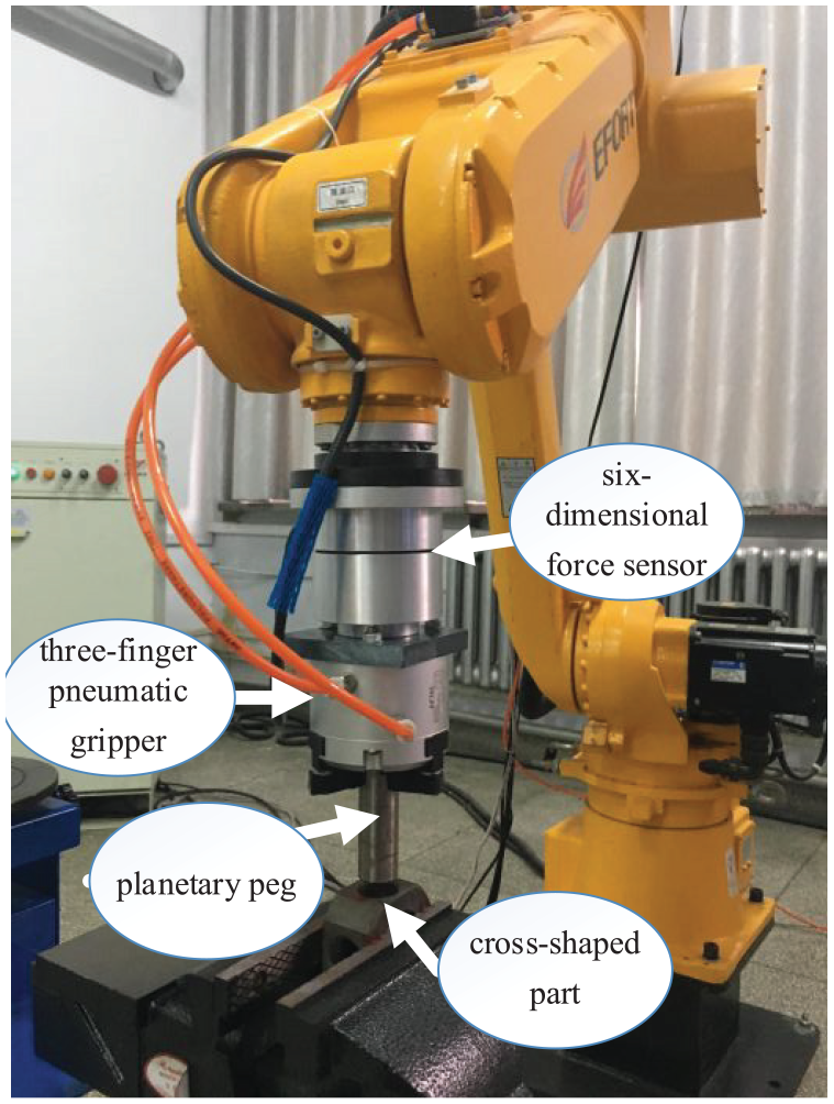
Test platform.
Vertical direction peg-in-hole assembly experiment and analysis
The peg-in-hole assembly process is depicted in Figure 8. The robot’s end effector, a pneumatic gripper, holds the workpiece and moves to the pre-assembly position, as shown at the first moment in Figure 8. Moments 2–4 in Figure 8 represent the hole-searching phase during the assembly process. Moment 5 in Figure 8 corresponds to the hole chamfer-entering stage, and moment 6 to the inserting stage.

The process of hole-searching and peg-inserting in assembly.
During the vertical search and insertion process, significant changes occur primarily in the force/torque

Synchronous variation curves of torque My and position in the x-axis direction: (a) . and (b) position in the x-axis direction.

Synchronous variation curves of torque Mx and position in the y-axis direction: (a)
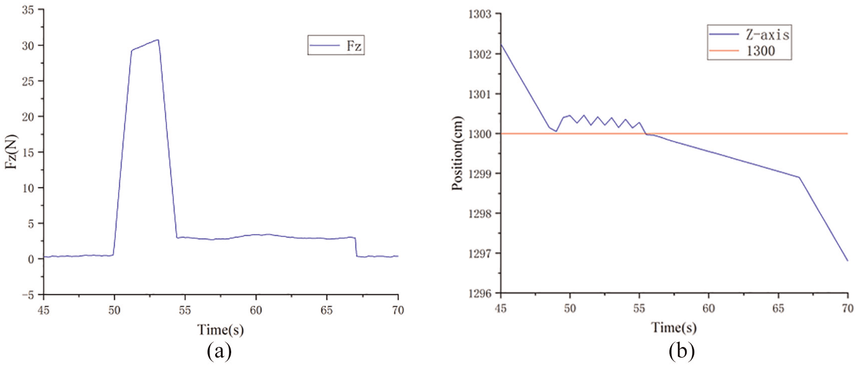
Synchronous variation curves of force Fz and position in the z-axis direction: (a) . and (b) position in the z-axis direction.
Discussion
Based on the assembly site photos shown in Figure 8 and the force analysis, as well as the changes in the robot end position shown in Figures 9 to 11, the characteristics of the assembly robot are analyzed and discussed in detail as follows:
(1) In the first 45 s, the robot’s pneumatic gripper holds the planetary peg and moves to the pre-assembly position, corresponding to the first moment in Figure 8.
(2) From 45 to 60 s, the robot is in the hole-searching phase of the assembly operation, corresponding to moments 2–4 in Figure 8. During this period, position compensations made by the robot’s end effector can be observed. The force/torque curves and the varying position of the robot indicate that during this period, an increase in
(3) From 60 to 67 s, the robot completes the hole-searching phase and enters the hole chamfer area, corresponding to moment 5 in Figure 8. During this short period, the force control system adjusts the position of the planetary peg and the adjusted offset is relatively small. After the peg moves through the hole chamfer area, the system fine-tunes the position of the workpiece peg during the inserting stage, as shown in moment 6 of Figure 8, until the peg-in-hole assembly is completed.
(4) After 67 s, observation of position changes and force/torque in various directions reveals that the contact forces/torques on the robot’s end-effector workpiece are essentially zero, and the peg moves in the negative direction of the z-axis at a stable speed. By this time, the adjustments to the position/orientation deviations between the workpiece peg and the chamfered hole have been completed, and the workpiece peg is smoothly inserted into the hole.
Thus, the force-controlled robot system with the force-position hybrid control strategy meets the assembly precision requirements of φ25H7/g6 clearance fit. According to the tolerance chart, the position accuracy of the force-controlled assembly robot system reaches ±3.5 μm.
Oblique direction peg-in-hole assembly experiment
To further validate the accuracy and versatility of the force-position hybrid control strategy, besides vertical direction peg-in-hole assembly operations, experiments were also conducted in an oblique direction, speeding up the assembly process.
Similar to the vertical assembly operations, the initial steps involve using drag teaching to acquire teaching points and write command programs. However, since the planetary peg is positioned obliquely, control over its position and orientation based on contact forces differs from that in the vertical direction.
Due to the alignment of the planetary peg with the six-dimensional force sensor, even in oblique directions, the peg contact force aligns with the direction of force/torque collected by the sensor. However, due to the angular deviation between the workpiece hole plane and the horizontal plane, a new coordinate system x′, y′, z′ is established. The angles between the x′, y′, z′ axes and the original robot Cartesian coordinate system’s x, y, z axes are illustrated in Figure 12. α represents the angle between the x′-axis and the x-axis, while β denotes the angle between the y′-axis and the y-axis.

Transformation of frames: (a) xoz plane and (b) yoz plane.
Thus, position offset Δx′, Δy′, and Δz′ are calculated by Δx, Δy, Δz, and the angle. During the hole-searching phase, the force control system compensates the robot’s position along the x′ and y′ axes based on the force/torque detected by the six-dimension sensor. During the chamfer-entering and hole-inserting phases, the system adjusts the position and orientation of the planetary peg held by the robot’s end effector.
The force/torque variation curves during the oblique direction peg-in-hole assembly experiment are shown in Figure 13.

The varying curve of force/torque.
From the force/torque variation curves, it can be seen that during the first 3 s of the assembly process, the workpiece peg experiences significant torque fluctuations in the x′ and y′ directions, indicating the hole-searching phase. Force analysis determines the positional displacements of the workpiece peg along the y′ and x′ axes respectively based on Mx and My. Then, during the chamfer-entering and hole-inserting phases, Mx and My values are used to fine-tune the angle of insertion of the workpiece peg into the hole. Ultimately, through adjustments made by the force control system to the robot’s position, the torque Mx and My gradually return to their initial states, and the workpiece peg is successfully inserted into the hole. Six seconds later, the robot completes the oblique direction peg-in-hole assembly task for a φ25H7/g6 fit.
Conclusions
With the advancement of industrial robot technology, intelligent robotics is the inevitable trend. In order to better serve practical industrial assembly operations, higher requirements for assembly robots, such as flexibility, safety, and human-robot collaboration, have been proposed. This paper focuses on the requirements of robotic peg-in-hole assembly operations and completes the development of a robot force control system. The force control system is based on admittance control. Combining with robot kinematic modeling and contact force analysis, it utilizes the information of force/torque collected by the six-dimensional force sensor at the robot end effector as input and the position and pose offset of the robot end effector as output, realizing the robot’s drag teaching control algorithm. Additionally, the system divides the assembly process into stages including hole-searching, chamfer-entering, and hole-inserting. The force exerted on the peg in each stage is analyzed to determine the parameter matrix expression of admittance control. This achieves the goal of adjusting the position and orientation of the peg during the assembly process, realizing the force-position hybrid control algorithm for the peg-in-hole robotic assembly. Assembly tests were conducted using parts with peg-in-hole fitting of φ25H7/g6 as an example. Through practical peg-in-hole assembly operation tests and analysis of test data, it was confirmed that the force control robot system could complete the assembly operation of parts with peg-in-hole fitting of φ25H7/g6, achieving the expected results.
Footnotes
Handling Editor: Sharmili Pandian
Declaration of conflicting interests
The author(s) declared no potential conflicts of interest with respect to the research, authorship, and/or publication of this article.
Funding
The author(s) disclosed receipt of the following financial support for the research, authorship, and/or publication of this article: This work was supported by the Project of Science and Technology of Henan Province (242102220116).