
Abstract
In this work, an effective and practical robot collision detection algorithm is proposed, with the aim of addressing the safety problem of industrial robot force/position hybrid control application conditions. First, a robot force/position hybrid control collision detection scheme was designed, and a collision detection model based on dynamics was established. Then, given the problem of large joint friction force identification error caused by the discontinuous joint speed of the robot force control, the continuous friction model was used to identify and address the joint friction problem through the least square method. Finally, experiments were carried out on a light industrial manipulator. According to the different collision directions of the robots during the experiment, a collision detection method was proposed to monitor the torque changes of the position control joints and the force control joints. Experimental results prove that the continuous friction model is more accurate and effective for joint friction compensation than other methods. The proposed method can achieve effective collision detection with force and position control direction thresholds of 8 and 4 N·m, respectively. The practicability and simplicity of the algorithm that can streamline the process of robot collision detection, the simplified model of the collision detection process only detects the torque change in the position control direction, which has a certain engineering reference value.
Introduction
The application of robots in industrial production, service, medical treatment, and other fields is increasing. The method of closing the working space of robots to achieve human-robot isolation and ensure human-robot safety has not met the new requirements of man-robot inclusive technology. 1 According to the application environment and functional safety requirements of industrial robots, collision detection in the coexistence environment of humans and robots is a basic subject to ensure human-robot interaction and the safety of the equipment itself.
According to the behavior occurrence process of human-robot physical interaction, Haddadin et al. 2 proposed to divide the behavior occurrence process of human-computer physical interaction into seven steps: pre-collision, collision detection, separation, recognition, classification, response, and post-collision processing. Among them, collision detection aims to complete the perception of human-robot interaction information under uncertain factors, minimizing accidental collision damage and maximizing the efficiency of autonomous interaction. 3 For how to better detect whether a robot has a collision, many researches have been carried out on the safety of robots. Buondonno and Luca 4 installed a force/torque sensor at the end of an industrial robot to achieve accurate collision detection between the robot and the external environment, but the sensor is relatively expensive and can only detect collisions at the end of the robot. To detect collisions at any part of the robot, KUKA’s LWR series robots etc. 5 install a torque sensor on each joint, which can achieve better collision detection, but the price is still expensive. To save costs, many scholars have carried out research on sensorless collision detection of robots, which can be roughly divided into model-free and model-based methods. Sharkawy et al.6,7 proposed building a multi-layer neural network based on the Levenberg-Marquardt algorithm to improve the human-robot collision detection capability without the prior knowledge of the dynamics model. Compared with other training methods, it can complete the setting and convergence of larger values with fewer iterations and shorter time. Makarov et al.8,9 decomposed the residual vector into factors related to external torque, model unknowns, and friction, and used an adaptive algorithm to separate the impact of each uncertain item on collision perception, and then set a dynamic threshold to match the best collision detection. Indri et al.10,11 proposed a method for detecting transient changes in current and joint position signals without a dynamic model. The method based on the non-dynamic model has the disadvantages of low sensitivity and system dependence. It cannot be observed for non-violent external collisions and is related to the control characteristics of the system. And another better way is collision detection based on dynamic model. Flacco and De Luca12,13 designed the system residual estimation and identification method to indirectly estimate the observed joint torque, avoiding the use of additional sensors and high-order differential noise. Zhang et al. 14 analyzes the characteristics of the external torque of the robot, establishes a time series model of the external torque, predicts the external torque and generates a dynamic threshold, which has a good effect in eliminating the difference in the sensitivity of collision detection in different directions. Baradaranbirjandi et al.15,16 are combined with the existing robot dynamics model to make a preliminary estimate of the joint speed and acceleration of the tandem chain robot and introduced a new regression-based observer method to significantly improve the accuracy and sensitivity of collision detection. Park et al. 17 combined with the robot dynamics model and momentum observer, using artificial intelligence methods to achieve a wide range of hard and soft collisions of the robot. Based on the robot dynamics model, Li et al. 18 designed a convolutional torque observer, which realizes robot collision detection by observing the deviation between the joint output torque and the dynamic estimated torque in real-time. The reliability of the model-based method depends on the accuracy of the dynamic parameters. However, the dynamic parameters are usually unknown. Effective identification of the dynamic parameters is needed to better realize the collision detection of the robot.
The joint motion of the robot is realized by a deceleration mechanism, and the uncertainty of joint friction is strong. The identification and compensation of joint friction are still in the research stage. Kermani et al. 19 reported that the joint friction of industrial robots is the most important source of errors in their dynamics model. Chen 20 used a simple damping-Coulomb model to solve the problem of joint friction in robot collision detection. Gan et al. 21 used the Coulomb-viscous friction model to identify joint friction and tracked the residual of the collision torque through a dynamic threshold to achieve collision detection. Zhang et al. 22 proposed an improved Coulomb-viscous friction force model, which overcomes the problem of the inaccurate description of the actual friction force by the classic friction force model. To realize the goal of robot collision detection, Sun 23 proposed the four parameters of the Stribeck friction model, which are identified according to the genetic algorithm. Li et al. 24 used the static LuGre model to address the problem of joint friction and designed a convolutional moment observer to realize the effective collision detection of the robot. He 25 proposed to achieve friction modeling and compensation via radial basis neural network for improving the friction modeling method affected by non-linear factors, such as discontinuity during commutation and modeling error. Experiments were carried out on joint 1, and the tracking effect was good. Liu et al. 26 proposed a new joint friction model that can accurately simulate actual friction when the direction of motion changes suddenly. Makkar et al. 27 proposed a continuously differentiable friction model that can describe friction characteristics, including Coulomb friction, static friction, Stribeck phenomenon, hysteresis, etc. The validity of the model is verified by simulation. Lee and Song 28 designed a direct observer to measure the method of joint friction, but the observed joint friction does not exclude the interference of other dynamic parameter deviations. Khan 29 focused on a detailed review and analysis of friction factors.
The abovementioned studies use various methods to identify and address the joint friction problem, which overcomes the difficulties of identifying robot dynamic parameters to a certain extent. However, the verification of the robot collision detection algorithm is mostly conducted in a scenario involving robot-free working spaces. In actual cases, the robot operation process generally involves the constraint control of force and position. When the robot is under the force control constraint, some joints often have non-linear factors, such as continuous speed commutation, sudden change, etc., which make the modeling of joint friction more complicated. The collision detection effect of the dynamic model is not good. Thus, the current paper proposes a robot force/position hybrid collision detection method based on a dynamic model. According to the collision detection requirements of the robot force/position control application, a dynamics-based collision detection model is established, and the continuous friction model is used to identify and address the joint friction problem. Then, a collision detection method is proposed to monitor the respective torque changes of the position control joint and the force control joint. In order to improve the practicability and simplicity of the algorithm, the collision detection model is simplified to only detect the torque changes of the position control joints. Finally, a light industrial manipulator is used as an experimental platform to verify the practicability and simplicity of the proposed algorithm.
Collision detection scheme for hybrid robot force/position control applications
Collision detection scheme
To realize the robot safety force/position hybrid control, a robot collision detection scheme must be established based on several factors, such as the robot’s motion state, dynamic model, force sensor data, etc. The detailed block diagram of the established control scheme is shown in Figure 1. As can be seen, the control scheme is divided into three control processes: position control process, force control process, and collision detection process. The specific procedures of the timing controller 1 and the timing controller 2 composed of timers are as follows:
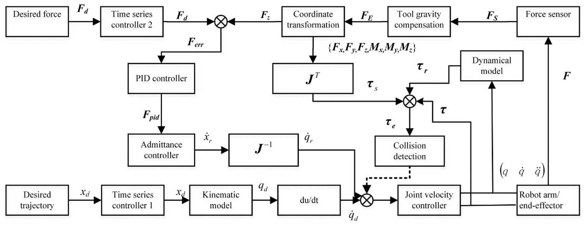
Application of the collision detection strategy to force/position hybrid control.
Position control process
The time function of the motion is planned according to the robot trajectory in order to obtain the desired control position of the robot end. The timing controller 1 is used to divide the robot motion state into three time series, namely, the robot end and the force control object that are not in contact with the
Force control process
Here, the control force output is set according to the requirements of the robot force/position hybrid control application, in order to obtain the desired control force output from the robot end. Then, the timing controller 2 is used to complete the desired control force

Collision detection process
To ensure the safety of the robot terminal force/position hybrid control process, when the robot is in the force/position control phase, the end force {Fx, Fy, Fz, Mx, My, Mz} is collected after calibration according to the sensor, which is then converted by the Jacobian matrix. We set the post-compensation to each joint as
Collision detection method
For a multi-joint series industrial robot with n degrees-of-freedom, we define the motor torque constant


Assuming that the robot arm joints are completely rigid joints when the robot accidentally collides with the environment during the movement, an external force will be applied to the robot. The external force

When the robot performs force/position control, according to the principle of force interaction, an external force

According to the above collision situation, we use the Newton Euler method or Lagrangian method to establish the robot’s rigid body dynamics equation, as shown in equation (7) below.
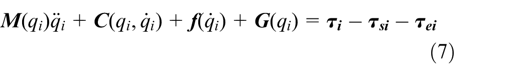
In equation (7),
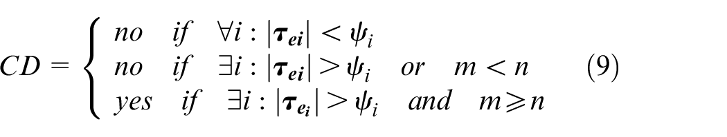
If the robot collides unexpectedly during the force/position control process, the most direct method is to detect the collision torque. The direction of collision detection is shown in equation (9). We refer to collision detection as CD, set the threshold to
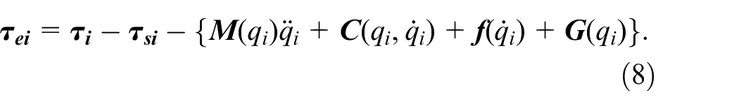
In equation (8),

In the equation,
Identification of the parameters of the continuous friction model
Establishment of the continuous friction model
The mainstream friction models in current robot dynamics parameters include the Coulomb-viscous friction model and the LuGre model, to name a few.28,32 However, there is no suitable model that can accurately describe the friction process in industrial robots. Considering that robot joints generally include motors, harmonic reducers, and output linkages, it is not appropriate to use simple viscous damping to characterize robot joint friction. In the application of robot force/position hybrid control, the joint speed changes frequently, but the existing friction model cannot be modeled well. Makkar 27 proposed a continuously differentiable friction model that can describe friction characteristics, including Coulomb friction, static friction, Stribeck phenomenon, and hysteresis. Given the influence of nonlinear factors, such as slow joint speed and discontinuity during commutation when the robot uses force/position hybrid control applications, joint friction modeling will ignore the problem of friction mutations when the speed crosses 0. Moreover, it can introduce a continuous differentiable friction model for friction identification. The friction force is expressed in equation (11) below 27 :
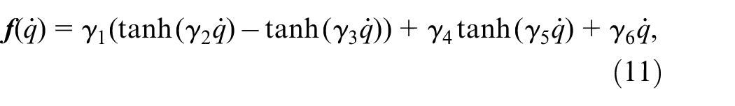
where
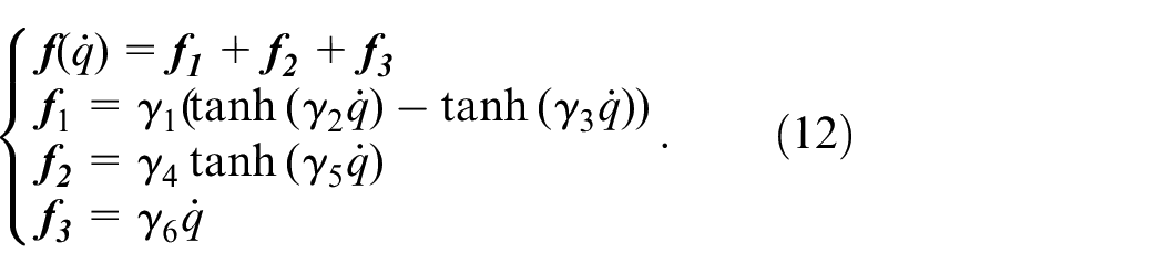
Taking
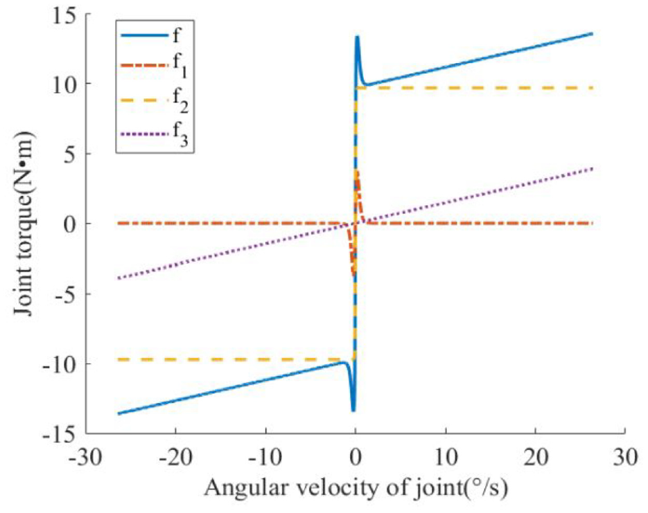
Continuous friction model.
Parameter identification of the continuous friction model
To obtain the frictional force parameters, every single joint of the robot is controlled to move at different speeds, and the different speed values of the joints are extracted to identify the frictional force of the single-link joints. Considering the influence of robot model deviation, connecting rod gravity, and kinematic inertia, among others, on joint friction measurement, we control a certain joint of the robot to perform n times of different speeds in forward and reverse trapezoidal speed planning movements in the motion range

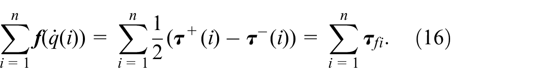
Further, we intercept the uniform velocity part of the joints; respectively collect n sets of joint moments, joint angles, and joint speeds; and establish the equations as follows:
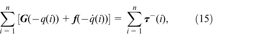
where
We put forward each item in equation (16) separately, as shown below:
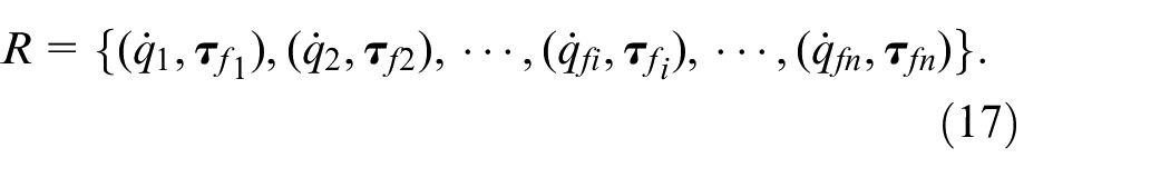
From equation (17), a dataset corresponding to different joint speeds and friction forces of the robot can be established. To improve the identification accuracy of friction, according to equation (11), which is the continuous differentiable friction simplified model, sets of experimental data (joint torque, joint speed) are sampled, and the unknown parameters are rearranged into linear form as follows:

where

where
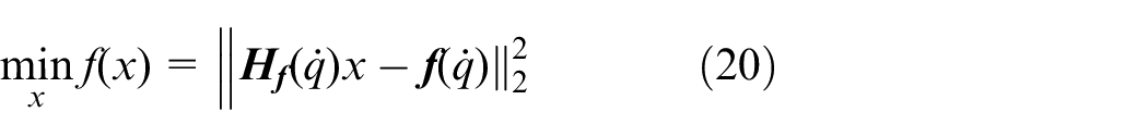
The optimal solution should satisfy
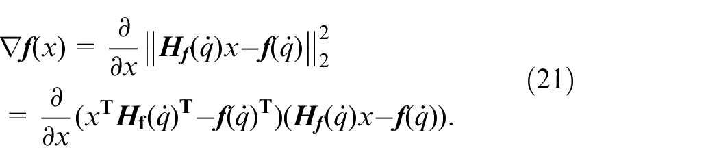
Equation (21) is calculated as follows:

The calculated result is given by

In addition,
Experimental results
Experiment platform
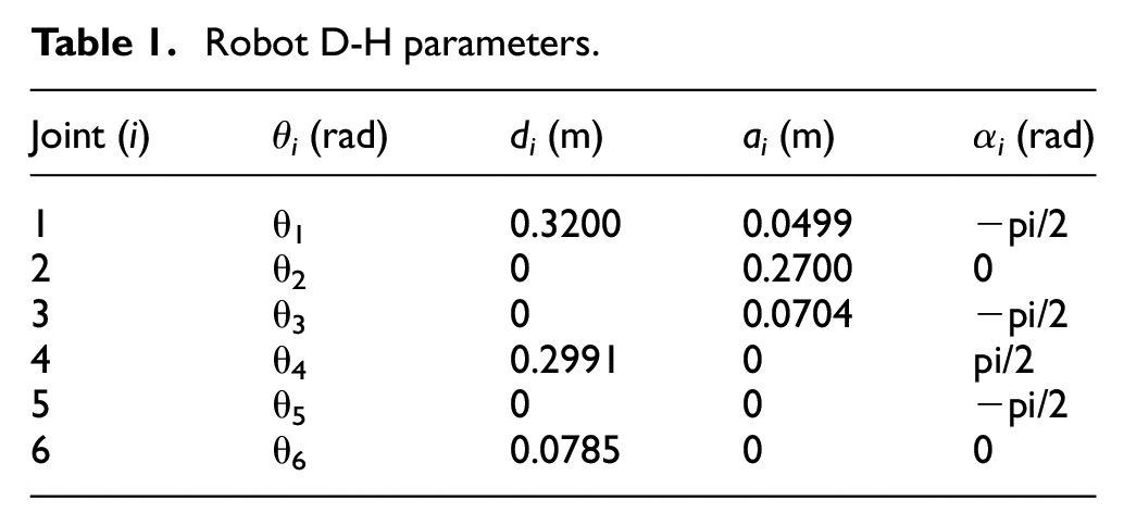
The experimental platform uses a light six-axis industrial robot. Its appearance and control system structure are shown in Figure 3, and the corresponding D-H parameters are shown in Table 1. The control system uses a semi-physical simulation control platform (Beijing Lingsichuangqi Technology, Ltd., LinksRT), running on VxWorks real-time operating system. The sampling period T of the industrial computer control (IPC) is 2 ms, and the EtherCAT bus is used for data communication with the six-axis force sensor and the robot servo drive. The experiment uses the SRI torque sensor to obtain the force feedback information under the force/position control of the robot and configures the M8128 acquisition card to preprocess the sensor data. The designed robot control algorithm can be directly compiled by Simulink to generate C code and then downloaded to the embedded industrial computer to run the program function.
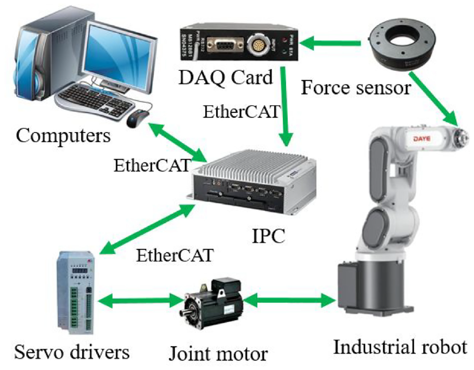
Robot system platform.
Robot D-H parameters.
Parameter identification
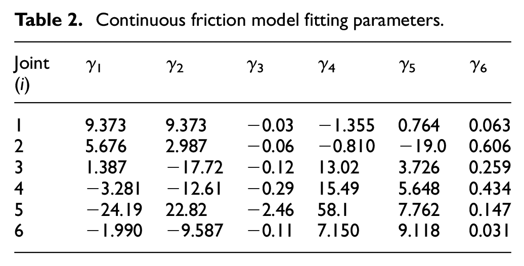
With the goal of accurately identifying the friction parameters of the joints, the angular velocity and torque information, shown in Figure 4, are used to control the six joints of the robot. This is done to perform joint reciprocating motions in the interval [−30°, 30°]. To avoid the inertia moment and centrifugal force from affecting the identification results, in this work, we intercept 60-segment constant speed part and the corresponding output torque in Figure 4 for data processing and fitting, and then take the average of the joint back and forth speed and torque data to obtain 30 data points. Then, the friction parameter vector set of the six joints is calculated according to the method proposed in Section 3.2. The fitting curve is shown in Table 2 and Figure 5. As shown in the figure, the method used has a better fitting effect.
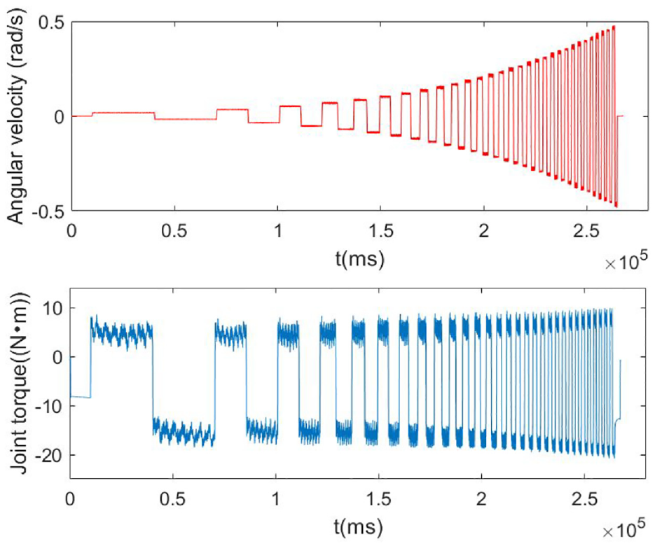
The robot’s joint velocities and torques.
Continuous friction model fitting parameters.
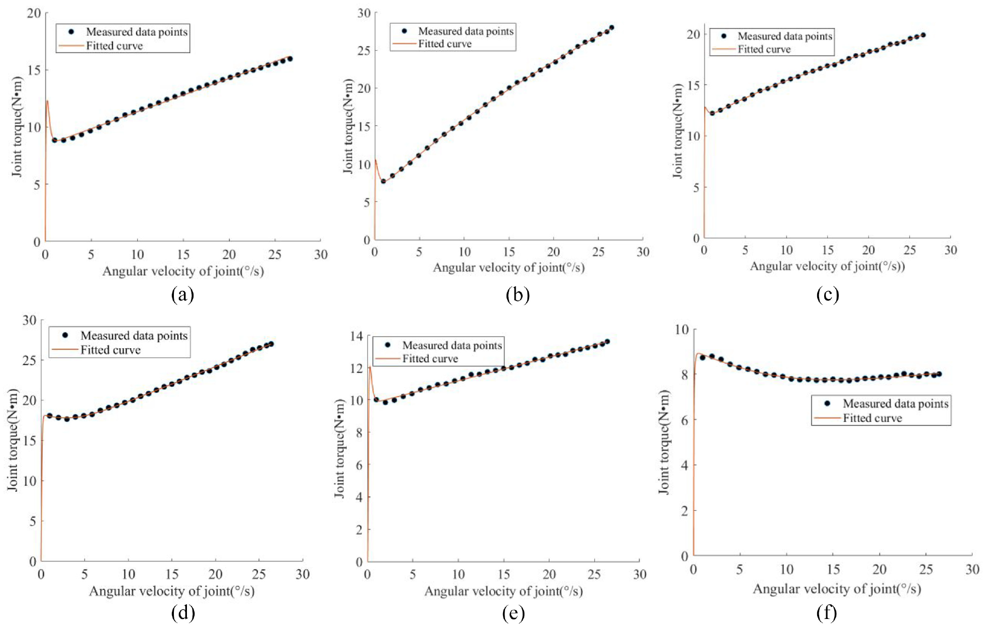
(a)–(f) Friction–velocity fitted curve for each joint: (a) Joint 1 fitted, (b) Joint 2 fitted, (c) Joint 3 fitted, (d) Joint 4 fitted, (e) Joint 5 fitted, and (f) Joint 6 fitted.
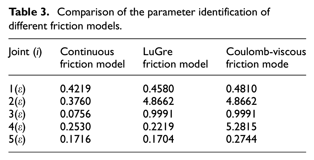
Next, the fitting residual square sum ε is introduced as a quantitative indicator of the degree of fitting of the friction model to further verify the fitting effect of the continuous friction model. Here, the closer the value of ε is to 0, the better the fitting effect. Comparing the continuous friction model, the LuGre friction model 24 and the Coulomb-viscosity model, 22 the results of fitting joints 1–6 are shown in Table 3. As can be seen, for the same torque and speed data set, the continuous friction model has the best fitting effect. However, in actual friction compensation experiments, the model parameters of the system will change with changes in conditions, such as lubrication, temperature, and external interference. The effectiveness of friction compensation must be further verified through experiments.
Comparison of the parameter identification of different friction models.
Experimental verification
Experimental scheme
According to the design scheme of the robot force/position hybrid control collision detection, the end of the robot is controlled to be polished along a certain smooth plane. We set the position control directly to a trajectory on the plane formed by the x-axis and the y-axis. The control sequence t1, the force control contact t2, and the disengaged contact t3 of the robot position sequence controller 1 range from 22 to 25, 25 to 53, and 53 to 58 s, respectively. The force control direction is the base coordinate system z-direction, to better verify the experimental results of collision detection under variable load, the force control output is set to: 27.8 N + 5sin(t)N, the control sequence segment of the timing controller 2 is 25.1–52.9 s, and the parameter of the PID controller is {5, 0.003, 0}, the admittance controller parameter is 0.002, and the effective sampling period n = 25 ms for collision detection is set. Because the control output force of the robot end-effector is equal to the reaction force of the polishing surface, a six-axis force sensor is used to detect the size of the robot control output force, as showed in Figure 6. It can be seen from the figure that the force control has a certain impact at the beginning, and the data of the detection output control force have certain fluctuations. With effective control of the robot force/position mixing, the detection data fluctuates around the desired control force and is generally stable. For the designed robot the force/position hybrid control effect is better.
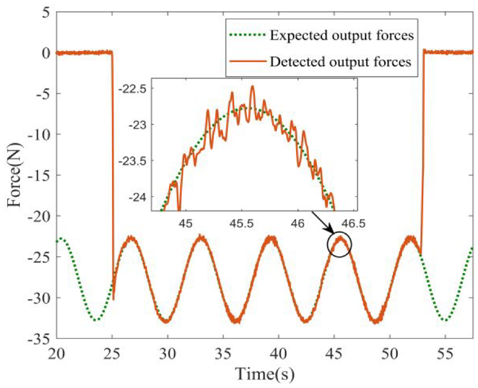
Sensor detection force control effect.
The change curves of the angle and angular velocity of the six joints under the force/position control of the robot are shown in Figures 7 and 8, respectively. During the force control contact period of 25.1–52.9 s, the speed and angle of joints 1 and 6 changed greatly, while the angles of joints 2–5 hardly changed. The angular velocity of the joints was small, and there was a slight change in the positive and negative alternates, which can be judged as follows: joints 1 and 6 of the robot perform the position control, and joints 2–5 mainly perform the force control of the robot. Therefore, according to the particularity of joint position control and joint force control in the application of robot force/position hybrid control, the robot joint friction compensation experiment and the robot collision detection experiment are carried out respectively.
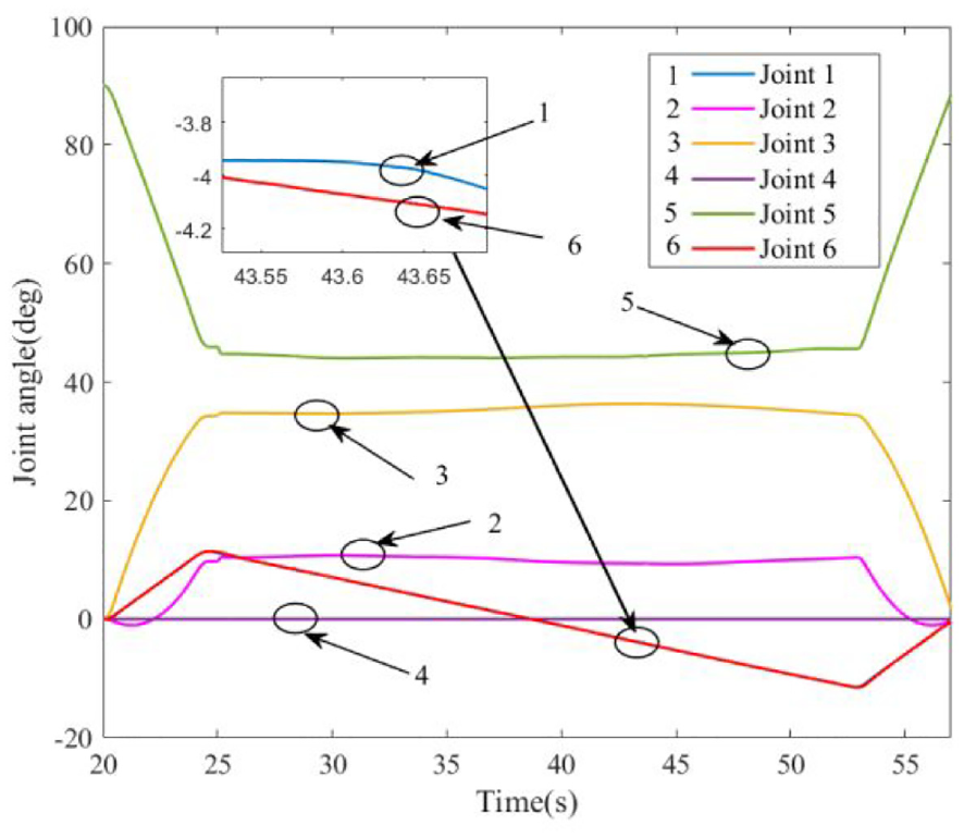
Joint angle curve.
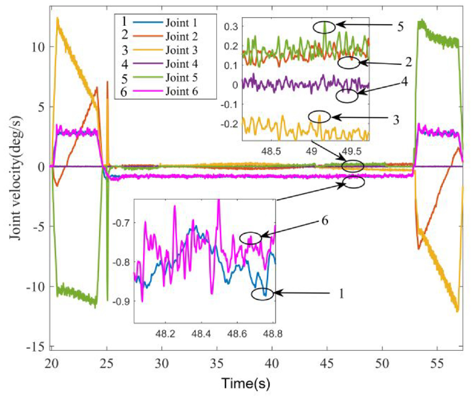
Joint angular velocity curve.
Joint friction compensation experiment
We verified the effect of the continuous friction model in dealing with the slow, reverse, and sudden changes in the joint speed and the effect of the compensation experiment on the three models of the continuous friction model. The results of applying the LuGre frictionmodel 24 and the Coulomb-viscosity model 22 are shown in Figure 9.
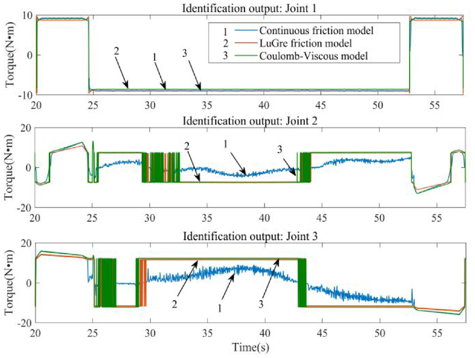
Continuous friction model and other friction model comparison curve.
In the entire time sequence, joint 1 of the robot is under position control, and the joint motion speed is continuous and stable. The three friction models can track the friction force well; when the force control contact A ranges from 25.1 to 52.9 s, joints 2 and 3 of the robot carry out force control, and their speeds have alternating positive and negative changes. The friction forces identified by the LuGre friction model and the Coulomb-viscosity model have positive and negative impacts as well as sudden changes; in comparison, the continuous friction model can better realize friction compensation.
Robot collision detection experiment
To verify the effectiveness of the robot force/position hybrid control application collision detection method, we use joints 1–3 as examples, set the force control output to 27.8 N + 5sin(t)N, and carried out the position when the force control contact ranged from 25.1 to 52.9 s. The experimental process of the collision detection in the control direction and the collision detection in the force control direction is shown in Figure 10.
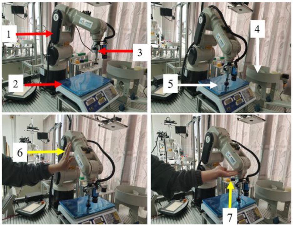
The process of robot collision detection experiment: (1) robot, (2) working plane, (3) force sensor, (4) position control direction, (5) force control direction, (6) collision, and (7) collision.
The results of the robot force/position detection experiment are shown in Figure 11. The collision detection thresholds of the robot’s joints 1–3 were set to 4, 8, and 8 N·m, respectively, and the collision detection of the robot’s position control direction and force control direction are at 32.2 and 44.8 s, respectively. When an artificial collision occurs in the position control direction at 32.2 s, the detected torque deviation of joint 1 exceeds 4 N·m, and the duration exceeds 25 ms, this means that an abnormal collision has occurred, and the torque deviations of joints 2 and 3 have slight fluctuations and exceed the set threshold. When an artificial collision occurs in the 44.8 s force control direction, the torque deviations of joints 2 and 3 respectively exceed the set 8 N·m threshold, and the duration exceeds 25 ms, this means that an abnormal collision occurs in the force control direction, and the torque of joint 1 fluctuates slightly. The collision detection effect of joint 1 is not obvious.
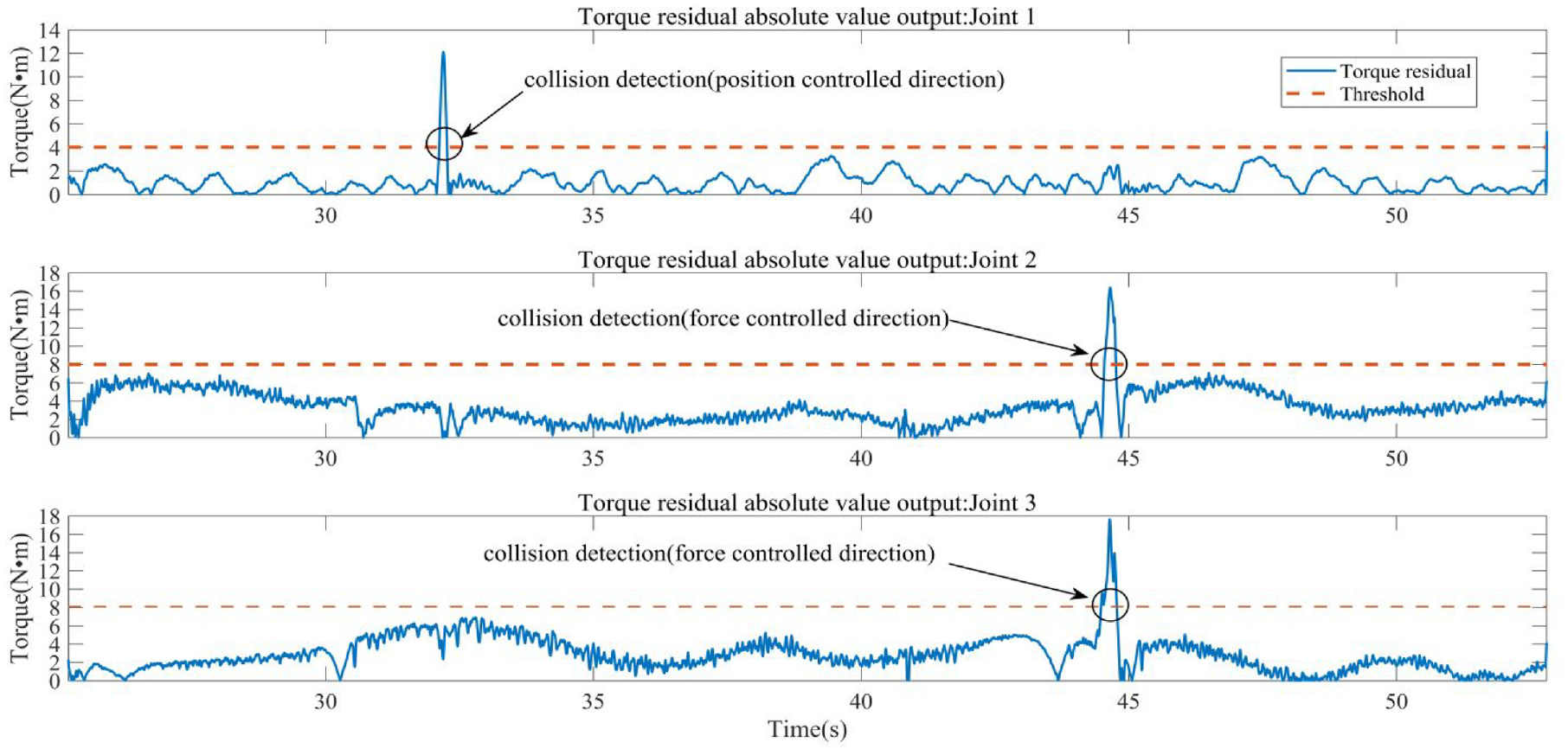
Collision detection for robot force/position hybrid control.
However, in the actual robot operation process, the collision of the robot does not strictly comply with the position/force control direction collision, and the collision direction is uncertain. According to the above scheme, in the actual robot force/position hybrid control working environment, collision detection is carried out randomly in accordance with the habits of human operation. The results of the four experiments are shown in Figure 12. As can be seen, the position control joint 1 detects that the torque deviation exceeds the set threshold four times within the continuous collision time, while the force control joint 2 and joint 3 detect collision detections two times and one time respectively. According to the collision detection equation described in equation (9), if only one joint detects that it exceeds the threshold, an abnormal collision of the robot is thus detected.
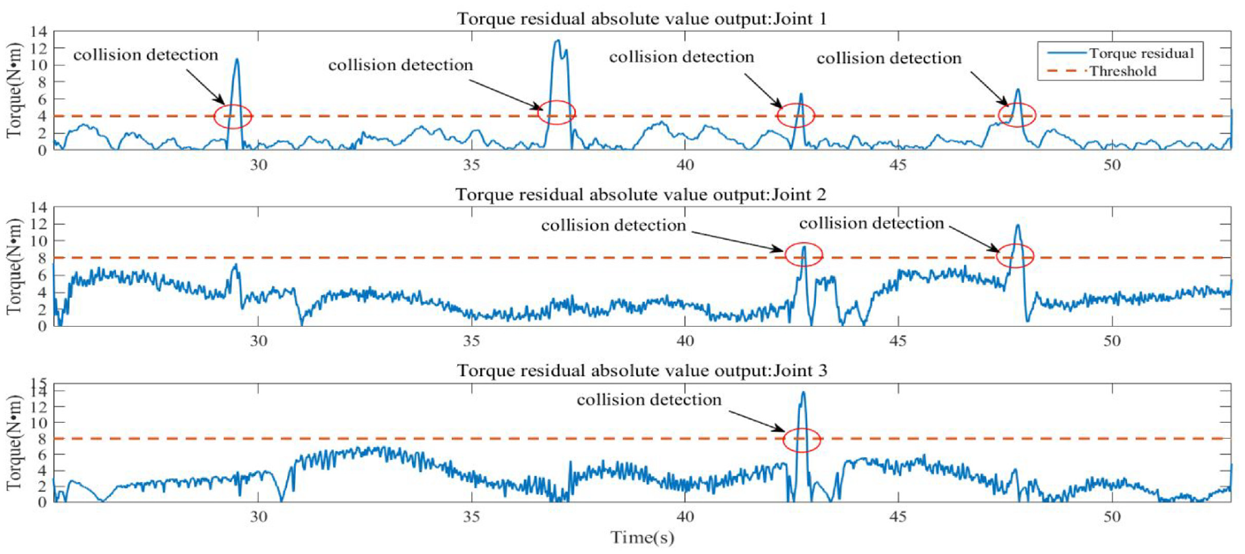
Random collision under robot force/position hybrid control.
Therefore, when the robot force/position hybrid control application security is applied, if a collision occurs in a strict force control direction, it would be necessary to monitor the torque change of the force control joint in real-time. If practicality and simplicity are taken into consideration, the collision detection model can be simplified, and only the torque changes of the robot position and direction control joints need to be detected. The experiment presented in this paper can detect abnormal collisions that exceed the threshold of 4 N·m or more by detecting only the torque changes of the position control joints. Doing so can better ensure the safety of the equipment and its operator under the mixed control of robot force/position.
Conclusions
This paper proposes a rapid and practical robot collision detection algorithm based on a dynamic model. Aiming at overcoming the complexity of robot force control joints, a feasible and applicable robot force/position hybrid control collision detection scheme is designed, and the continuous differentiable friction model is used to identify and address the joint friction problem. In doing so, we can improve the effect of dynamic model identification for force/position control. Under the application of different collision directions, a collision detection method is proposed to monitor the torque change of the position control joint and the force control joint respectively. Finally, using the light industrial robot as the experimental platform, joint friction compensation experiments and robot collision detection experiments were carried out to verify the effectiveness of the continuous friction model. Considering the practicality of the algorithm, the simplified model of the collision detection process only detects the torque change in the position control direction. There is a certain amount of engineering reference values to be considered to ensure safe production under actual working conditions. In the follow-up study, the dynamic threshold detection method of abnormal robot collision will be studied according to the dynamic characteristics of the robot force/position hybrid control. Furthermore, the accuracy of the collision detection method will be further discussed.
Footnotes
Declaration of conflicting interests
The author(s) declared no potential conflicts of interest with respect to the research, authorship, and/or publication of this article.
Funding
The author(s) disclosed receipt of the following financial support for the research, authorship, and/or publication of this article: This work was supported by the Research Program of the Natural Science Foundation Project of Ningxia Province (2022AAC03275, 2020AAC03201), National Natural Science Foundation of China (Grant Number U1713210), The University Synergy Innovation Program of Anhui Province (PA2019AGXC0125).