
Abstract
In order to improve the quality of the industrial robot automatic polishing on curved surfaces and ensure the constant polishing pressure during polishing process, a method for polishing complex concave cavity surfaces with industrial robot is proposed in this article. The method can achieve stable force control and precise position control and is easy to be realized online. In order to ensure the removal rate uniformity of surface material at different normal vectors, a method for adjusting the speed of motorized spindle in real time according to the surface normal vector is proposed. After planning the trajectory and normal vectors, combined with the feedback force signal from the sensor and the proportional–integral controller in the direction of the normal vector, the robot terminal tool corrects the trajectory in the direction of the surface normal vector, indirectly realizing force control between the tool and the surface. The robot polishing system with different polishing tools has different system stiffness. In order to ensure the polishing system with different stiffness to have a better tracking performance of the contact force, an adaptive proportional–integral control algorithm proposed in this article can be used to evaluate the stiffness of polishing system and to adjust proportional–integral parameters. The simulation and experimental results indicate that the method can realize the polishing of concave cavity surface commendably.
Keywords
Introduction
Electronic products and vehicles have an increasing demand for parts of high-quality surface, especially for workpieces with small-sized concave surfaces such as moulds, the surface quality of which is particularly important. 1 So, as a process of improving the surface quality, polishing process is very important. However, nowadays, the concave surface polishing is mainly completed by skilled and experienced workers manually. Manual polishing process depends on the technical level of workers, and it is difficult to avoid low production efficiency, unstable processing quality and other issues. Today’s industrial development requires low cost, short cycle and high quality on the concave surface manufacturing. Manual polishing is difficult to meet these requirements. 2 Aiming at this situation, automatic polishing of curved surfaces has attracted much attention from the companies and institutions concerned. For example, Domroes et al. 3 applied and analysed the force control strategy of deburring and grinding. The experimental system is made up with ABB IRB 4400 industrial robot loaded with 60 kg and its related force control application package. Tian and colleagues4,5 built a flexible polishing system based on force control. The KUKA KR30-3 industrial robot is the main actuator. It controls computer through TCP (Transmission Control Protocol)/IP (Internet Protocol) communication protocols to realize the dynamic communication with the robot data, based on the robot sensor interface (RSI) control technology development kit provided by the manufacturer, changing the movement state of the robot in real time. The polishing experiment system developed by Nagata et al. 6 is based on the industrial robot Motoman UP-6 with the open control structure. The advantage of this industrial robot is that it provides several useful Windows application programming interface (API) functions, such as kinematics and a servo control based on Cartesian coordinate. This advantage makes engineers more convenient and flexible to study the robot system control algorithm. To carry out the robot surface product polishing, the processing path planning is the primary problem to be solved and is unavoidable.
Nagata et al. 7 developed a robot computer-aided manufacturing (CAM) system, which is the integration of computer-aided design (CAD)/CAM system pre-processing, robot servo control system and robot kinematics. The robot CAM system can realize the precise tracking of robot trajectory without robot teaching and control language.
Neto and Mendes 8 developed a new robot programming system based on CAD, generating robot program through the mapping from CAD graphics to the actual environment. The purpose is to make it easy for people who know a little about CAD software and robotics to use robots better.
Feng 9 presented the improved method of the equal residual height processing path. In view of the different conditions of surface, the calculation process of the cutter locations is deduced, and the method of avoiding interference is put forward. The machining path method was integrated into the CAD/CAM/computer-aided engineering (CAE) system through customization.
Yun et al. 10 presented the development of an augmented reality-based robotic work cell. The kinematics of the robot arm was realized using Denavit–Hartenberg’s theorem, which enables complete manipulation of the end-effector in three-dimensional space when interacting with other virtual machines.
Due to the poor position accuracy of the robot polishing system, using the pure position control cannot meet the requirements of surface polishing, so the robot’s force control is applied to polishing process.
Nagata’s article proposed an impedance model of velocity and polishing force. Through the impedance model, the polishing force (between the mould to be polished and the polishing tool) and the velocity along the normal direction of the surface are adjusted to polishing the mould.
Du et al. 11 had known the weight and the load of the centre of gravity. According to the attitude of the robot, the influence of gravity was calculated in real time, and the influence of gravity on the force and torque of the six-axis force sensor was eliminated. In general, the weight and the centre of gravity are not known and need to be measured online.
Tian et al.12,13 used an anti-saturation integral separation fuzzy PI (AISFP) controller to transform the force signal to the end trajectory correction along the direction of the normal vector, realizing the force control of the normal vector direction indirectly. The direction of the normal vector can be reversed through force signal. Fuzzy control can achieve the adjustment of control parameters, and then achieve constant force polishing.
Mohammad et al. 14 designed a novel force-controlled end-effector for automated polishing processes. By integrating a force sensor, the polishing force was measured and fed back to the controller to regulate it according to the polishing pre-planned requirements.
In this article, the principle of the polishing trajectory obtained from the CAD/CAM software (such as UG) secondary development is explained. A method of obtaining a force signal for surface polishing has been studied, through compensating the force signal measured by the sensor with the gravity of the polishing tool. The material removal rate of the surface has been analysed. In order to ensure the removal rate uniformity of surface material, a method of adjusting the speed of motorized spindle according to the normal vector has been proposed. In this article, the force control of the normal vector direction on the concave surface and the position control along the polishing trajectory have been realized, based on the normal vector of the surface and the force–position hybrid control algorithm of the robot position controller. Aiming at the difference of the stiffness of the polishing system with different polishing tools, an adaptive force–position hybrid control algorithm which adjusts control parameters according to the system stiffness evaluation has been proposed. Finally, the surface polishing experiment has been carried out in the robot polishing system. The results indicate that the force–position hybrid control algorithm proposed in this article can track the contact force and improve the quality of the workpiece surface dramatically.
Trajectory generation
Small-sized concave surface product is regarded as research object, and a spherical polishing tool is selected in this article.
15
Figure 1 shows that in the workpiece coordinate system,
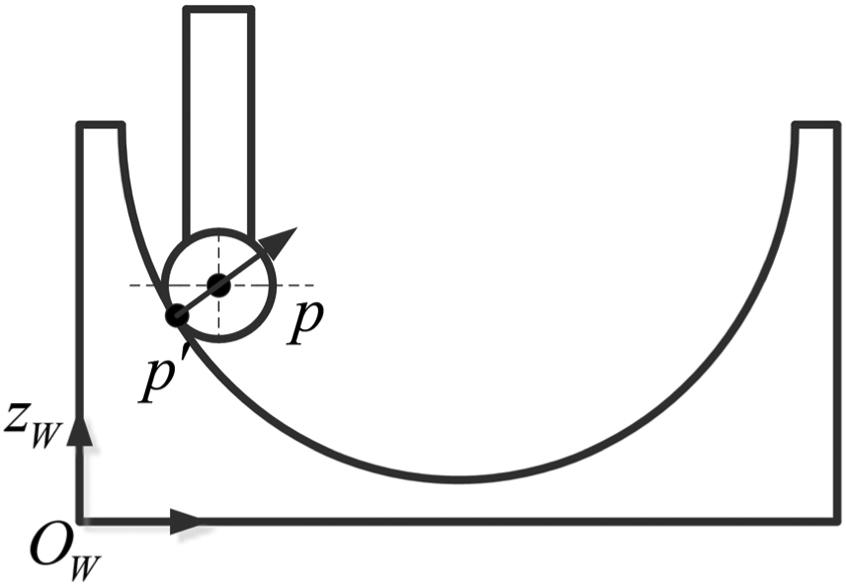
Tool compensation.
In Figure 1,
The normal vector of the surface at this point is expressed as

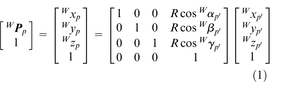
If the homogeneous transformation matrix of the workpiece coordinate system {W} relative to the robot base coordinate system {B} is
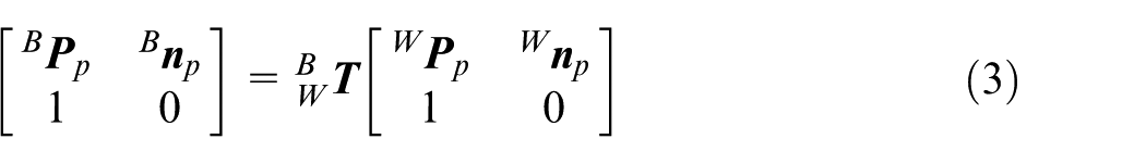
The posture of the polishing tool during the processing process is shown in Figure 2; in order to avoid the interference between the polishing tool and the curved surface during the polishing process, the pose of the polishing tool coordinate system {T} is kept invariant. Supposing that the
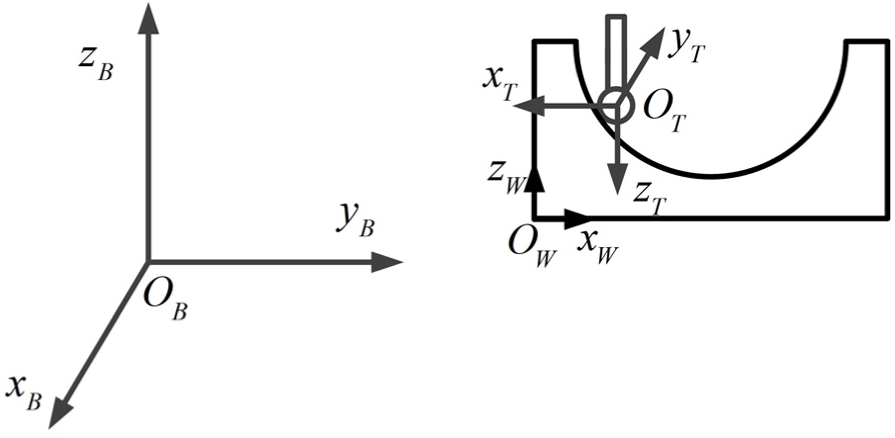
Posture of the polishing tool during the processing process.
Supposing that the roll–pitch–yaw (RPY) angle of the constant rotation matrix R is
Surface polishing strategy
Force signal measurement and gravity compensation
A spherical polishing tool is used for polishing in this article. During the polishing process, the polishing tool is kept perpendicular to the level downward. ME3DT120 3-axis force sensor is used to measure the contact force between the workpiece and the polishing tool. Figure 3 illustrates the force of the workpiece surface on the polishing tool.
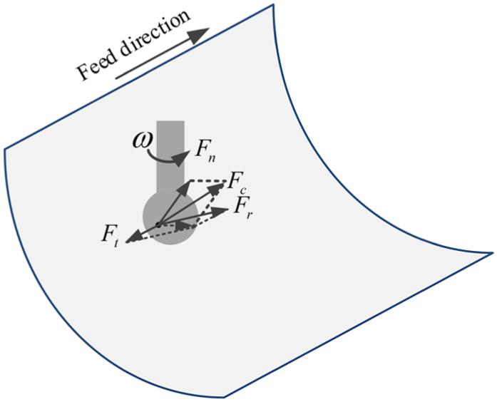
Force of the workpiece on the polishing tool at the point of contact.
The force of the workpiece on the polishing tool is

During the process of the robot processing, the force sensor is installed between the polishing tool and the end of the robot, measuring the force


where

During the polishing process, the gravity of the polishing tool has great influence on the polishing force
Research on material removal rate
During the processing process of the concave surface product, the axis of the motorized spindle is parallel to the z-axis of the base coordinate system. The angle between the normal vector at the polishing point of the curved surface and the axis of the motorized spindle is
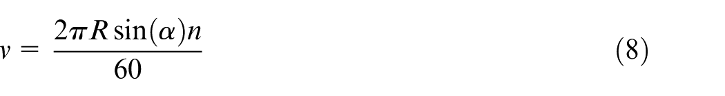
During the polishing process, the polishing point changes constantly. If the motorized spindle uses a uniform speed, according to equation (8), the relative velocity between the polishing tool and the polishing point of the curved surface will inevitably change with the normal vector of the surface to be polished.
According to the assumption of Preston, the model of material removal rate is built. While polishing, the relationship between the material removal rate and the related process parameters could be expressed as follows
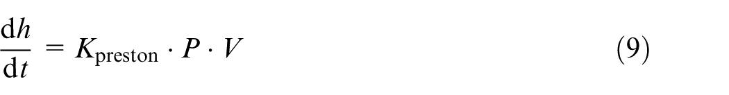
where
It is indicated that the material removal rate is directly proportional to the polishing pressure (P) and the relative speed (V) in equation (9). In the polishing process, maintaining a stable material removal rate is conducive to ensuring the surface quality of the material. Through experimental study, the surface quality of materials is also affected by the positive pressure and relative velocity of polishing. Single-factor experiment of key process parameters indicates that the surface quality of machined materials increases with the increase in relative speed. But when the speed is too high, the surface quality is reduced. It is similar to the polishing pressure. The surface quality of workpiece first increases with the pressure and then decreases. 17 So, proper process parameters are of great importance to the material removal rate and surface quality.
It can be seen from equation (9) that when the pressure between the polishing tool and the concave surface is kept stable and the speed of the motorized spindle is constant, the velocity of the tool is different at Position 1 and Position 2. The material removal rate and the attrition rate are significantly different. Therefore, it is necessary to adjust the speed of the motorized spindle according to the normal vector of the surface so as to ensure the same speed at Position 1 and Position 2, so as to ensure that the removal rate of the materials is similar at Position 1 and Position 2. Based on the same velocity at the two positions and equation (8), the following equation can be derived

It can be learned from equation (10) that
Force–position hybrid control and simulation based on position
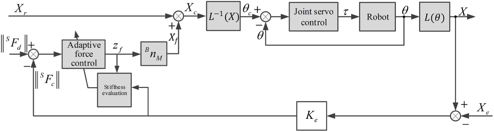
It can be seen from the analysis on the model of material removal rate that when the relative speed between the polishing tool and the surface to be polished is kept invariant, the polishing force is a key factor to determine the workpiece surface quality. The unstable contact force will lead to uneven material removal rate. So, in order to ensure the uniformity of the surface to be machined, during the whole polishing process, it is hoped that the robot will realize precise position tracking and constant force contact at the same time. A force–position hybrid control scheme based on position suitable for industrial robot polishing is proposed in this article. The control block diagram is shown in Figure 4.
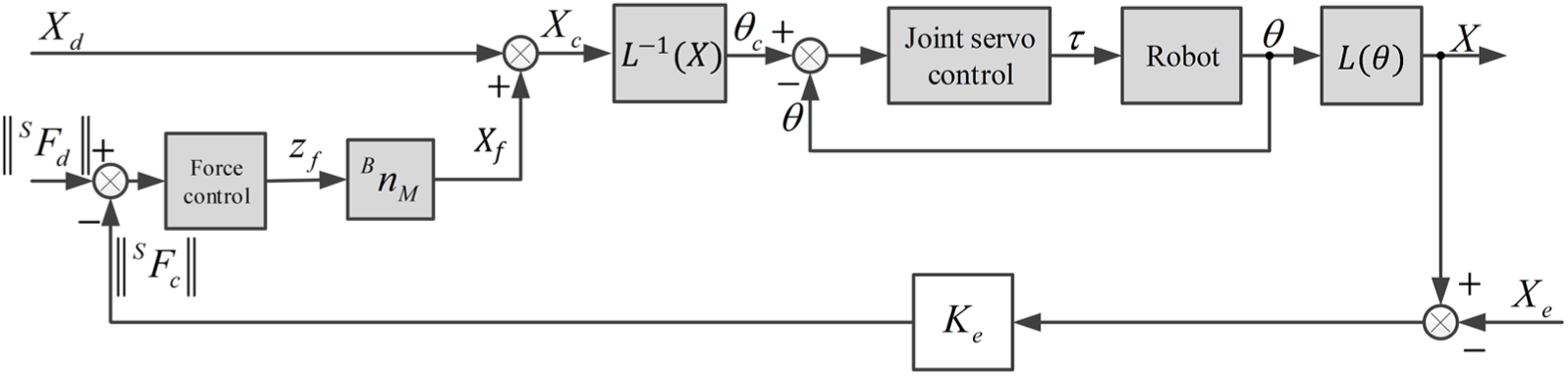
Block diagram of force–position hybrid control.
Supposing that the position
As shown in Figure 4,
The revised trajectory
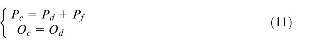
where
Due to the higher position tracking performance of industrial robots, the control of the surface normal force can be indirectly achieved by the control of trajectory correction value
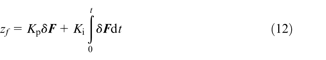
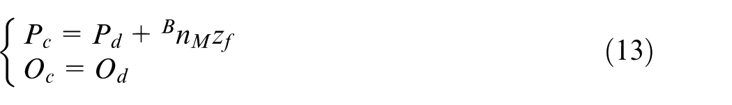
It can be seen from equation (13) that the trajectory correction value will be generated along xyz 3-degrees-of-freedom through the PI controller in the force control subspace.
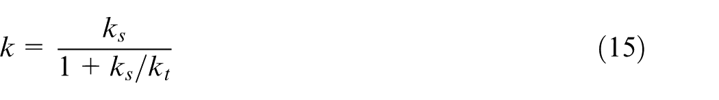
For the robot polishing system, the system stiffness k is a comprehensive result and depends on the stiffness of workbench, workpiece, polishing tool, force sensor and robot itself. Supposing the stiffness of other equipment is high enough, the system stiffness is approximately a synthesis of the sensor stiffness
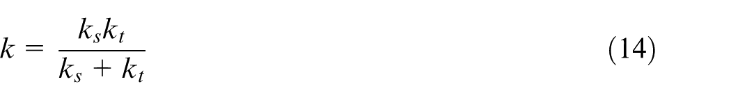
To learn the range of the system stiffness, equation (14) is transformed as follows
When the polishing tool is made of diamond, oilstone or grinding wheel, the stiffness is greatly high, namely,

When the polishing tool stiffness is small, such as Spongia, namely,

So, the stiffness of the system may vary between several orders of magnitude less than the stiffness of the sensor.
When performing a polishing operation, the system will use different polishing tools according to different machining requirements, such as wool spherical polishing tool, rubber abrasive spherical polishing tool and rubber spherical polishing tool. According to equation (15), the stiffness of the system is different while using different polishing tools. The following is the relationship between the displacement and force of the system in which the end of the robot is equipped with a wool ball polishing tool and a rubber abrasive polishing tool, where the angle is 45° between the surface normal vector and the base coordinate system. 18 Figure 5 shows the relationship between displacement and force where the robot is equipped with different polishing tools. Figure 6 indicates the relationship between displacement and stiffness with different polishing tools.
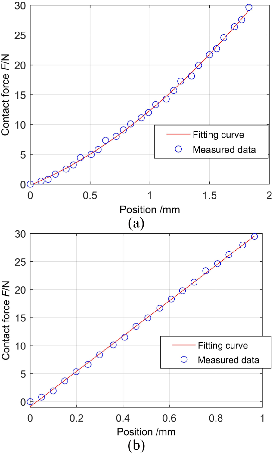
Relationship between the displacement and the force of the polishing system with different tools: (a) wool spherical polishing tool and (b) rubber abrasive spherical polishing tool.
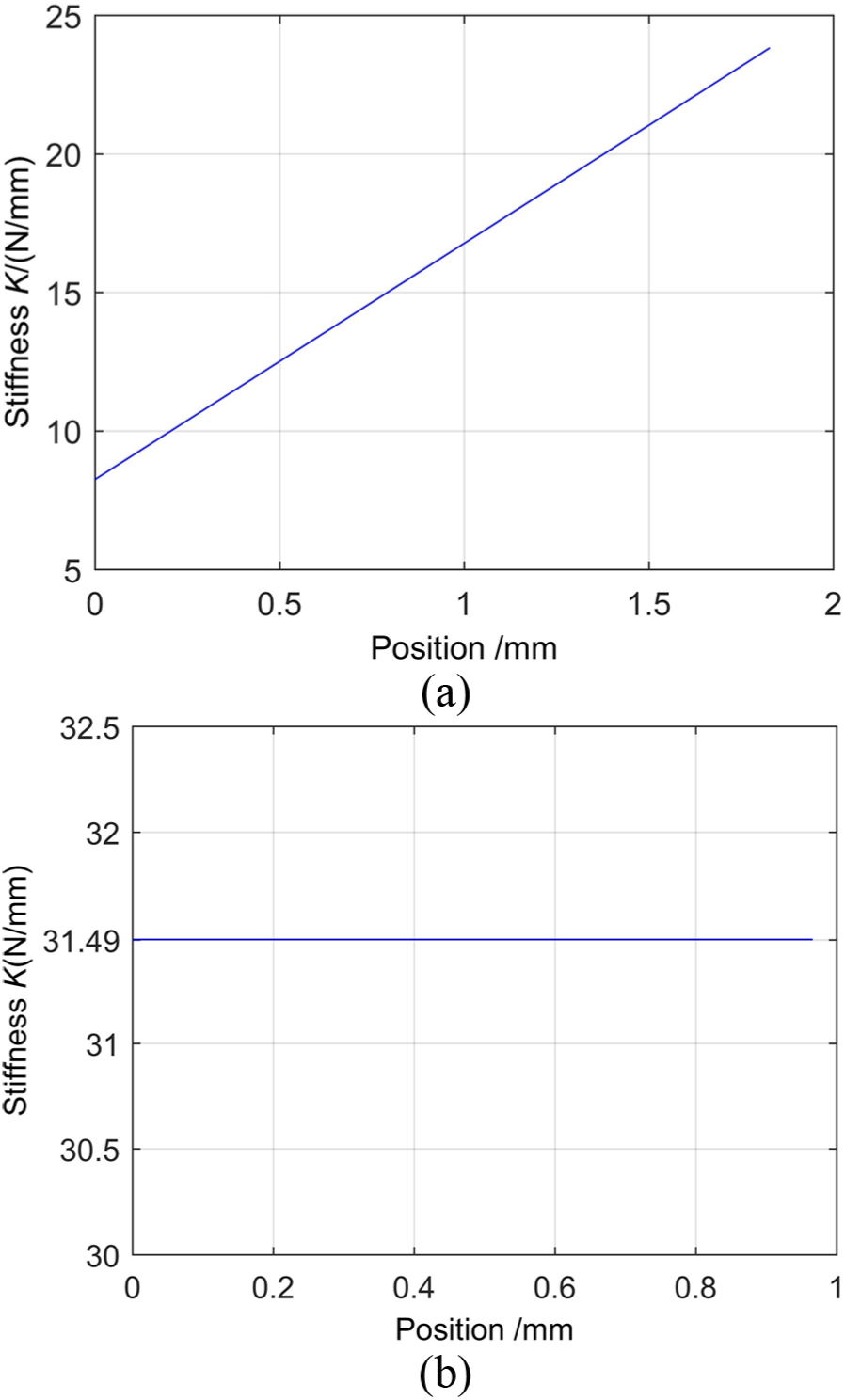
Relationship between the displacement and the stiffness of the polishing system with different tools: (a) wool spherical polishing tool and (b) rubber abrasive spherical polishing tool.
The zero point of the displacement in Figures 5 and 6 is the first contact point between the polishing tool and the workpiece. The relationship between the displacement and the force is obtained, using the least-squares method to fit the measured data in MATLAB (as shown in Figure 5). It can be seen from Figure 6 that the stiffness of the polishing system will increase with the polishing tool displacement along the surface normal vector. The system stiffness which is equipped with different material polishing tools is highly different.
Due to the eccentricity of polishing tool, rotation and oscillation of the motorized spindle and other unpredictable issues, the zero point of the polishing tool coordinate system will experience a minimal, continuous and complicated change in the direction perpendicular to the axis of the motorized spindle. In order to realize simulation, the change is simplified. Supposing that the changing rule is sine signal

where a is the amplitude of the vibration in the direction perpendicular to the axis of the spindle. The value of a is very small and is set to 0.1 mm, and b is the angular frequency, supposed to be proportional to the spindle speed. When the angle between the surface normal vector and the z-axis of the base coordinate system is 45°, the speed of the spindle is set as
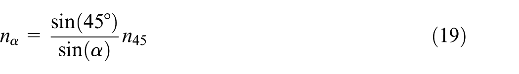
Then, the angular frequency
According to geometric knowledge, the maximum of the vibration amplitude at

The vibration changing rule of the polishing toll at
The simulation model of the force–position hybrid control based on position is established in Figure 7. The simulation conditions are as follows: the reference trajectory is a line segment 10 mm in length parallel to the x-axis of the robot base coordinate system. The angle
Simulation model of the force–position hybrid control based on position.
The polishing force of the polishing system varies with time, which is illustrated in Figure 8. Figure 8(a) shows the relation curve of the polishing force change with the wool spherical polishing tool and Figure 8(b) shows the relation curve of the polishing force change with the rubber abrasive spherical polishing tool. It can be seen that the robot does not contact with the workpiece within 0–1 s and moves in the free space. When the robot is equipped with the wool spherical polishing tool, the steady-state deviation is within
Contact force varying with time: (a) contact force with wool spherical polishing tool and (b) contact force with rubber abrasive spherical polishing tool.
Through a large number of simulation experiments, it is found that the different stiffness of the polishing system has a greater impact on the polishing force control. Generally, the larger PI parameters are suitable for systems with small stiffness, but smaller parameters are suitable for systems with high stiffness. If the PI parameter, which is suitable for system with small stiffness, is used in systems with large rigidity, the system may oscillate violently and even affect the stability of the system. If the PI parameter, which is suitable for system of high stiffness, is used in systems with small stiffness, the stability of the system may not be affected, but the response of the system to the various disturbances is slower. In order to ensure the good dynamic performance of the system, it is generally desired to adjust the PI parameters according to the stiffness of the system with different polishing tools.
As shown in Figure 9, a simple and feasible adaptive force control method is proposed to adjust parameters according to the system stiffness evaluation.19,20 The parameters are as follows
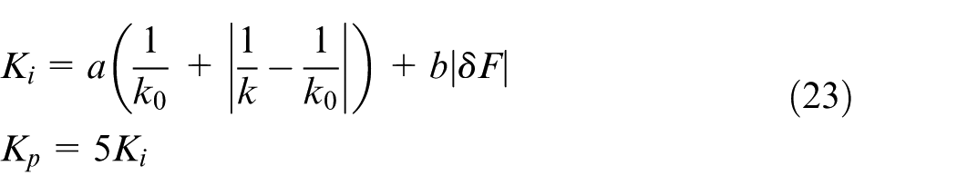
where
Adaptive force–position hybrid control based on position.
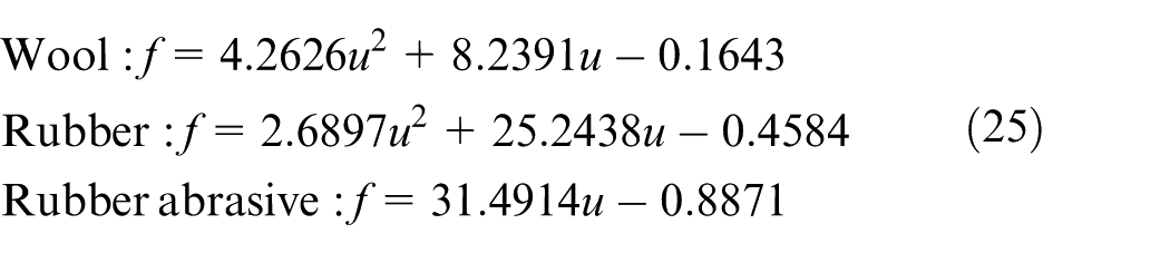
Supposing that the functional relationship between the amount of compression and the contact force of the polishing system along the normal direction meets the following polynomial

where u is the amount of compression along the normal direction, and f is the contact force. The functional relationship between the amount of compression and the polishing force is fitted through the least-squares method. The functional relationship between decrement and contact force is fitted through the least-squares method in the normal direction of the surface. The system is equipped with wool spherical polishing tool, rubber spherical polishing tool and rubber abrasive spherical polishing tool
Similarly, the functional relationship between the stiffness and contact force of various polishing tools is fitted as follows
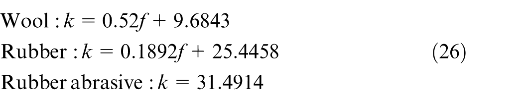
where k is the system stiffness.
The curve of the system stiffness of three tools varies with the contact force, which is shown in Figure 10.
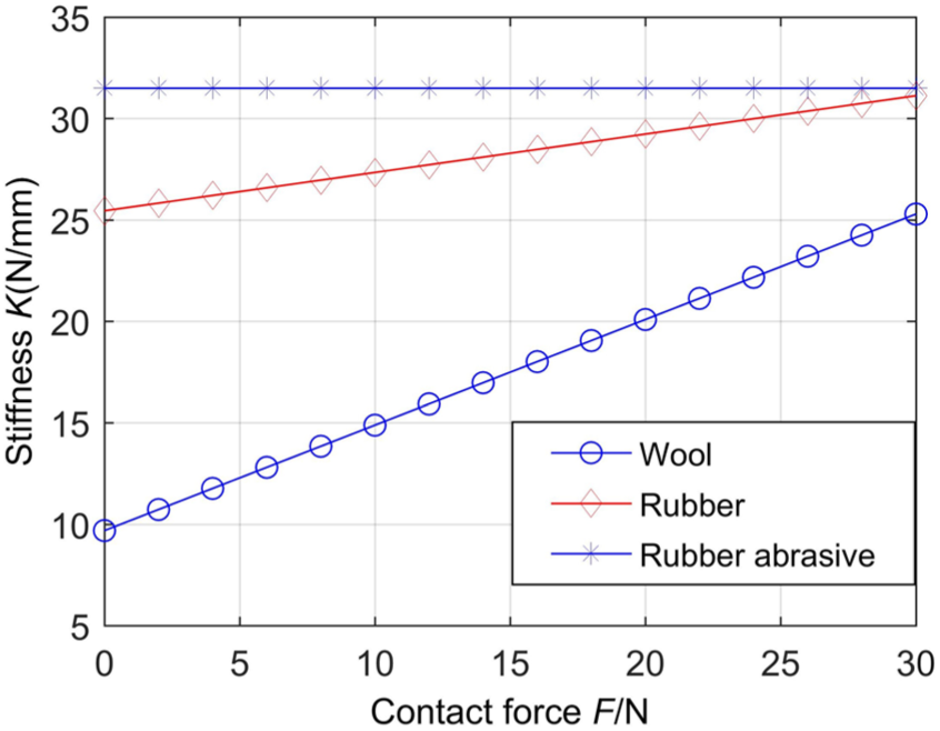
Stiffness of three tools varies with the contact force.
The estimation of the stiffness of the whole polishing system is divided into two parts: (1) the judgement of polishing tools and (2) the estimation of the stiffness. The judgement of tools is to determine which tool is used for polishing mainly through equation (25). The estimation of stiffness is to calculate the stiffness of the corresponding tool through substituting the expected force to equation (26) after determining the tool.
At the beginning of the polishing process, the contact force is calculated through equation (25). A certain amount of data are taken to calculate the sum of absolute value of the deviation between the contact force f and the actual contact force
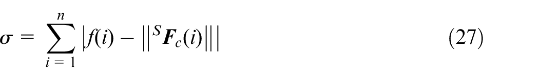
The polishing tool corresponding to the minimum
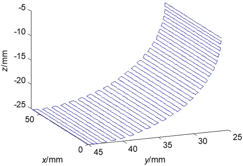
Supposing that the object to be polished is a concave surface with its internal diameter of 50 mm fixed on the worktable. The simulation trajectory is shown in Figure 11. In order to ensure the stability of polishing force and the surface quality during the polishing process, a line segment consisting of machining points is used as the machining unit. The normal vectors of these points are the same along the axis of the surface. In Figure 11, a series of line segments parallel with the axis is used to be the machining unit. The polishing tool processes from point A to point B, and then transits from point B to point C. Afterwards, the tool processes from point C to point D. Continuous machining is performed in this manner. The difference in the angle between the normal vector and the z-axis of the base coordinate system at two parallel machining points is 1°. The length of the parallel segment is 10 mm. At the beginning and the end, the angles
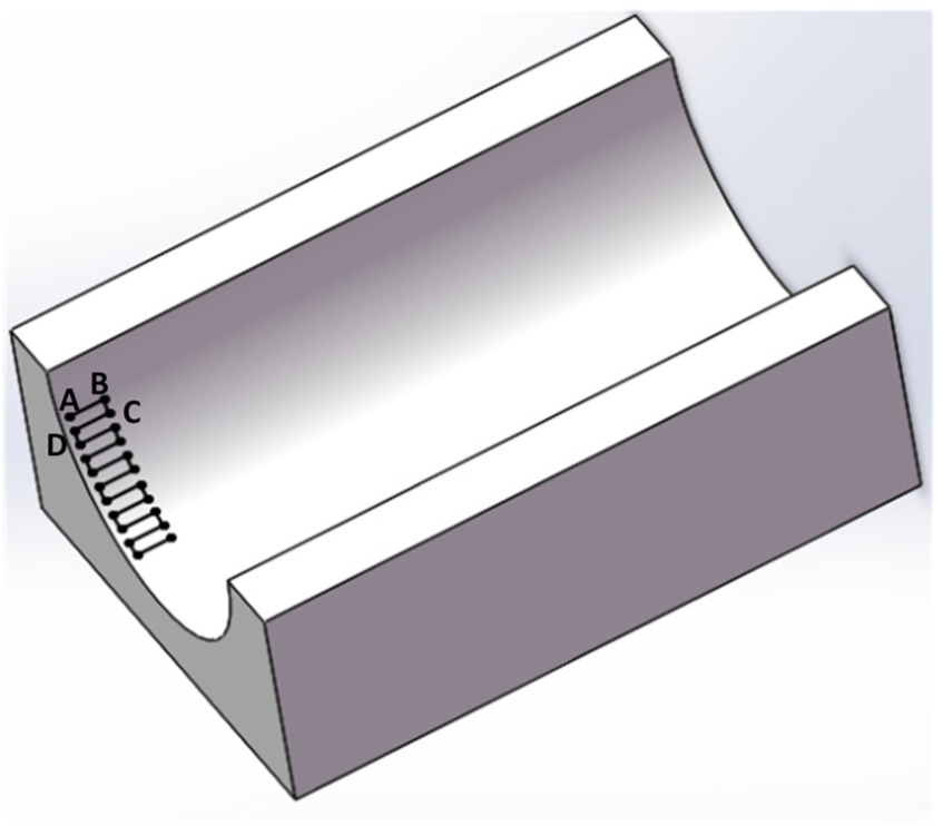
Trajectory planning based on UG model.
The simulation model of adaptive force–position hybrid control based on position is shown in Figure 12.
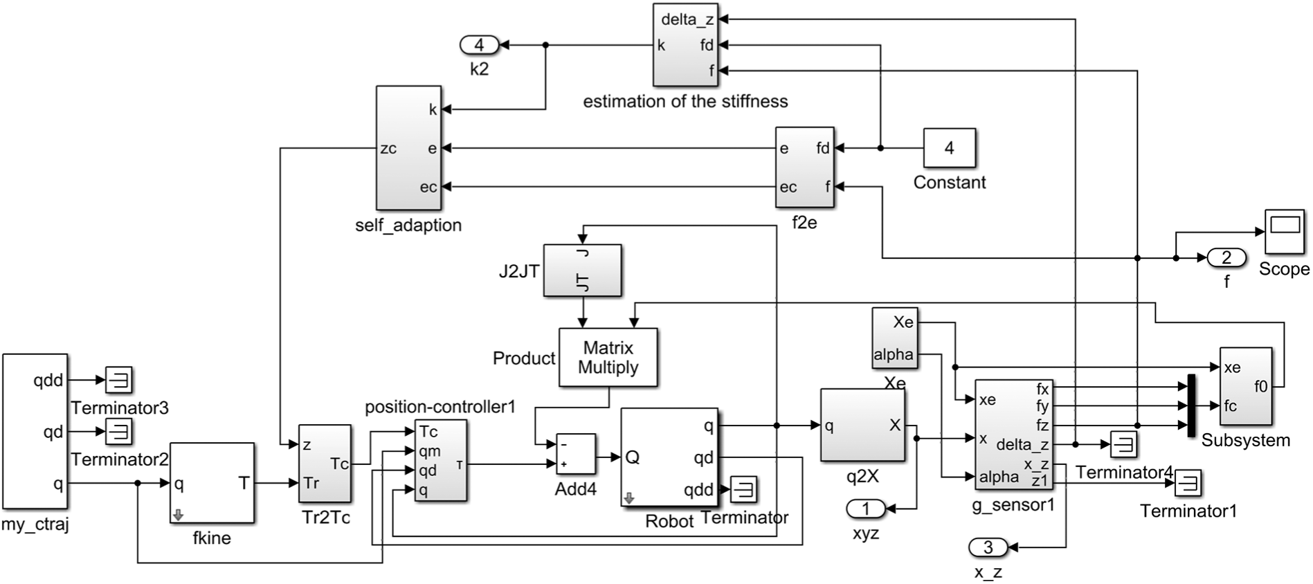
Simulation model of adaptive force–position hybrid control based on position.
Figure 13 shows the machining trajectory along the surface normal vector with
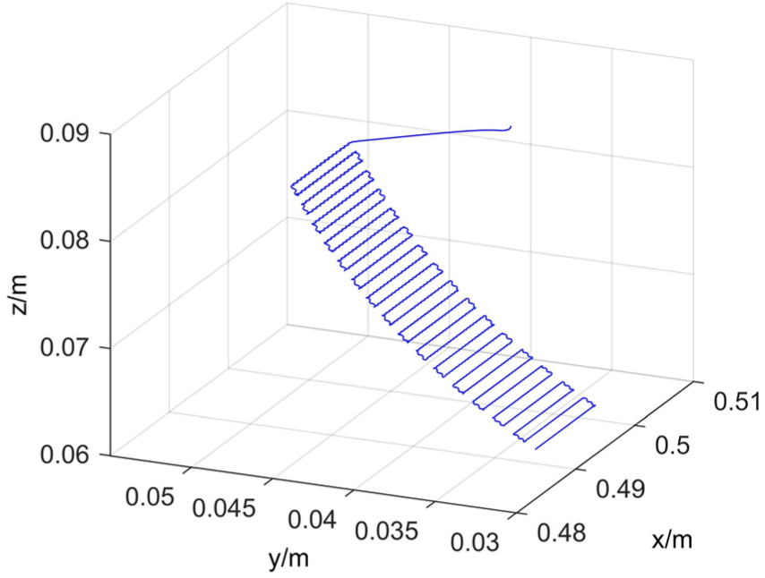
Motion simulation trajectory of robot.
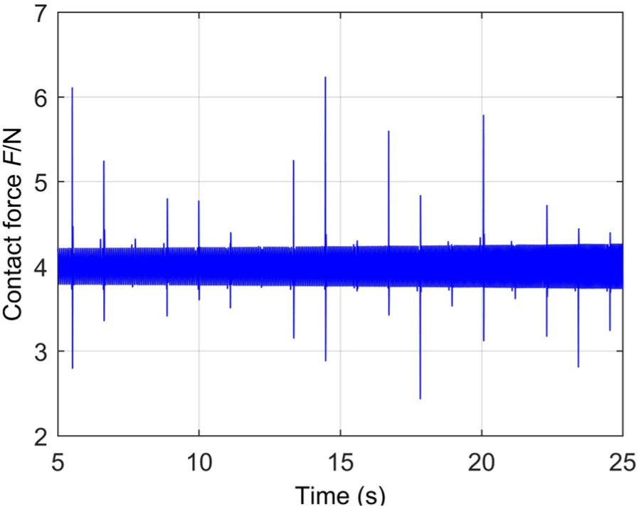
Polishing force varying with time.
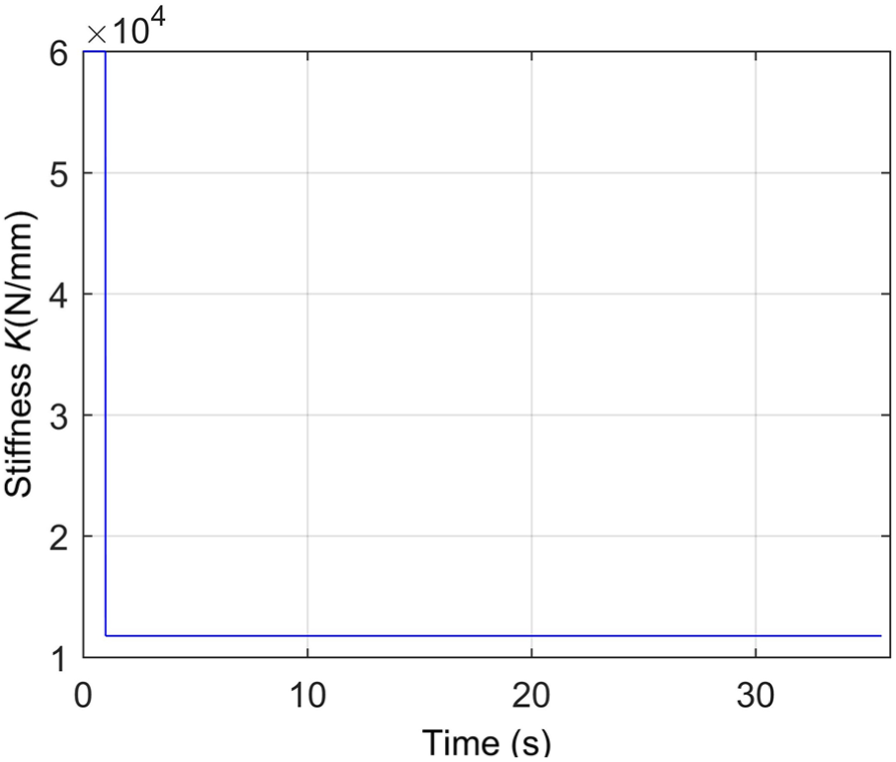
System stiffness varying with time.
Robot surface polishing experiment
Robot automatic polishing system
The robot automatic polishing system consists of two parts: robot system and additional parts. It is made up of robot body, host computer, control cabinet, polishing tools (motorized spindle and polishing head), ME3DT120 3-axis force sensor, signal amplifier, PCIe-6320 data acquisition card and E550-2S0004 (B) frequency converter.
First, through tool compensation and workpiece coordinate system calibration, the reference trajectory based on UG is converted into the reference trajectory based on robot coordinate system. When the end polishing tool is not in contact with the workpiece, the robot moves from the stopping point to the first machining point according to the reference trajectory. In order to avoid the damage of workpiece and polishing tools caused by the contact force and the oversize overshoot of the contact force, when the polishing tool is in contact with the workpiece surface, the movement speed is reduced. When the end polishing tool is in contact with the workpiece, the contact force signal of the three-axis force sensor is transmitted to the computer for processing through the PCIe-6320 data acquisition card. The processed force is used as the input of force control algorithm to modify the original reference trajectory. The modified trajectory is transmitted to the control card through Ethernet to drive robot’s six-joint motions, indirectly realizing the constant force control.
Surface polishing experiment
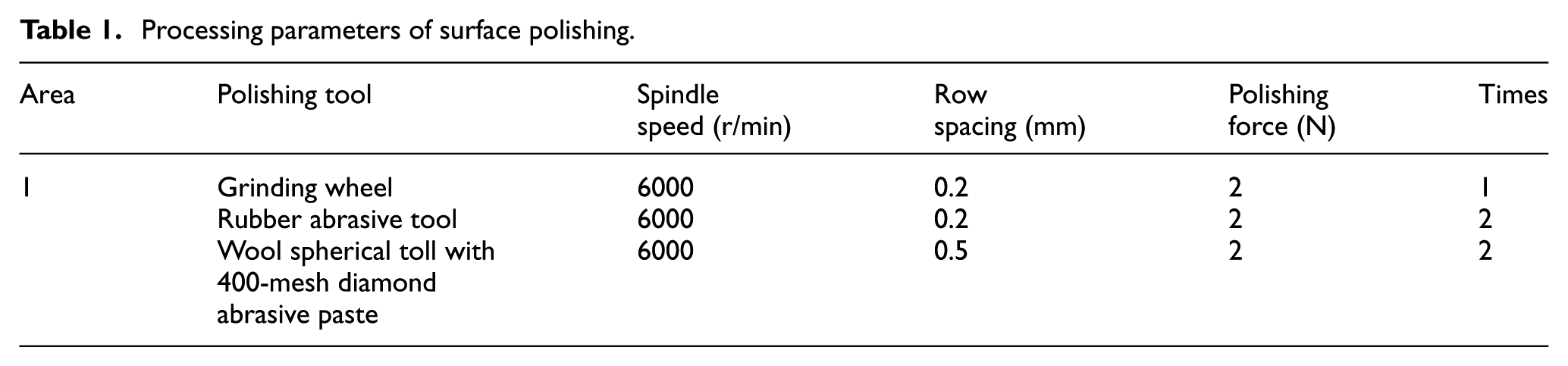
The polishing trajectory diagram of the surface polishing experiment is shown in Figure 16. For comparison, one side of the curved inner diameter sample is polished in this experiment. Grinding wheel is first used to the process, and then rubber abrasive ball polishing tool and wool spherical polishing toll are used to finish polishing the surface of part. Table 1 shows the processing parameters.
Surface polishing trajectory.
Processing parameters of surface polishing.
The contact force during the polishing process with spherical wool is shown in Figure 17. The expected contact force in polishing process is 4 N. It can be learned from the figure that most fluctuation range of the contact force is within ±2 N except a few data points.
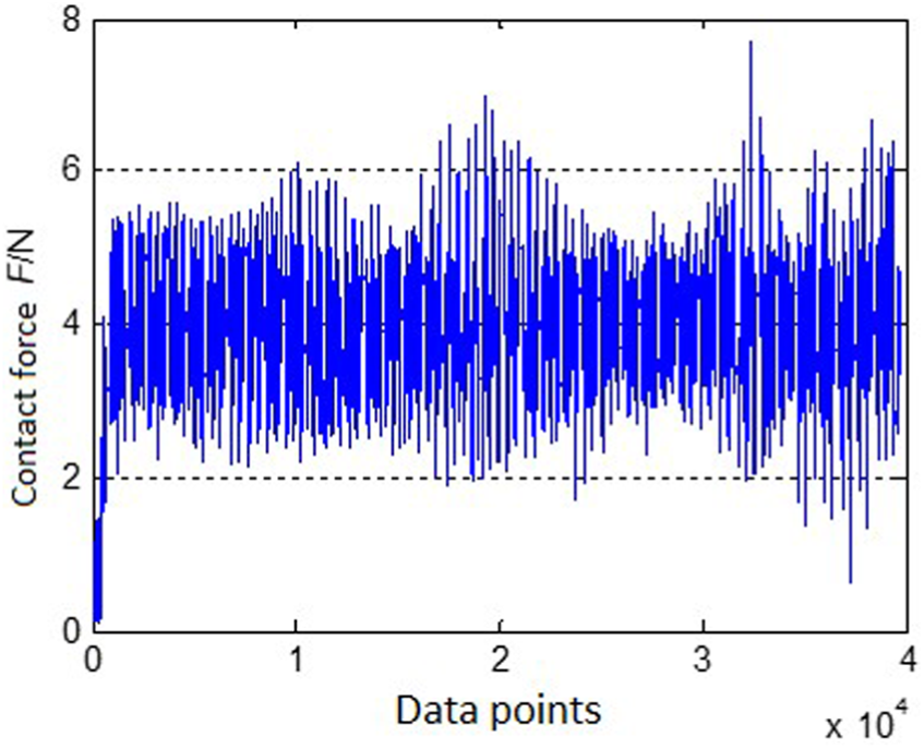
Contact force during the polishing process with the wool spherical polishing tool.
In Figure 18, the area 1 on the left of the parting line is the processed surface and the area 2 on the right is the unprocessed surface.
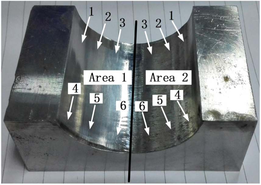
Concave surface after machining.
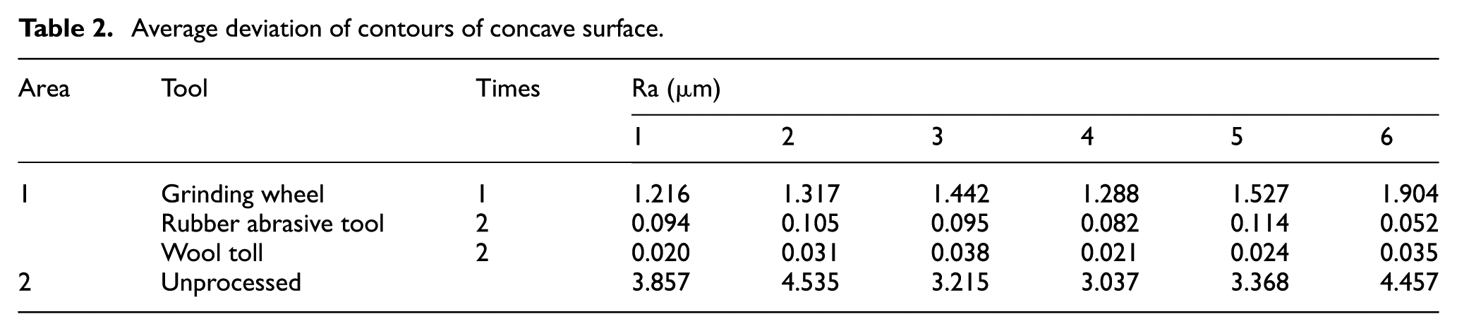
Taking six roughness measurement points in each area, the surface roughness is measured for several times. Average deviation of contours of concave surface (Ra) is calculated from the measured data (Table 2). The processed area 1 has better surface quality than the unprocessed area 2. And the surface of the workpiece is lighter than that of area 2. It shows that the polishing algorithm based on force–position control can effectively improve the quality of concave surface.
Average deviation of contours of concave surface.
Conclusion
Aiming at the problems of low production efficiency and unstable processing quality during manual polishing, this article develops a set of industrial robot automatic polishing system and puts forward a polishing method suitable for industrial robot based on force–position hybrid control. The method realizes the control of the contact force in the polishing process without modifying the hardware of the industrial robot. On the basis of the force analysis of the polishing tool, a simple gravity compensation is used to obtain the contact force between the polishing tool and the surface. The removal principle of the surface material is studied and a method for adjusting the spindle speed based on the surface normal vector is proposed. In order to realize constant force polishing along the normal vector direction, this article realizes the force–position hybrid control indirectly according to the trajectory correction along the normal vector obtained from the PI controller. Through simulation research and analysis of the control algorithm, the authors have found that the stiffness of the polishing system has a great influence on the tracking performance of the force. In view of this problem, an adaptive force–position hybrid control algorithm is proposed to make the polishing system with different polishing tools have a better force tracking performance. Finally, an experiment is performed on the concave surface with the spherical polishing tool. It is shown that adaptive force–position hybrid control algorithm based on position achieves the tracking of a given contact force. And the quality of the concave surface is significantly improved after polishing.
Footnotes
Declaration of conflicting interests
The author(s) declared no potential conflicts of interest with respect to the research, authorship and/or publication of this article.
Funding
The author(s) disclosed receipt of the following financial support for the research, authorship, and/or publication of this article: This study received financial support from the Science and Technology Support Program of Hubei Province, China (Project No. 2015BAA058).