
Abstract
Advanced manufacturing equipment heavily relies on gearboxes for optimal performance, especially in heavy-duty applications like industrial robot joints and advanced machine tools where precision and stiffness are paramount. While harmonic and cycloid gearboxes are common for their low backlash characteristic, conventional 3 K planetary gears excel in efficiency, torque density and stiffness but they are rarely utilized in high precision scenario due to backlash issue. In this study, a deformable planet carrier system (DPCS) is proposed for backlash restrain by center distance compensation. The DPCS incorporates a self-lock design, preserving low backlash feature while upholding load capacity and stiffness, meeting the demands of precision industrial equipment. To illustrate its principles, statics models demonstrate its force analysis, and FEM simulations reveal its self-lock feature. Backlash compensation model theoretically analyzes its anti-backlash effect from kinematics and geometry aspects. To validate its feasibility, the first prototype is manufactured and designated as H3K-40K-104. Experiment result prove that prototype achieves significant low backlash characteristic, with the maximum dynamic transmission error (DTE) of 20.5 arcsec and backlash of 6.561 arcsec. Stiffness hysteresis curve indicates a minimal lost motion of 20.01 arcsec. This paper provides an effective method to greatly refine precision performance in 3 K gear trains.
Introduction
Precision reduction gears serve as the cornerstone of advanced equipment, playing a pivotal role in a diverse range of applications, notably in industrial robots, machine tools, and vehicles. 1 Meticulously manufactured gears are essential for ensuring high precision and efficiency, and being indispensable components in modern machinery. Industrial robots, for instance, are highly relied on precision reduction gears for accurate and seamless movement. 2 These gears empower the robots to execute intricate tasks with exceptional precision, spanning from assembling delicate components to performing precise surgical procedures. 3 Industrial robots require diverse gearbox based on the torque and stiffness requirements of their joints, yet space constraints necessitate more compact and integrated designs. 1 High torque density enables the robots to handle substantial loads with compact structure, while broad reduction ratio range facilitates for a wide spectrum of speeds, enhancing the robot’s versatility and adaptability.4–6 Within the domain of machine tools, these performances play an equal vital role. Accurate power transmission ensures that the machine tools operate at the desired speed and torque, which is particularly critical in applications like milling, drilling, and grinding, where precision and consistency are paramount. Sufficient torque capacity enables the machine tools to tackle heavy-duty operations, while their expansive reduction ratio range offers the flexibility to adjust the speed and torque as per the requirements of the task at hand. 7
Generally, gearbox selection for robot prioritizes torque density, ratio range and torsional stiffness, which are pivotal factors influencing robot R&D. Cycloid gearboxes have complicated inner structure and various components, which makes it heavy and increases its manufacturing and maintenance cost. 8 Harmonic gearboxes have low torsional stiffness and load capacity, which limits its industrial applications. 9 3 K planetary gear is a compact mechanism that combines excellent torsional stiffness, load capacity and torque density, which is capable of meeting these requirements of advanced equipment. Current 3 K planetary gear research also employs several approaches to further enhance its performances, and exploit its potential: (i) asymmetric teeth design can boost load capacity 10 ; (ii) tooth profile modification can improve transmission efficiency 11 ; (iii) improvement in tooth contact and load distribution conditions.12,13 However, cycloid gearboxes and harmonic gearboxes are extensively utilized in modern robotic systems 9 due to their low backlash characteristic. 3 K planetary gearbox adoption in advanced robots remains limited due to challenges in achieving the necessary precision performance.
Backlash stands out as a critical factor leading to precision degradation within gear trains. From a statics perspective, lost motion serves as an indicator highly tied to backlash during repetitive movement and changes in torque direction. It represents the angular displacement where tooth come through without transmitting any force, ultimately causing accuracy loss and response hysteresis. From a dynamic perspective, backlash leads to tooth impact and vibration phenomena. This is primarily due to the velocity difference at gear mate, deteriorating contact condition and inducing pitting and spall on tooth profile. 14 It causes impact, vibration and noise during frequent bidirectional movement, ultimately impeding transmission accuracy and responsiveness. 15 Over time, gear wear and the error of initial machining and assembling contribute to irreversible increases in backlash, causing torque transmission to become nonlinear and compromising accuracy.
In order to mitigate the influence of backlash in industrial applications, some researchers focus on monitoring and predicting gear wear propagation by vibration analysis techniques, which enables to perform timely maintenance according to useful remaining lifetime estimation. 16 For example, (i) Sreepradha et al. posed artificial neural networks predict film thickness and lubrication to assess wear conditions, 17 (ii) Feng et al. introduced digital twin technologies establish real-time synchronization between physical and virtual models, enabling continuous assessment of surface degradation and gear wear. 18 Accurate lifetime prediction and timely gearbox replacement are effective strategies for maintaining optimal performance in industrial equipment. Intelligent and real-time gear assessment also benefits engineers to judge the wear progression in gear system. However, other researchers tend to focus on proposing mechanical and algorithmic solutions to address backlash issues directly: (i) backlash compensation algorithm in control system from Nordin and Gutman 19 ; (ii) traction drive mechanisms proposed by Oba and Fujimoto20,21; (iii) flexible anti-backlash mechanisms on strain wave gear reducer invented by Ling et al. 22 Although current studies offer various thinking to realize low backlash characteristic, many structures rely on complicated components, advanced machining techniques and expensive control systems, which make them impractical and unreliable. In relevant research, flexible anti-backlash mechanism normally shows higher precision improvement, but it also compromises torsional stiffness.23–25 Apparently, a substantial decrease in the overall performance of the gearbox undermines the industrial significance of the anti-backlash mechanism. Low stiffness characteristic enlarges the precision loss under heavy-duty work condition due to it induces larger deformation on gear trains, despite the backlash is well restrained. It impedes the anti-backlash gearbox from widely applied in industrial equipment.
To fill the research gap, this study aims to introduce a deformable planet carrier, which equips a self-lock taper sleeve, forming an innovative deformable anti-backlash system. Deformable planet carrier realizes center distance adjustment to compensate backlash, and self-lock design avoids the carrier shrinkage under load condition. Our prototype adopts Wolfrom -based design (Figure 1), first proposed by Ulrich Wolfrom in Germany in 1912, 26 which is used to validate DPCS’s feasibility. In experiment, this prototype, designated as H3K Gear, reveals outstanding precision performance, and represents a clear low-backlash characteristic without compromising torsional stiffness and load capacity. The lost motion and dynamic transmission error can be maintained within 25 arcsec.

Wolfrom-based 3 K planetary gear design.
In section 2, a basic H3K Gear framework is given. Section 3 introduces the principle of DPCS, its statics models and backlash compensation model. The effect of self-lock taper sleeve and center distance change then is revealed by Finite Element Method (FEM). In section 4 & section 5, prototype experiments are conducted to further prove the feasibility of DPCS. In the end, section 6 provides a detailed discussion and conclusion about this study.
Basic H3K Gear structure framework
Figure 1 illustrates the layout comprising two stages: a primary planetary gear train and an additional planet- & output-ring gear stage. Within the transmission trains, sun- and output-ring gear function as the input and output shaft respectively. The planet gears situated at the deformable planet carrier, engage with both the fixed-ring gear and output-ring gear simultaneously, while orbiting around the sun gear. The tooth profile adopts an involute shape with a helical angle, enhancing the contact ratio and ensuring seamless transmission. Equations (1)–(3) give a typical reduction ratio relationship in 3 K planetary gearbox. In this study, our anti-backlash mechanism is equipped at the second stage. Variables required in derivation process are defined in Table 1.

Variable naming list.

H3K Gear can be transferred to a fixed-axis gear train, and its transmission ratio is defined by equation (1), where the rotational speed of fix ring gear

For each reduction stage, total ratio
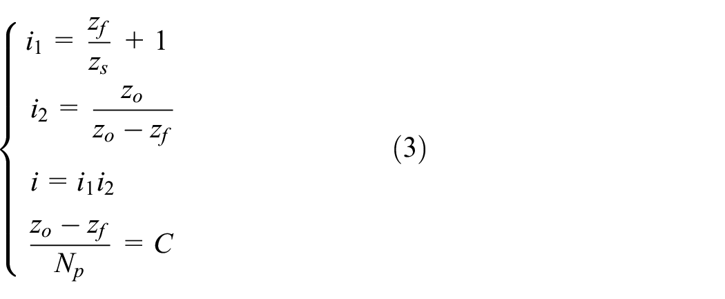
where
Anti-backlash design
DPCS principles
The Deformable Planet Carrier System (DPCS) is the key component within the H3K Gear, facilitating the pursuit of higher transmission precision and reduced lost motion. Figure 2(a)) illustrates the innovative system comprises a self-lock taper sleeve, planet gears, spring washer, and a deformable carrier, effectively replacing the conventional rigid carrier to restrain backlash. As shown in Figure 2(b)), deformable carrier utilizes springs to connect planet gears, facilitating the adjustment of their radial positions by varying the pitch circle circumference of the three planet shafts. Backlash existing between planet- and ring gears is refilled in this process.

The conceptual diagram of (a) DPCS structure; (b) its anti-backlash process.
Maintain the anti-backlash state under heavy load is the kernel of this mechanism. Generally, designed spring stiffness is unable to prevent carrier shrinkage under heavy torque, compensated backlash then reappears along with the spring shrinkage under load. To address this issue, taper sleeve is designed with sufficient stiffness to support carrier. Spring washers are uniformly positioned along the carrier’s bottom using screws to push the taper sleeve inward through preload. In the presence of friction at the contact surface, cone angle generates a self-lock effect that prevents the taper sleeve from disengaging under load. Despite the spring stiffness is weak, the taper sleeve effectively impedes large carrier shrinkage. It thereby prevents the resurgence of refilled center distance and compensated backlash. The H3K planetary gearbox is equipped with DPCS, thus endowing it with anti-backlash properties.
In the backlash refilling process, the planet gears must experience parallel displacement along the radial direction without exhibiting tilt behavior. To achieve this target, stringent constraints are placed on machining errors occurring on the contact surface between taper sleeve and deformable carrier. A matching procedure is wielded between taper sleeve and deformable carrier based on measured machining error. This step is crucial to prevent uneven deformation of carrier after taper sleeve insertion, which could lead to planet tilting and the irregular engagement, resulting in increased contact stress, vibration and potential gear failure. Additionally, by implementing tooth profile modifications and axial adjustments, the contact conditions between the planet gear and internal ring gears can be improved. Compared with the traditional rigid carrier design, this deformable carrier design maintains the same level of support effect for the planet gear without induce extra distortion, tilting and shifting, preserving tooth load capacity. In terms of spring types, the conceptual diagram employs a straightforward Z-shaped design to illustrate its operational principle.
DPCS statics model
Figure 3 illustrates the force analysis diagrams of DPCS at steady state. Planet gears are evenly distributed along the carrier and separated by springs. Assume the engagement point locates at pitch circle, the friction coefficient on tooth surface as
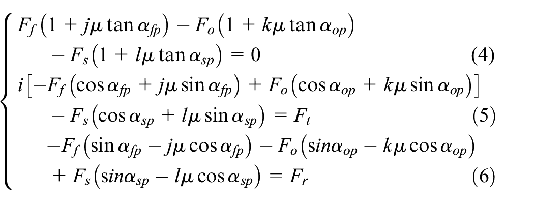

Force analysis diagrams: (a) entire force analysis under load; (b) taper sleeve self-lock force analysis; (c) one-third carrier force analysis.
Where
Self-lock taper sleeve maintains carrier position after backlash compensation, as Figure 3(b)). When finish installation, spring washer imposes

From the theoretical basis above, DPCS has two different mechanic models in anti-backlash process and loading process, respectively.
Anti-backlash process
Anti-backlash process is carried out under no-load condition, self-lock taper sleeve squeezes carrier and extends its springs after installation. The force equilibrium equations (10) and (11) of one-third carrier can be derived from Figure 3(c)). Note that

Consider

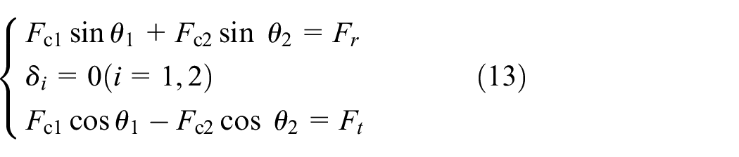
Figure 4 describes the process of backlash generation and compensation. Circumferential backlash on each side of tooth profile is symbolized as

Ideal process of tooth movement and backlash complement: (a) Initial non-backlash status under bilateral meshing, (b) Tooth profile degradation generates backlash when working, and (c) Carrier modification adaptively compensates the backlash and forms new bilateral meshing status.
Consider equation (7), the critical anti-backlash point is found when
Loading process
DPCS reveals its self-lock characteristic under loading condition. On the contact surface between taper sleeve and carrier, equation (14) is derived according to Figure 3(b)).

Therefore, taper sleeve keeps self-lock status to prevent carrier shrinkage under loading condition, radial force
FEM result of self-lock taper sleeve
FEM simulations serve to validate the feasibility of DPCS theoretically based on prototype H3K-40K-104, and a FEM model of gear system is established, comprising the DPCS, sun-, fixed ring- and output ring gear. Table 2 gives its detailed design parameters.
Major design parameters of H3K-40K-104 prototype.

The initial center distance between the planet gears and ring gears is intentionally set slightly smaller than the ideal non-backlash status to account for a certain tooth backlash. The simulation commences from establishing the initial status, defining essential boundary conditions, regulating element interference, and setting contact parameters.
Subsequently, a 1 kN external force is applied to push the taper sleeve inward, which is facilitated by spring washers. In the final step, a rated torque of 400 Nm is applied to the output ring gear, with the input shaft fixed as boundary conditions. Two different friction coefficients are considered: 0.15 and 0.01. These values determines whether the taper sleeve attains self-lock or non-self-lock status, respectively. Then, the post-processing results of displacement along axial and radial direction are listed in Table 3.
The FEM displacement result of DPCS after taper sleeve insertion.

Figure 5 illustrates the process of taper sleeve insertion under external force, showcasing a 1.254 mm axial movement of the taper sleeve. In the self-lock status, the taper sleeve maintains its position at 1.2496 mm under load. By comparison, a distinct taper sleeve extrusion behavior occurs in the non-self-lock status when subjected to a load, and the taper sleeve moves 1.0309 mm toward outside. In Figure 6, the evolution of shaft pitch diameters under different statuses is depicted. Taper sleeve insertion extends the carrier spring, and planet shaft move radially with approximate 0.117 mm. The self-lock status exhibits significant radial stiffness, with the shaft effectively maintaining this movement at 0.096 mm under a 400 Nm torque. This shaft displacement effectively preserves the central distance between the planet gear and the two ring gears, showcasing an anti-backlash characteristic. However, the non-self-lock status fails to prevent carrier shrinkage, leading to a 0.118 mm inward movement of the shaft. Figure 7 demonstrates tooth engagement status, both sliding and sticking status represent contact establishment. Before taper sleeve insertion, half of tooth has contacted bilaterally, and the other half of tooth exist backlash. Then, carrier extension increases tooth contact area, and slight preload enables to well restrain backlash.

Axial displacement contour of taper sleeve in H3K-40K-104 FEM model /unit: mm: (a) taper sleeve has been inserted (1.254 mm); (b) self-lock status under 400 Nm load (1.2496 mm); (c) non-self-lock status under 400 Nm load (0.0091 mm).

Radial displacement contour of planet shaft in H3K-40K-104 FEM model /unit: mm: (a) taper sleeve has been inserted (0.117 mm); (b) self-lock status under 400 Nm load (0.096 mm); (c) non-self-lock status under 400 Nm load (-0.118 mm).

Contact status contour of output ring gear in H3K-40K-104 FEM model: (a) before taper sleeve insertion; (b) after taper sleeve insertion.
Backlash compensation model
Backlash typically arises at each gear pair owing to manufacturing and assembly variations, but the impacts on output accuracy is varying based on their positions within the gear trains. The backlash between the planet gears and ring gears directly affects the output precision of gear trains, whereas that between sun gear and planet gears necessitates consideration of the gear ratio for its influence to be transmitted to the output end. Major variables and definitions used in this section are listed below as Table 4.
Major variables and definitions list.

For planet- and sun gear pair, the deviation in center distance is denoted as


Consider the involute function, and the difference between

Therefore, the simplified center distance deviation equation between sun- and planet gear, is noted as

Convert the circumferential backlash to angular backlash at sun gear, output ring gear and fix ring gear respectively.

Each angular backlash compared with planet gear


After backlash compensation, center distance deviation on each gear pair is affected by
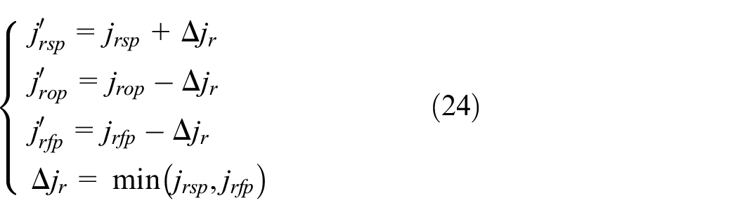
As a result, angular backlash induced by

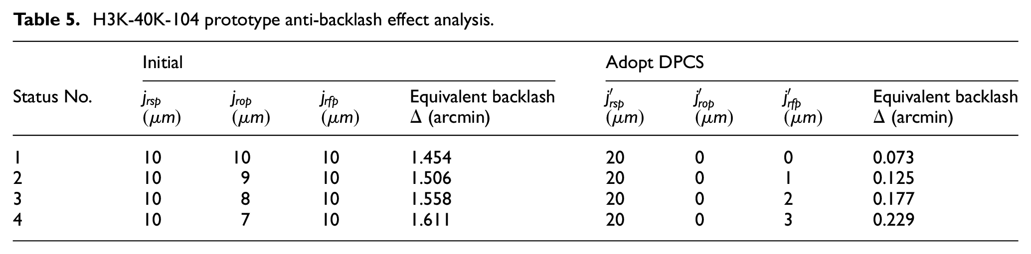
In practice, this backlash compensation model is utilized to analyze the backlash of prototype H3K-40K-104. In the gear manufacturing, precise center distance control is crucial to gearbox assembly. A center distance ranges from
Assume an ideal condition is designated as
Additionally, the difference on center distance deviation between two ring gears also induces extra equivalent backlash. Assume a situation that the difference between
H3K-40K-104 prototype anti-backlash effect analysis.
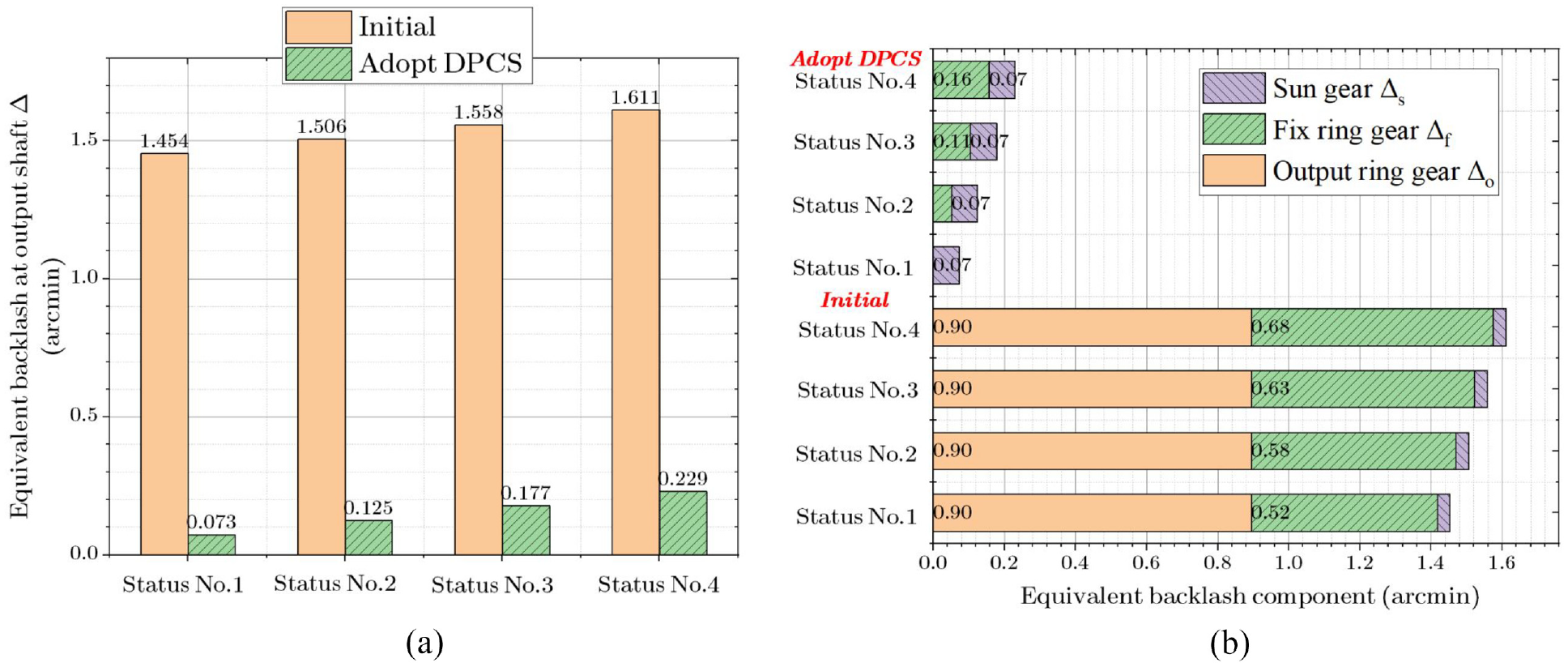
H3K-40K-104 prototype equivalent backlash comparison, (a) Overall equivalent backlash under Status No.1 – No.4 at output shaft; (b) The equivalent backlash of sun gear, fix ring gear and output ring gear under Status No.1 – No.4 at output shaft.
Prototype experiment test
Sample preparation
In order to further prove the feasibilities of DPCS and validate its potential, we developed and produced the first H3K Gear prototype with rated torque 400 Nm and reduction ratio 104, which is encoded as H3K-40K-104. This prototype adopts Wolfrom-based structure, and equips DPCS to restrain backlash on ring gears. Main bearing uses integrated design to make structure compact. No ball bearing is used on sun gear side in this test section.
Three H3K Gear samples (Figure 9) are used in experiments, which share the same lubrication condition. Sample numbers are noted as

H3K-40K-104 prototype aspects, (a) side; (b) back; (c) section.
H3K-40K-104 sample backlash table.

Test equipment and test environment
In this section, the feasibility of H3K Gear and its design will be shown, and comprehensive performance and capacities can be further proved.
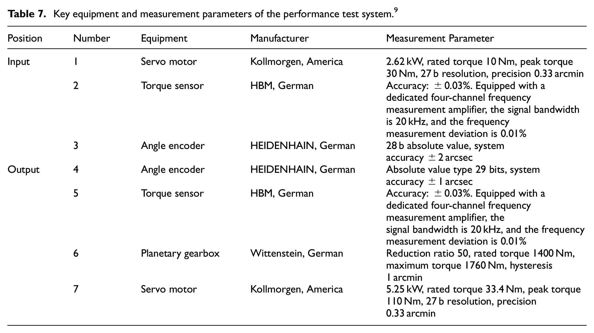
The performance test system is presented in Figure 10, the tested H3K Gear is installed between two pairs of high-precision angle encoder and torque sensor, which measures real-time angular displacement and torque respectively at both input and output end of H3K Gear. In this experiment test, torsional stiffness, hysteresis characteristic and transmission accuracy can be obtained. Angle encoders are installed closed to tested gearbox in case of displacement measure error caused by torque sensor deformation. An extra precision planetary gearbox installed at output side it to enlarge load torque according to experiment requirement. The test environment for precision is at a room temperature of

Performance test system. 9
Key equipment and measurement parameters of the performance test system. 9
Test result
Dynamic transmission error measurement
Dynamic transmission error (


Transmission error curves of three H3K-40K-104 samples #1, #2 and #3respectively, (a) clockwise; (b) anticlockwise.
(Figure 11) It is can be seen that H3K-40K-104 prototypes reach low DTE within 25 arcsec and that of traditional planetary gearbox usually ranges from 2 to 4 arcmin. 8 DPCS makes DTE dramatically decrease about 80% compared with traditional design, because anti-backlash condition restrains tooth vibration during engagement period, which ensures smooth torque transmission.
Positioning error measurement
Positioning error (

Positioning error curves of three H3K-40K-104 samples #1, #2, and #3 respectively.
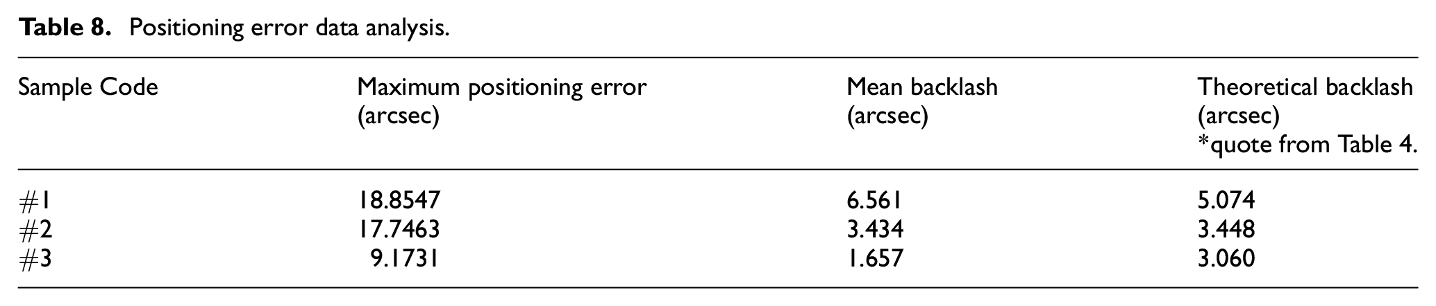
Table 8. reveals the backlash of H3K samples is within 6.561 arcsec, which closes to theoretical values, and the maximum positioning error can be controlled within 20 arcsec. When considering the measuring error of HEIDENHAIN angle encoders integrated into the performance test system, it is noted that the errors are ±2 arcsec at input end and ±1 arcsec at output end. The measured mean backlash and theoretical backlash conducted by previous model appear strong trend correlation, and their deviation remains within the bounds of the measuring error. Additionally, the installation error of the gearbox, measurement error on tooth parameters are other possible factors that could contribute to the discrepancies.
Positioning error data analysis.
Stiffness hysteresis test
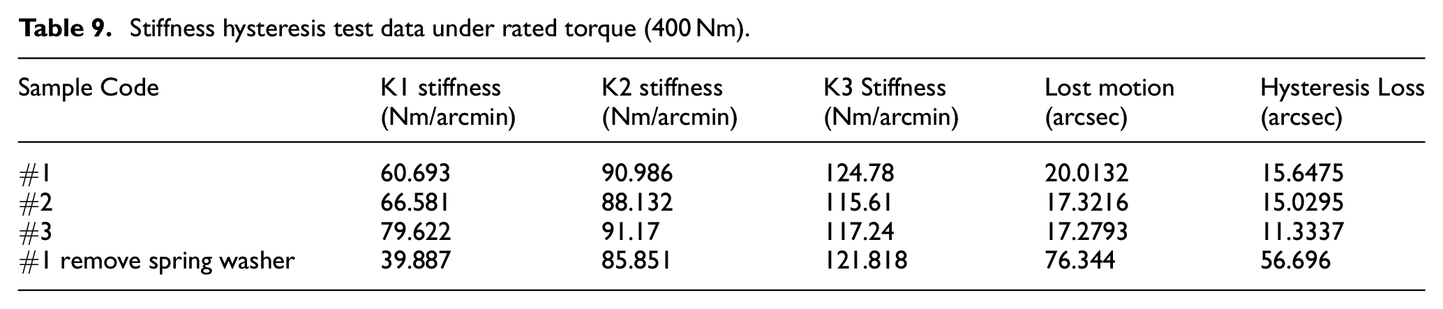
The stiffness hysteresis characteristic serves as a valuable tool for presenting the static performance of reduction gears in industrial applications. To analyze this characteristic, the input shaft of the tested gearbox is fixed, and a clockwise load torque is gradually applied to the output shaft until reaching the rated torque of 400 Nm. Subsequently, the torque is gradually unloaded to zero and reloaded in the opposite direction to −400 Nm (with the negative symbol denoting the anticlockwise direction). After unloading to zero again, it is reloaded following the same process as the initial loading until the load torque reaches 400 Nm. An encoder installed at the output end records the entire angular displacement, enabling the plotting of a stiffness hysteresis curve. In data analysis process, mean angular displacement between output torque at ± 3% rated torque on curve is defined as the geometric lost motion of tested sample. In addition, angular displacement difference when torque load reach zero is defined as hysteresis loss. The two parameters are affected by many factors, such as backlash, oil film resistance and internal friction, that can be treated as static precision performance of gearbox. The comprehensive torsion stiffness is defined as the ratio of the total torque load to the bandwidth of displacement during the load cycle.
The experiment result (Figure 13) demonstrates that H3K Gear has low-backlash characteristic, as evidenced the curve behavior under low torque loads. The gradient of the curve represents the torsional stiffness at each measure point. Owing to its anti-backlash properties, H3K Gear exhibits a commendable stiffness consistency across various torque conditions. Define K1, K2 and K3 stiffness by the mean value of segmental stiffness on bilateral direction at range 0%–15%, 15%-50% and 50%-100% rated torque respectively.

Stiffness Hysteresis curves of three H3K-40K-104 samples #1, #2, and #3 respectively.
To reflect the low backlash characteristic in stiffness curve, reinstall the DPCS in sample H3K-40K-104
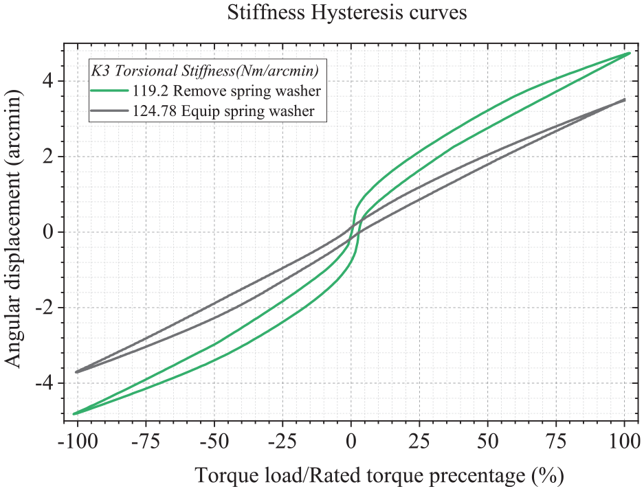
Stiffness hysteresis curves of H3K-40K-104 #1 based on spring washer status.
Stiffness hysteresis test data under rated torque (400 Nm).
Discussion
In this study, a novel 3 K planetary gearbox anti-backlash mechanism DPCS is proposed. Compared with traditional structure, deformable planetary carrier system enables to adjust gear center distance to effectively compensate backlash caused by wearing, machining error and assembly error. Taper sleeve design, based on self-lock principle, is to prevent carrier shrinkage caused by torque load, maintaining great precision retaining ability under load.
Static model and backlash compensation model give a holistic perspective about structural feasibility and anti-backlash efficacy. Backlash present in the ring gear significantly impacts output precision, whereas that influence in sun gear is minimal and can be neglected due to geometric and kinematic relationships within 3 K gear trains. Center distance compensation decreases 20–30 times comprehensive output backlash, and dramatically increases precision. Finite element method reveals the self-lock characteristic of carrier, which enables to well restrain backlash under load condition.
Prototype experiment results demonstrate a distinct reduction in backlash characteristics, with the dynamic transmission of H3K-40K-104 measuring less than 20.5 arcsec. Additionally, lost motion and mean backlash also perform 20.0132 arcsec and 6.561 arcsec respectively, aligning closely with theoretical value. These finding prove the structure advantages and model feasibility. Therefore, DPCS emerges as an effective method to tackle the precision issue within the 3 K planetary structure, presenting a new R&D direction for the next generation of gearbox. By implementing the Deformable Planet Carrier System, the H3K Gear system showcases a forward-looking approach to addressing precision-related challenges in gear mechanisms. This innovative design not only enhances transmission accuracy and minimizes lost motion but also demonstrates a strategic balance between performance optimization and load-bearing capacity.
To fully leverage the capabilities of H3K Gear, there are some plans of further studies and experiments. Areas that could benefit from further exploration include carrier vibration, backdrivability, impact response, precision over the product’s lifetime, load distribution, and noise characteristics. Moreover, investigating the precise correlations among spring parameters, the anti-backlash effect, and the overall gearbox performance stands out as a crucial research avenue for H3K Gear. This research direction aims to delve into a more comprehensive set of advantages on design stage and maximize the potential of the 3 K gear system.
Patents
[1] LING, Zilong. DISPLACEMENT PLANETARY CARRIER SYSTEM AND PLANETARY TRANSMISSION DEVICE THEREOF[P]. Tianjin City CN113757349A, 2021-12-07. (In Chinese)
[2] LING, Zilong. DISPLACEMENT PLANETARY CARRIER SYSTEM AND PLANETARY TRANSMISSION DEVICE THEREOF[P]. WO2023065072,2023-04-27.
Footnotes
Handling Editor: Aarthy Esakkiappan
Author Contributions
Conceptualization, Z.L.; methodology, Z.L.; software, L.Z. and Y.Z.; validation, D.X. and Y.L.; formal analysis, L.Z. and Y.Z.; investigation, L.Z., D.X. and Y.L.; resources, X.X. and Z.L.; writing—original draft preparation, Y.Z.; writing—review and editing, D.X. and L.Z.; visualization, Z.J., S.X. and Y.Z.; supervision, Z.L. and D.X.; project administration, Z.L. and Y.L.; funding acquisition, Z.L.; All authors have read and agreed to the published version of the manuscript.
Declaration of conflicting interests
The author(s) declared no potential conflicts of interest with respect to the research, authorship, and/or publication of this article.
Funding
The author(s) received no financial support for the research, authorship, and/or publication of this article.
Data Availability Statement
The data that support the findings of this study are available from the corresponding author upon reasonable request.